disc YAMAHA YZF-R125 2015 Owners Manual
[x] Cancel search | Manufacturer: YAMAHA, Model Year: 2015, Model line: YZF-R125, Model: YAMAHA YZF-R125 2015Pages: 98, PDF Size: 6.92 MB
Page 3 of 98
INTRODUCTION
EAU10103
Welcome to the Yamaha world of motorcycling!
As the owner of the YZF-R125/YZF-R125A, you are benefiting from Yamaha’s vast experience and newest technology re-
garding the design and manufacture of high-quality products, which have earned Yamaha a reputation for dependability.
Please take the time to read this manual thoroughly, so as to enjoy all advantages of your YZF-R125/YZF-R125A. The Own-
er’s Manual does not only instruct you in how to operate, inspect and maintain your motorcycle, but also in how to safe-
guard yourself and others from trouble and injury.
In addition, the many tips given in this manual will help keep your motorcycle in the best possible condition. If you have any
further questions, do not hesitate to contact your Yamaha dealer.
The Yamaha team wishes you many safe and pleasant rides. So, remember to put safety first!
Yamaha continually seeks advancements in product design and quality. Therefore, while this manual contains the most cur-
rent product information available at the time of printing, there may be minor discrepancies between your motorcycle and
this manual. If there is any question concerning this manual, please consult a Yamaha dealer.
WARNING
EWA10032
Please read this manual carefully and completely before operating this motorcycle.
U5D7E5E0.book Page 1 Thursday, August 21, 2014 9:30 AM
Page 43 of 98
PERIODIC MAINTENANCE AND ADJUSTMENT
6-1
6
EAU17245
Periodic inspection, adjustment, and
lubrication will keep your vehicle in the
safest and most efficient condition
possible. Safety is an obligation of the
vehicle owner/operator. The most im-
portant points of vehicle inspection,
adjustment, and lubrication are ex-
plained on the following pages.
The intervals given in the periodic
maintenance charts should be simply
considered as a general guide under
normal riding conditions. However, de-
pending on the weather, terrain, geo-
graphical location, and individual use,
the maintenance intervals may need to
be shortened.
WARNING
EWA10322
Failure to properly maintain the vehi-
cle or performing maintenance ac-
tivities incorrectly may increase
your risk of injury or death during
service or while using the vehicle. If
you are not familiar with vehicle ser-
vice, have a Yamaha dealer perform
service.
WARNING
EWA15123
Turn off the engine when performing
maintenance unless otherwise
specified.
A running engine has moving
parts that can catch on body
parts or clothing and electrical
parts that can cause shocks or
fires.
Running the engine while ser-
vicing can lead to eye injury,
burns, fire, or carbon monoxide
poisoning – possibly leading to
death. See page 1-3 for more in-
formation about carbon monox-
ide.
WARNING
EWA15461
Brake discs, calipers, drums, and
linings can become very hot during
use. To avoid possible burns, let
brake components cool before
touching them.
EAU17303
Emission controls not only function to
ensure cleaner air, but are also vital to
proper engine operation and maximum
performance. In the following periodic
maintenance charts, the services relat-
ed to emissions control are grouped
separately. These services require
specialized data, knowledge, and
equipment. Maintenance, replace-
ment, or repair of the emission control
devices and systems may be per-
formed by any repair establishment or
individual that is certified (if applicable).
Yamaha dealers are trained and
equipped to perform these particular
services.
U5D7E5E0.book Page 1 Thursday, August 21, 2014 9:30 AM
Page 50 of 98
PERIODIC MAINTENANCE AND ADJUSTMENT
6-8
6
EAU18732
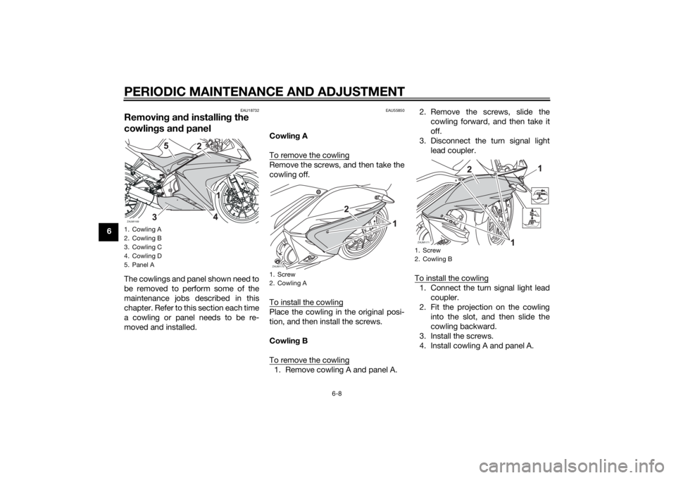
Removing and installing the
cowlings and panelThe cowlings and panel shown need to
be removed to perform some of the
maintenance jobs described in this
chapter. Refer to this section each time
a cowling or panel needs to be re-
moved and installed.
EAU55850
Cowling A
To remove the cowlingRemove the screws, and then take the
cowling off.
To install the cowlingPlace the cowling in the original posi-
tion, and then install the screws.
Cowling B
To remove the cowling1. Remove cowling A and panel A.2. Remove the screws, slide the
cowling forward, and then take it
off.
3. Disconnect the turn signal light
lead coupler.
To install the cowling
1. Connect the turn signal light lead
coupler.
2. Fit the projection on the cowling
into the slot, and then slide the
cowling backward.
3. Install the screws.
4. Install cowling A and panel A.
1. Cowling A
2. Cowling B
3. Cowling C
4. Cowling D
5. Panel AZAUM1169
1. Screw
2. Cowling AZAUM1170
1. Screw
2. Cowling BZAUM1171
U5D7E5E0.book Page 8 Thursday, August 21, 2014 9:30 AM
Page 73 of 98
PERIODIC MAINTENANCE AND ADJUSTMENT
6-31
6
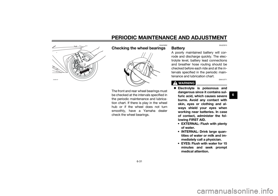
EAU23292
Checking the wheel bearingsThe front and rear wheel bearings must
be checked at the intervals specified in
the periodic maintenance and lubrica-
tion chart. If there is play in the wheel
hub or if the wheel does not turn
smoothly, have a Yamaha dealer
check the wheel bearings.
EAU23315
BatteryA poorly maintained battery will cor-
rode and discharge quickly. The elec-
trolyte level, battery lead connections
and breather hose routing should be
checked before each ride and at the in-
tervals specified in the periodic main-
tenance and lubrication chart.
WARNING
EWA10771
Electrolyte is poisonous and
dangerous since it contains sul-
furic acid, which causes severe
burns. Avoid any contact with
skin, eyes or clothing and al-
ways shield your eyes when
working near batteries. In case
of contact, administer the fol-
lowing FIRST AID.
EXTERNAL: Flush with plenty
of water.
INTERNAL: Drink large quan-
tities of water or milk and im-
mediately call a physician.
EYES: Flush with water for 15
minutes and seek prompt
medical attention.
ZAUM1187
U5D7E5E0.book Page 31 Thursday, August 21, 2014 9:30 AM
Page 74 of 98
PERIODIC MAINTENANCE AND ADJUSTMENT
6-32
6Batteries produce explosive hy-
drogen gas. Therefore, keep
sparks, flames, cigarettes, etc.,
away from the battery and pro-
vide sufficient ventilation when
charging it in an enclosed
space.
Take care not to spill electrolyte
on the drive chain, as this may
weaken it, shorten chain life and
possibly result in an accident.
KEEP THIS AND ALL BATTER-
IES OUT OF THE REACH OF
CHILDREN.
To check the electrolyte level
1. Place the vehicle on a level sur-
face and hold it in an upright posi-
tion.TIPMake sure that the vehicle is posi-
tioned straight up when checking the
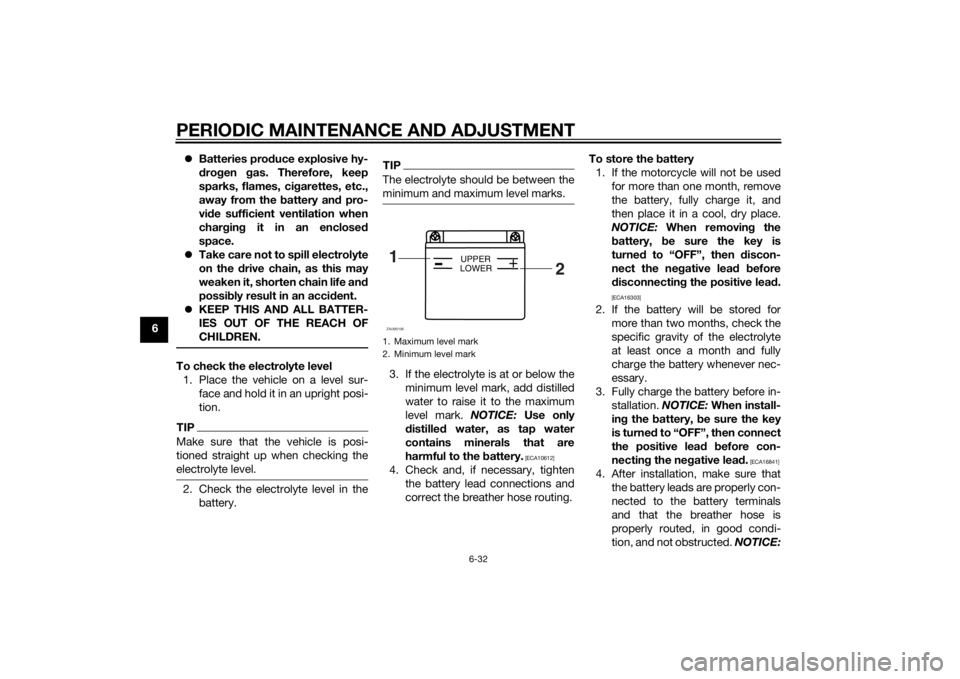
electrolyte level.2. Check the electrolyte level in the
battery.
TIPThe electrolyte should be between the
minimum and maximum level marks.3. If the electrolyte is at or below the
minimum level mark, add distilled
water to raise it to the maximum
level mark. NOTICE: Use only
distilled water, as tap water
contains minerals that are
harmful to the battery.
[ECA10612]
4. Check and, if necessary, tighten
the battery lead connections and
correct the breather hose routing.To store the battery
1. If the motorcycle will not be used
for more than one month, remove
the battery, fully charge it, and
then place it in a cool, dry place.
NOTICE: When removing the
battery, be sure the key is
turned to “OFF”, then discon-
nect the negative lead before
disconnecting the positive lead.
[ECA16303]
2. If the battery will be stored for
more than two months, check the
specific gravity of the electrolyte
at least once a month and fully
charge the battery whenever nec-
essary.
3. Fully charge the battery before in-
stallation. NOTICE: When install-
ing the battery, be sure the key
is turned to “OFF”, then connect
the positive lead before con-
necting the negative lead.
[ECA16841]
4. After installation, make sure that
the battery leads are properly con-
nected to the battery terminals
and that the breather hose is
properly routed, in good condi-
tion, and not obstructed. NOTICE:
1. Maximum level mark
2. Minimum level mark1
2
+
UPPER
LOWER
ZAUM0106
U5D7E5E0.book Page 32 Thursday, August 21, 2014 9:30 AM
Page 80 of 98
PERIODIC MAINTENANCE AND ADJUSTMENT
6-38
63. Remove the brake caliper by re-
moving the bolts. NOTICE: Do
not apply the brake after the
wheel and brake disc have been
removed, otherwise the brake
pads will be forced shut.
[ECA11073]
4. Pull the wheel axle out, and then
remove the wheel.
To install the front wheel
1. Lift the wheel up between the fork
legs.
2. Insert the wheel axle.
3. Lower the front wheel so that it is
on the ground.
4. Install the brake caliper by install-
ing the bolts.TIPMake sure that there is enough space
between the brake pads before install-
ing the brake caliper onto the brake
disc.5. Tighten the wheel axle to the
specified torque.
6. Tighten the wheel axle pinch bolt
A and pinch bolt B to the specified
torques.7. Retighten the wheel axle pinch
bolt A to the specified torque.
8. Tighten the brake caliper bolts to
the specified torques.
9. Push down hard on the handlebar
several times to check for proper
fork operation.
EAU44802
Rear wheel (for non-ABS
models)
WARNING
EWA14841
For the ABS model, have a Yamaha
dealer remove and install the wheel.
EAU56701
To remove the rear wheel
WARNING
EWA10822
To avoid injury, securely support the
vehicle so there is no danger of it
falling over.1. Loosen the axle nut.
Tightening torques:
Wheel axle:
59 Nm (5.9 m·kgf, 43 ft·lbf)
Front wheel axle pinch bolt:
23 Nm (2.3 m·kgf, 17 ft·lbf)
Brake caliper bolt:
38 Nm (3.8 m·kgf, 27 ft·lbf)
U5D7E5E0.book Page 38 Thursday, August 21, 2014 9:30 AM
Page 81 of 98
PERIODIC MAINTENANCE AND ADJUSTMENT
6-39
6
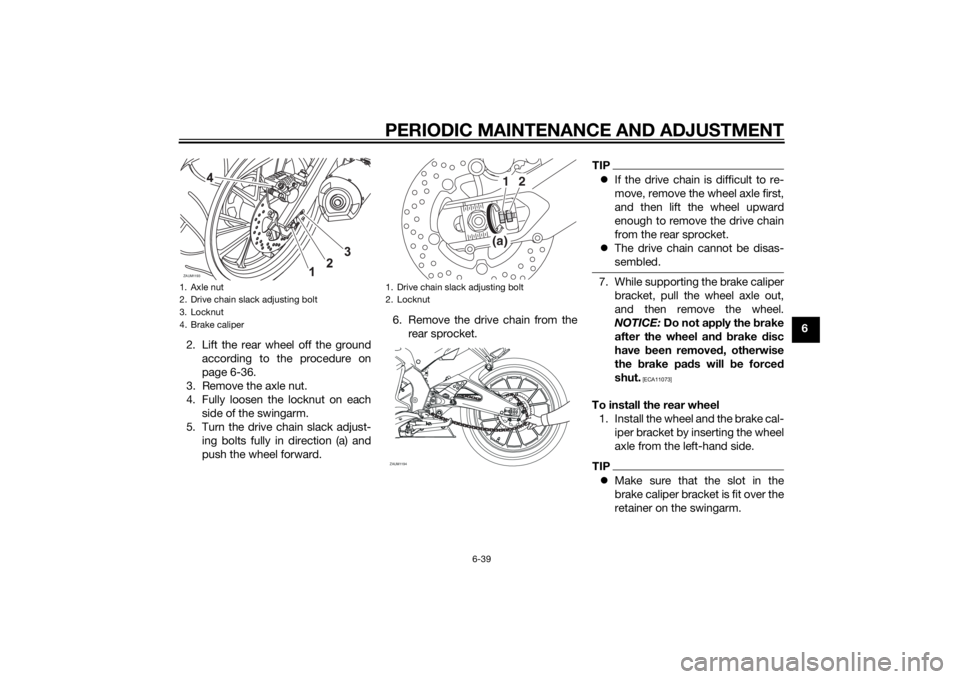
2. Lift the rear wheel off the ground
according to the procedure on
page 6-36.
3. Remove the axle nut.
4. Fully loosen the locknut on each
side of the swingarm.
5. Turn the drive chain slack adjust-
ing bolts fully in direction (a) and
push the wheel forward.6. Remove the drive chain from the
rear sprocket.
TIPIf the drive chain is difficult to re-
move, remove the wheel axle first,
and then lift the wheel upward
enough to remove the drive chain
from the rear sprocket.
The drive chain cannot be disas-
sembled.7. While supporting the brake caliper
bracket, pull the wheel axle out,
and then remove the wheel.
NOTICE: Do not apply the brake
after the wheel and brake disc
have been removed, otherwise
the brake pads will be forced
shut.
[ECA11073]
To install the rear wheel
1. Install the wheel and the brake cal-
iper bracket by inserting the wheel
axle from the left-hand side.TIPMake sure that the slot in the
brake caliper bracket is fit over the
retainer on the swingarm.
1. Axle nut
2. Drive chain slack adjusting bolt
3. Locknut
4. Brake caliperZAUM1193
1. Drive chain slack adjusting bolt
2. Locknut
(a)1
2
ZAUM1194
U5D7E5E0.book Page 39 Thursday, August 21, 2014 9:30 AM
Page 87 of 98
MOTORCYCLE CARE AND STORAGE7-2
7 off any detergent residue using
plenty of water, as it is harmful
to plastic parts.
Do not use any harsh chemical
products on plastic parts. Be
sure to avoid using cloths or
sponges which have been in
contact with strong or abrasive
cleaning products, solvent or
thinner, fuel (gasoline), rust re-
movers or inhibitors, brake fluid,
antifreeze or electrolyte.
Do not use high-pressure wash-
ers or steam-jet cleaners since
they cause water seepage and
deterioration in the following ar-
eas: seals (of wheel and swing-
arm bearings, fork and brakes),
electric components (couplers,
connectors, instruments,
switches and lights), breather
hoses and vents.
For motorcycles equipped with
a windshield: Do not use strong
cleaners or hard sponges as
they will cause dulling
or
scratching. Some cleaning
compounds for plastic may
leave scratches on the wind-shield. Test the product on a
small hidden part of the wind-
shield to make sure that it does
not leave any marks. If the wind-
shield is scratched, use a quality
plastic polishing compound af-
ter washing.
After normal useRemove dirt with warm water, a mild
detergent, and a soft, clean sponge,
and then rinse thoroughly with clean
water. Use a toothbrush or bottlebrush
for hard-to-reach areas. Stubborn dirt
and insects will come off more easily if
the area is covered with a wet cloth for
a few minutes before cleaning. Use the
special sponge, which is located under
the tool kit, to clean the muffler and to
remove any discoloration from it.
After riding in the rain, near the sea oron salt-sprayed roadsSince sea salt or salt sprayed on roads
during winter are extremely corrosive
in combination with water, carry out
the following steps after each ride in
the rain, near the sea or on salt-
sprayed roads.
TIPSalt sprayed on roads in the winter
may remain well into spring.1. Clean the motorcycle with cold
water and a mild detergent, after
the engine has cooled down.
NOTICE: Do not use warm wa-
ter since it increases the corro-
sive action of the salt.
[ECA10792]
2. After drying the motorcycle, apply
a corrosion protection spray on all
metal, including chrome- and
nickel-plated, surfaces to prevent
corrosion.
After cleaning
1. Dry the motorcycle with a chamois
or an absorbing cloth.
2. Immediately dry the drive chain
and lubricate it to prevent it from
rusting.
3. Use a chrome polish to shine
chrome, aluminum and stainless-
steel parts, including the exhaust
system. (Even the thermally in-
duced discoloring of stainless-
steel exhaust systems can be re-
moved through polishing.)
U5D7E5E0.book Page 2 Thursday, August 21, 2014 9:30 AM
Page 88 of 98
MOTORCYCLE CARE AND STORAGE
7-3
74. To prevent corrosion, it is recom-
mended to apply a corrosion pro-
tection spray on all metal,
including chrome- and nickel-plat-
ed, surfaces.
5. Use spray oil as a universal clean-
er to remove any remaining dirt.
6. Touch up minor paint damage
caused by stones, etc.
7. Wax all painted surfaces.
8. Let the motorcycle dry completely
before storing or covering it.
WARNING
EWA11132
Contaminants on the brakes or tires
can cause loss of control.
Make sure that there is no oil or
wax on the brakes or tires.
If necessary, clean the brake
discs and brake linings with a
regular brake disc cleaner or
acetone, and wash the tires with
warm water and a mild deter-
gent. Before riding at higher
speeds, test the motorcycle’s
braking performance and cor-
nering behavior.
NOTICE
ECA10801
Apply spray oil and wax spar-
ingly and make sure to wipe off
any excess.
Never apply oil or wax to any
rubber and plastic parts, but
treat them with a suitable care
product.
Avoid using abrasive polishing
compounds as they will wear
away the paint.TIPConsult a Yamaha dealer for ad-
vice on what products to use.
Washing, rainy weather or humid
climates can cause the headlight
lens to fog. Turning the headlight
on for a short period of time will
help remove the moisture from the
lens.
EAU43204
StorageShort-term
Always store your motorcycle in a cool,
dry place and, if necessary, protect it
against dust with a porous cover. Be
sure the engine and the exhaust sys-
tem are cool before covering the mo-
torcycle.NOTICE
ECA10811
Storing the motorcycle in a
poorly ventilated room or cover-
ing it with a tarp, while it is still
wet, will allow water and humid-
ity to seep in and cause rust.
To prevent corrosion, avoid
damp cellars, stables (because
of the presence of ammonia)
and areas where strong chemi-
cals are stored.Long-term
Before storing your motorcycle for sev-
eral months:
1. Follow all the instructions in the
“Care” section of this chapter.
U5D7E5E0.book Page 3 Thursday, August 21, 2014 9:30 AM
Page 90 of 98
SPECIFICATIONS
8-1
8
Dimensions:Overall length:
1950 mm (76.8 in)
Overall width:
695 mm (27.4 in)
Overall height:
1065 mm (41.9 in)
Seat height:
810 mm (31.9 in)
Wheelbase:
1350 mm (53.1 in)
Ground clearance:
155 mm (6.10 in)
Minimum turning radius:
3100 mm (122.0 in)Weight:Curb weight:
YZF-R125 140 kg (309 lb)
YZF-R125A 142 kg (313 lb)Engine:Engine type:
Liquid cooled 4-stroke, SOHC
Cylinder arrangement:
Single cylinder
Displacement:
124 cm³
Bore × stroke:
52.0 × 58.6 mm (2.05 × 2.31 in)
Compression ratio:
11.2 : 1
Starting system:
Electric starter
Lubrication system:
Wet sump
Engine oil:Recommended brand:
YAMALUBE
Type:
SAE 10W-30, 10W-40, 15W-40, 20W-40 or
20W-50
Recommended engine oil grade:
API service SG type or higher, JASO
standard MA
Engine oil quantity:
Without oil filter element replacement:
0.95 L (1.00 US qt, 0.84 Imp.qt)
With oil filter element replacement:
1.00 L (1.06 US qt, 0.88 Imp.qt)Coolant quantity:Coolant reservoir (up to the maximum level
mark):
0.25 L (0.26 US qt, 0.22 Imp.qt)
Radiator (including all routes):
1.00 L (1.06 US qt, 0.88 Imp.qt)Air filter:Air filter element:
Dry element
Fuel:Recommended fuel:
Premium unleaded gasoline (Gasohol (E10)
acceptable)
Fuel tank capacity:
11.5 L (3.04 US gal, 2.53 Imp.gal)
Fuel reserve amount:
3.0 L (0.79 US gal, 0.66 Imp.gal)Fuel injection:Throttle body:
ID mark:
5D78 10Spark plug(s):Manufacturer/model:
NGK/CR9E
Spark plug gap:
0.7–0.8 mm (0.028–0.031 in)Clutch:Clutch type:
Wet, multiple-discTransmission:Primary reduction ratio:
73/24 (3.042)
Final drive:
Chain
Secondary reduction ratio:
48/14 (3.429)
Transmission type:
Constant mesh 6-speed
Operation:
Left foot operation
Gear ratio:
1st:
34/12 (2.833)
–20 –10 0
1020 30 40 50 �C 10 30 50 70 90 110 0 130 �F
SAE 10W-30
SAE 15W-40SAE 20W-40SAE 20W-50
SAE 10W-40SAE 10W-50
U5D7E5E0.book Page 1 Thursday, August 21, 2014 9:30 AM