wheel bolts YAMAHA YZF-R125 2016 Owners Manual
[x] Cancel search | Manufacturer: YAMAHA, Model Year: 2016, Model line: YZF-R125, Model: YAMAHA YZF-R125 2016Pages: 98, PDF Size: 6.87 MB
Page 37 of 98
For your safety – pre-operation checks
4-2
4
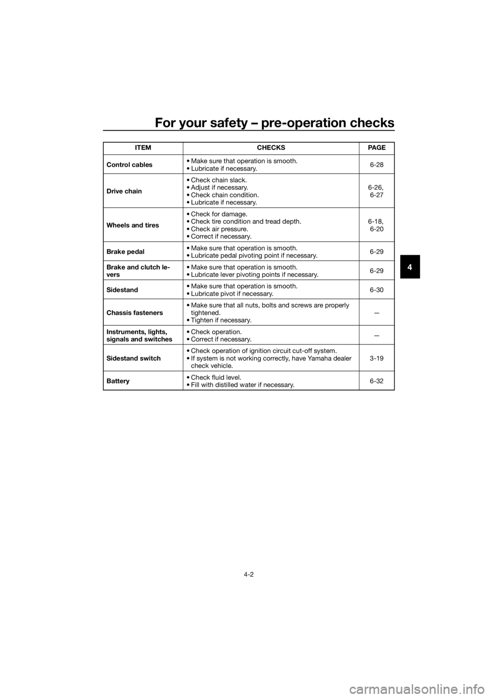
Control cables• Make sure that operation is smooth.
• Lubricate if necessary.6-28
Drive chain• Check chain slack.
• Adjust if necessary.
• Check chain condition.
• Lubricate if necessary.6-26,
6-27
Wheels and tires•Check for damage.
• Check tire condition and tread depth.
• Check air pressure.
• Correct if necessary.6-18,
6-20
Brake pedal• Make sure that operation is smooth.
• Lubricate pedal pivoting point if necessary.6-29
Brake and clutch le-
vers• Make sure that operation is smooth.
• Lubricate lever pivoting points if necessary.6-29
Sidestand• Make sure that operation is smooth.
• Lubricate pivot if necessary.6-30
Chassis fasteners• Make sure that all nuts, bolts and screws are properly
tightened.
• Tighten if necessary.—
Instruments, lights,
signals and switches• Check operation.
• Correct if necessary.—
Sidestand switch • Check operation of ignition circuit cut-off system.
• If system is not working correctly, have Yamaha dealer
check vehicle.3-19
Battery• Check fluid level.
• Fill with distilled water if necessary.6-32 ITEM CHECKS PAGE
U5D7E6E0.book Page 2 Wednesday, June 17, 2015 10:25 AM
Page 80 of 98
Periodic maintenance and adjustment
6-38
6
EAU24351
Supporting the motorcycle
Since this model is not equipped with a
centerstand, follow these precautions
when removing the front and rear
wheel or performing other mainte-
nance requiring the motorcycle to
stand upright. Check that the motorcy-
cle is in a stable and level position be-
fore starting any maintenance. A
strong wooden box can be placed un-
der the engine for added stability.
To service the front wheel
1. Stabilize the rear of the motorcy-
cle by using a motorcycle stand
or, if an additional motorcycle
stand is not available, by placing a
jack under the frame in front of the
rear wheel.
2. Raise the front wheel off the
ground by using a motorcycle
stand.
To service the rear wheel
Raise the rear wheel off the ground by
using a motorcycle stand or, if a motor-
cycle stand is not available, by placing
a jack either under each side of the
frame in front of the rear wheel or under
each side of the swingarm.
EAU44792
Front wheel (for non-ABS
models)
WARNING
EWA14841
For the ABS model, have a Yamaha
dealer remove and install the wheel.
EAU56531
To remove the front wheel
WARNING
EWA10822
To avoid injury, securely support the
vehicle so there is no danger of it
falling over.
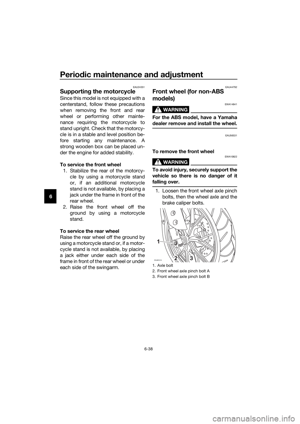
1. Loosen the front wheel axle pinch
bolts, then the wheel axle and the
brake caliper bolts.
1. Axle bolt
2. Front wheel axle pinch bolt A
3. Front wheel axle pinch bolt B
ZAUM12153
U5D7E6E0.book Page 38 Wednesday, June 17, 2015 10:25 AM
Page 81 of 98
Periodic maintenance and adjustment
6-39
6 2. Lift the front wheel off the ground
according to the procedure in the
previous section “Supporting the
motorcycle”.
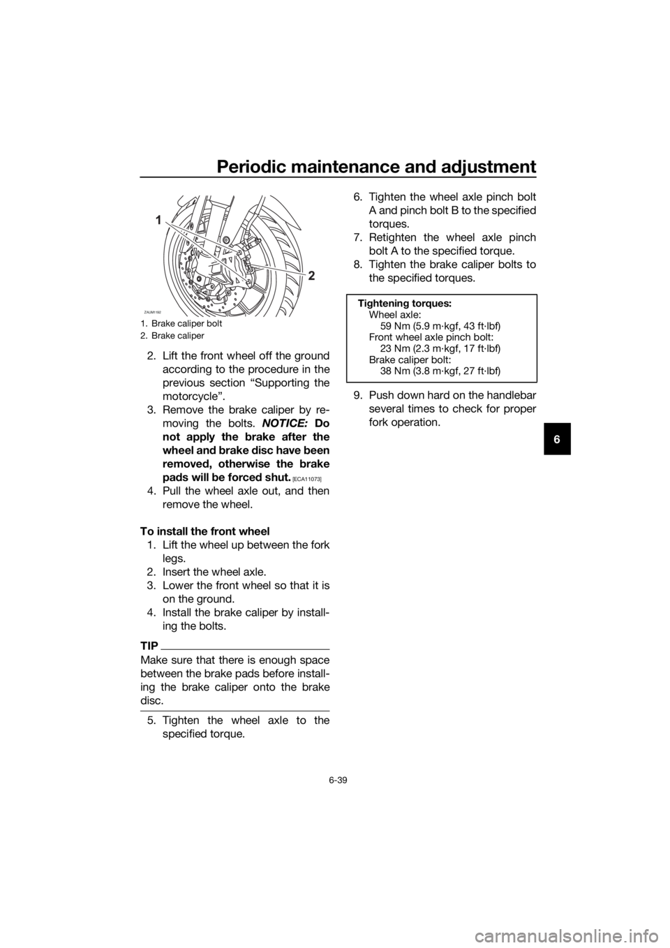
3. Remove the brake caliper by re-
moving the bolts. NOTICE: Do
not apply the brake after the
wheel and brake disc have been
removed, otherwise the brake
pads will be forced shut.
[ECA11073]
4. Pull the wheel axle out, and then
remove the wheel.
To install the front wheel
1. Lift the wheel up between the fork
legs.
2. Insert the wheel axle.
3. Lower the front wheel so that it is
on the ground.
4. Install the brake caliper by install-
ing the bolts.
TIP
Make sure that there is enough space
between the brake pads before install-
ing the brake caliper onto the brake
disc.
5. Tighten the wheel axle to the
specified torque.6. Tighten the wheel axle pinch bolt
A and pinch bolt B to the specified
torques.
7. Retighten the wheel axle pinch
bolt A to the specified torque.
8. Tighten the brake caliper bolts to
the specified torques.
9. Push down hard on the handlebar
several times to check for proper
fork operation.
1. Brake caliper bolt
2. Brake caliper
ZAUM1192Tightening torques:
Wheel axle:
59 Nm (5.9 m·kgf, 43 ft·lbf)
Front wheel axle pinch bolt:
23 Nm (2.3 m·kgf, 17 ft·lbf)
Brake caliper bolt:
38 Nm (3.8 m·kgf, 27 ft·lbf)
U5D7E6E0.book Page 39 Wednesday, June 17, 2015 10:25 AM
Page 82 of 98
Periodic maintenance and adjustment
6-40
6
EAU44802
Rear wheel (for non-ABS
models)
WARNING
EWA14841
For the ABS model, have a Yamaha
dealer remove and install the wheel.
EAU56701
To remove the rear wheel
WARNING
EWA10822
To avoid injury, securely support the
vehicle so there is no danger of it
falling over.
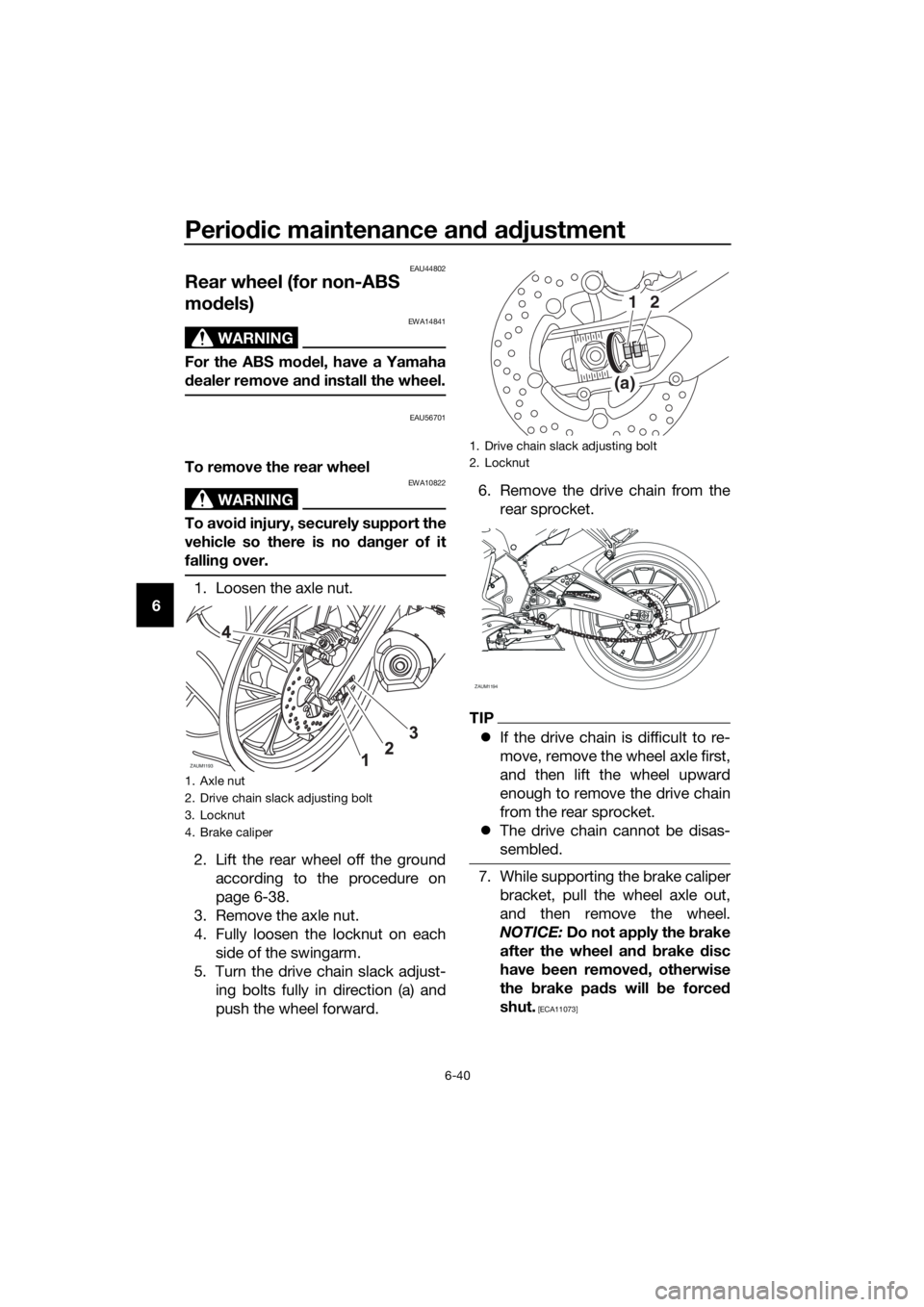
1. Loosen the axle nut.
2. Lift the rear wheel off the ground
according to the procedure on
page 6-38.
3. Remove the axle nut.
4. Fully loosen the locknut on each
side of the swingarm.
5. Turn the drive chain slack adjust-
ing bolts fully in direction (a) and
push the wheel forward.6. Remove the drive chain from the
rear sprocket.
TIP
If the drive chain is difficult to re-
move, remove the wheel axle first,
and then lift the wheel upward
enough to remove the drive chain
from the rear sprocket.
The drive chain cannot be disas-
sembled.
7. While supporting the brake caliper
bracket, pull the wheel axle out,
and then remove the wheel.
NOTICE: Do not apply the brake
after the wheel and brake disc
have been removed, otherwise
the brake pads will be forced
shut.
[ECA11073]
1. Axle nut
2. Drive chain slack adjusting bolt
3. Locknut
4. Brake caliper
ZAUM1193
1. Drive chain slack adjusting bolt
2. Locknut
(a)
12
ZAUM1194
U5D7E6E0.book Page 40 Wednesday, June 17, 2015 10:25 AM