check engine YAMAHA YZF-R125 2017 Owner's Manual
[x] Cancel search | Manufacturer: YAMAHA, Model Year: 2017, Model line: YZF-R125, Model: YAMAHA YZF-R125 2017Pages: 96, PDF Size: 6.43 MB
Page 68 of 96

Periodic maintenance and adjustment
6-26
6
EAU22762
Drive chain slack
The drive chain slack should be
checked before each ride and adjusted
if necessary.
EAUM3551To check the drive chain slack
1. Place the motorcycle on the side-
stand.
TIP
When checking and adjusting the drive
chain slack, there should be no weight
on the motorcycle.
2. Shift the transmission into the
neutral position.
3. Measure the drive chain slack at
the arrow mark on the swingarm
as shown in the illustration.
4. If the drive chain slack is incorrect,
adjust it as follows.
EAU3431ATo adjust the drive chain slack
Consult a Yamaha dealer before ad-
justing the drive chain slack.
1. Loosen the axle nut and the lock-
nut on each side of the swingarm.2. To tighten the drive chain, turn the
drive chain slack adjusting bolt on
each side of the swingarm in di-
rection (a). To loosen the drive
chain, turn the adjusting bolt on
each side of the swingarm in di-
rection (b), and then push the rear
wheel forward. NOTICE: Improp-
er drive chain slack will over-
load the engine as well as other
vital parts of the motorcycle and
can lead to chain slippage or
breakage. To prevent this from
occurring, keep the drive chain
slack within the specified limits.
[ECA10572]
TIP
Using the alignment marks on each
side of the swingarm, make sure that
both drive chain pullers are in the same
position for proper wheel alignment.
3. Tighten the axle nut, then the lock-
nuts to their specified torques.
Drive chain slack:
35.0–45.0 mm (1.38–1.77 in)
1. Drive chain slack
ZAUM1182
1. Axle nut
2. Drive chain slack adjusting bolt
3. Locknut
4. Alignment marks
ZAUM1468
UBR6E0E0.book Page 26 Wednesday, August 17, 2016 1:26 PM
Page 81 of 96

Periodic maintenance and adjustment
6-39
6
EAU68070
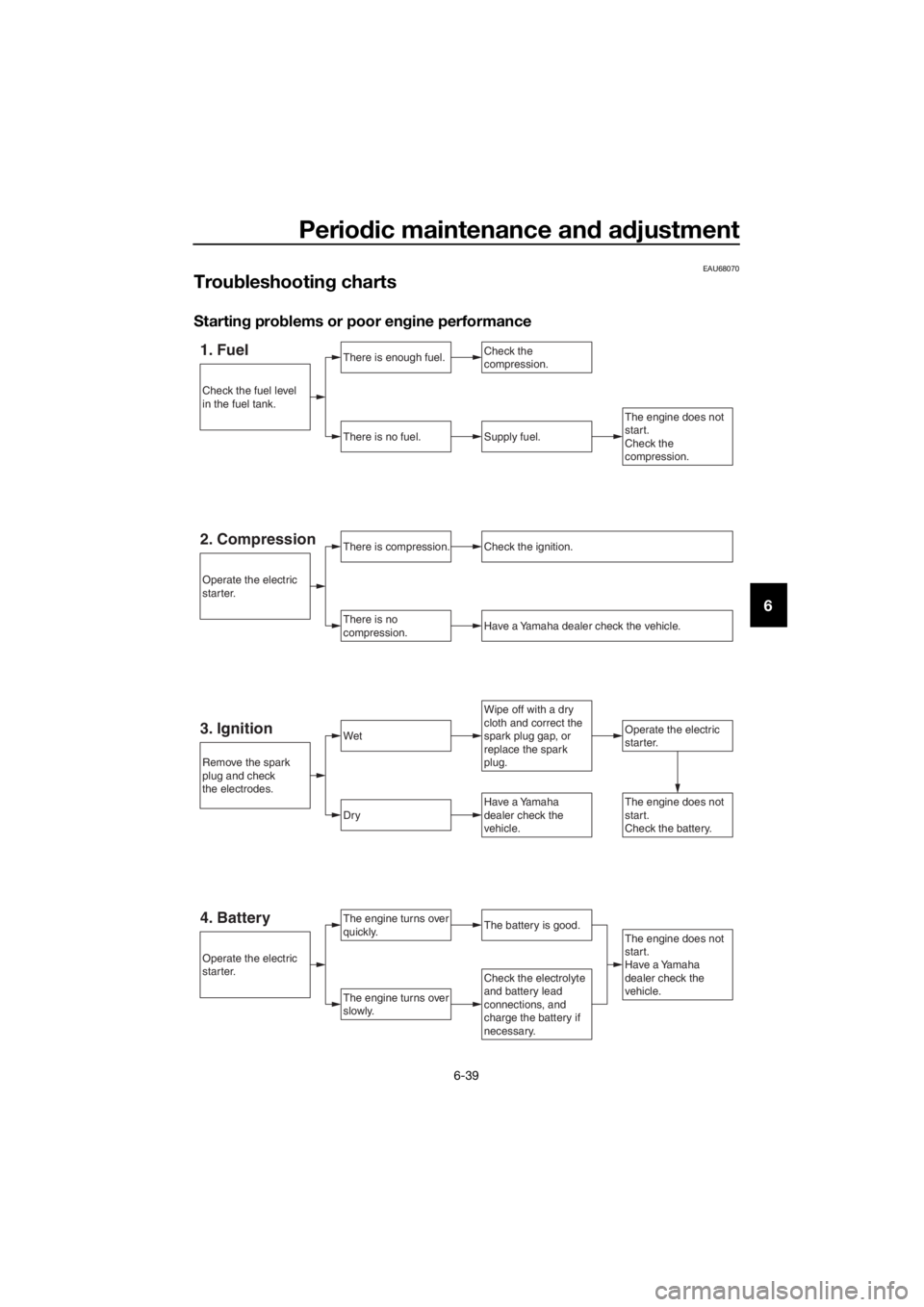
Troubleshooting charts
Starting problems or poor engine performance
1. FuelThere is enough fuel.
There is no fuel.Supply fuel.
The engine turns over
quickly.
Operate the electric
starter.
Check the
compression.
The engine turns over
slowly.
Wipe off with a dry
cloth and correct the
spark plug gap, or
replace the spark
plug.
Check the electrolyte
and battery lead
connections, and
charge the battery if
necessary.
The engine does not
start.
Have a Yamaha
dealer check the
vehicle.
4. BatteryThe battery is good.
3. IgnitionWet
Dry
The engine does not
start.
Check the
compression.
Have a Yamaha
dealer check the
vehicle.The engine does not
start.
Check the battery.
Remove the spark
plug and check
the electrodes.
Check the fuel level
in the fuel tank.
Operate the electric
starter.
Operate the electric
starter.
There is compression.
There is no
compression.Have a Yamaha dealer check the vehicle.
Check the ignition.2. Compression
UBR6E0E0.book Page 39 Wednesday, August 17, 2016 1:26 PM
Page 82 of 96

Periodic maintenance and adjustment
6-40
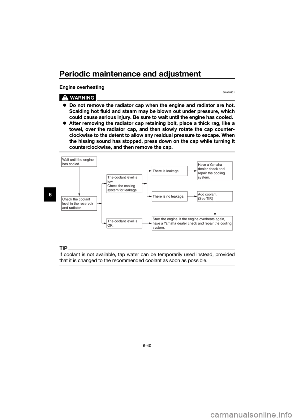
6Engine overheating
WARNING
EWA10401
Do not remove the radiator cap when the engine and radiator are hot.
Scalding hot fluid and steam may be blown out under pressure, which
could cause serious injury. Be sure to wait until the engine has cooled.
After removing the radiator cap retaining bolt, place a thick rag, like a
towel, over the radiator cap, and then slowly rotate the cap counter-
clockwise to the detent to allow any residual pressure to escape. When
the hissing sound has stopped, press down on the cap while turning it
counterclockwise, and then remove the cap.
TIP
If coolant is not available, tap water can be temporarily used instead, provided
that it is changed to the recommended coolant as soon as possible.
Wait until the engine
has cooled.
Check the coolant
level in the reservoir
and radiator.Add coolant.
(See TIP.)
The coolant level is
OK.
There is no leakage.
There is leakage.
The coolant level is
low.
Check the cooling
system for leakage.
Have a Yamaha
dealer check and
repair the cooling
system.
Start the engine. If the engine overheats again,
have a Yamaha dealer check and repair the cooling
system.
UBR6E0E0.book Page 40 Wednesday, August 17, 2016 1:26 PM
Page 86 of 96

Motorcycle care and storage
7-4
7
EAU43204
Storage
Short-term
Always store your motorcycle in a cool,
dry place and, if necessary, protect it
against dust with a porous cover. Be
sure the engine and the exhaust sys-
tem are cool before covering the mo-
torcycle.
NOTICE
ECA10811
Storing the motorcycle in a
poorly ventilated room or cover-
ing it with a tarp, while it is still
wet, will allow water and humid-
ity to seep in and cause rust.
To prevent corrosion, avoid
damp cellars, stables (because
of the presence of ammonia)
and areas where strong chemi-
cals are stored.
Long-term
Before storing your motorcycle for sev-
eral months:
1. Follow all the instructions in the
“Care” section of this chapter.
2. Fill up the fuel tank and add fuel
stabilizer (if available) to prevent
the fuel tank from rusting and the
fuel from deteriorating.
3. Perform the following steps to
protect the cylinder, piston rings,
etc. from corrosion.
a. Remove the spark plug cap
and spark plug.
b. Pour a teaspoonful of engine
oil into the spark plug bore.
c. Install the spark plug cap onto
the spark plug, and then place
the spark plug on the cylinderhead so that the electrodes are
grounded. (This will limit spark-
ing during the next step.)
d. Turn the engine over several
times with the starter. (This will
coat the cylinder wall with oil.)
WARNING! To prevent dam-
age or injury from sparking,
make sure to ground the
spark plug electrodes while
turning the engine over.
[EWA10952]
e. Remove the spark plug cap
from the spark plug, and then
install the spark plug and the
spark plug cap.
4. Lubricate all control cables and
the pivoting points of all levers and
pedals as well as of the side-
stand/centerstand.
5. Check and, if necessary, correct
the tire air pressure, and then lift
the motorcycle so that both of its
wheels are off the ground. Alterna-
tively, turn the wheels a little every
month in order to prevent the tires
from becoming degraded in one
spot.
6. Cover the muffler outlet with a
plastic bag to prevent moisture
from entering it.
7. Remove the battery and fully
charge it. Store it in a cool, dry
place and charge it once a month.
Do not store the battery in an ex-
cessively cold or warm place [less
than 0 °C (30 °F) or more than 30
°C (90 °F)]. For more information
on storing the battery, see page
6-32.
UBR6E0E0.book Page 4 Wednesday, August 17, 2016 1:26 PM
Page 92 of 96

Consumer information
9-2
9
EAUM3880
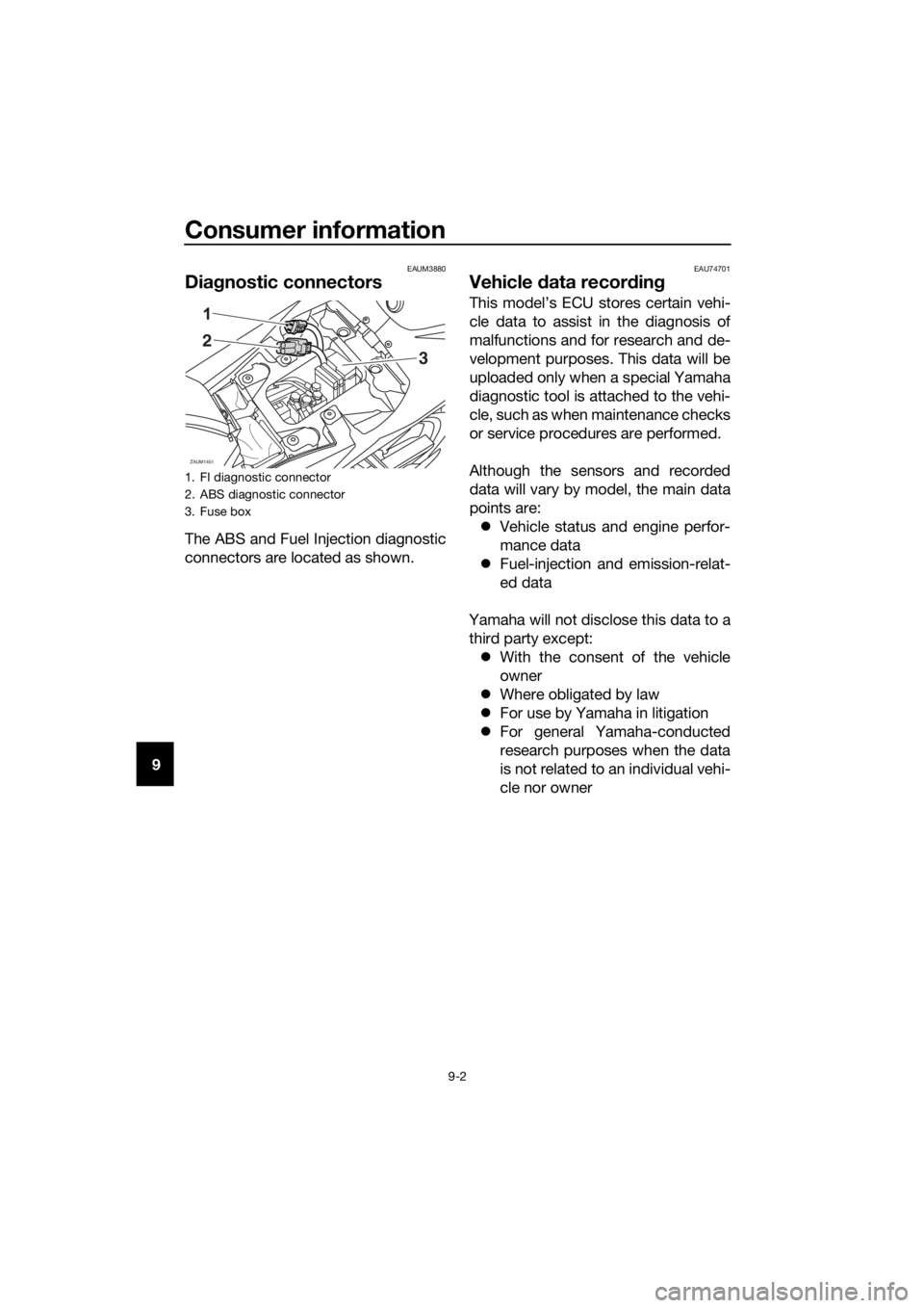
Diagnostic connectors
The ABS and Fuel Injection diagnostic
connectors are located as shown.
EAU74701
Vehicle data recording
This model’s ECU stores certain vehi-
cle data to assist in the diagnosis of
malfunctions and for research and de-
velopment purposes. This data will be
uploaded only when a special Yamaha
diagnostic tool is attached to the vehi-
cle, such as when maintenance checks
or service procedures are performed.
Although the sensors and recorded
data will vary by model, the main data
points are:
Vehicle status and engine perfor-
mance data
Fuel-injection and emission-relat-
ed data
Yamaha will not disclose this data to a
third party except:
With the consent of the vehicle
owner
Where obligated by law
For use by Yamaha in litigation
For general Yamaha-conducted
research purposes when the data
is not related to an individual vehi-
cle nor owner
1. FI diagnostic connector
2. ABS diagnostic connector
3. Fuse box
ZAUM1451
2
3
UBR6E0E0.book Page 2 Wednesday, August 17, 2016 1:26 PM
Page 93 of 96

10-1
10
Index
A
ABS ...................................................... 3-15
ABS warning light ................................... 3-3
Air filter element and check hose,
replacing and cleaning ....................... 6-15
Auxiliary light bulb, replacing ............... 6-35
B
Battery .................................................. 6-32
Brake and clutch levers, checking and
lubricating .......................................... 6-29
Brake fluid, changing ........................... 6-25
Brake fluid level, checking ................... 6-24
Brake lever ........................................... 3-14
Brake light switches ............................. 6-23
Brake pedal .......................................... 3-15
Brake pedal, checking and
lubricating .......................................... 6-29
Brake pedal free play, adjusting........... 6-22
C
Cables, checking and lubricating ......... 6-28
Care ........................................................ 7-1
Catalytic converter ............................... 3-18
Clutch lever .......................................... 3-13
Clutch lever free play, adjusting ........... 6-21
Coolant ................................................. 6-14
Cowlings and panel, removing and
installing ............................................... 6-7
D
Data recording, vehicle .......................... 9-2
Diagnostic connectors ........................... 9-2
Dimmer switch ..................................... 3-12
Drive chain, cleaning and lubricating ... 6-27
Drive chain slack .................................. 6-26
E
Engine break-in ...................................... 5-4
Engine idling speed, checking ............. 6-16
Engine oil and oil filter element ............ 6-11
Engine stop switch ............................... 3-12
Engine trouble warning light................... 3-3
F
Front and rear brake pads, checking ... 6-23
Front brake lever free play, checking ... 6-22
Front fork, checking ............................. 6-31
Fuel....................................................... 3-17
Fuel consumption, tips for reducing ...... 5-4
Fuel level warning light ........................... 3-2
Fuel tank cap........................................ 3-16
Fuses, replacing ................................... 6-34
H
Handlebar switches.............................. 3-12Headlight bulb, replacing ...................... 6-35
High beam indicator light........................ 3-2
Horn switch........................................... 3-12
I
Identification numbers ............................ 9-1
Ignition circuit cut-off system ............... 3-20
Indicator lights and warning lights .......... 3-2
Info switch ............................................ 3-12
L
License plate light bulb, replacing ........ 6-37
M
Main switch/steering lock ....................... 3-1
Maintenance and lubrication, periodic ... 6-4
Maintenance, emission control
system .................................................. 6-3
Matte color, caution ................................ 7-1
Model label ............................................. 9-1
Multi-function meter unit ........................ 3-4
N
Neutral indicator light.............................. 3-2
P
Parking .................................................... 5-5
Part locations .......................................... 2-1
Pass switch........................................... 3-12
R
Rider seat.............................................. 3-19
S
Safety information................................... 1-1
Shifting .................................................... 5-3
Shift pedal............................................. 3-14
Sidestand .............................................. 3-20
Sidestand, checking and lubricating .... 6-30
Spark plug, checking .............................. 6-9
Specifications ......................................... 8-1
Starting the engine.................................. 5-2
Start switch ........................................... 3-12
Steering, checking ................................ 6-31
Storage ................................................... 7-4
Supporting the motorcycle ................... 6-37
Swingarm pivots, lubricating ................ 6-30
T
Tail/brake light ...................................... 6-36
Throttle grip and cable, checking and
lubricating ........................................... 6-28
Throttle grip free play, adjusting ........... 6-16
Tires ...................................................... 6-18
Tool kit .................................................... 6-2
Troubleshooting .................................... 6-38
Troubleshooting charts ......................... 6-39
Turn signal indicator light ....................... 3-2
UBR6E0E0.book Page 1 Wednesday, August 17, 2016 1:26 PM