warning lights YAMAHA YZF-R125 2019 Owners Manual
[x] Cancel search | Manufacturer: YAMAHA, Model Year: 2019, Model line: YZF-R125, Model: YAMAHA YZF-R125 2019Pages: 96, PDF Size: 5.65 MB
Page 5 of 96

Table of contents
Safety information............................1-1
Description........................................2-1
Left view ..........................................2-1
Right view........................................2-2
Controls and instruments ................2-3
Instrument and control functions....3-1
Main switch/steering lock ...............3-1
Indicator lights and warning
lights ............................................3-2
Multi-function meter unit .................3-4
Handlebar switches.......................3-12
Clutch lever ...................................3-13
Shift pedal .....................................3-13
Brake lever ....................................3-14
Brake pedal ...................................3-14
ABS ...............................................3-15
Fuel tank cap.................................3-16
Fuel................................................3-16
Fuel tank overflow hose ................3-18
Catalytic converter ........................3-18
Seats .............................................3-19
Sidestand ......................................3-20
Ignition circuit cut-off system........3-21
For your safety – pre-operation
checks...............................................4-1
Operation and important riding
points.................................................5-1
Starting the engine ..........................5-2
Shifting ............................................5-3
Tips for reducing fuel
consumption ................................5-4
Engine break-in ...............................5-4
Parking ............................................5-5
Periodic maintenance and
adjustment........................................6-1
Owner’s tool kit ...............................6-2
Periodic maintenance chart for the
emission control system ..............6-3
General maintenance and
lubrication chart ...........................6-4
Removing and installing cowlings ...6-7Checking the spark plug ................. 6-9
Engine oil and oil filter element ..... 6-10
Why Yamalube .............................. 6-12
Coolant ......................................... 6-13
Replacing the air filter element
and cleaning the check hose..... 6-14
Adjusting the engine idling
speed......................................... 6-15
Adjusting the throttle grip free
play ............................................ 6-15
Valve clearance ............................. 6-16
Tires .............................................. 6-17
Cast wheels .................................. 6-19
Adjusting the clutch lever free
play ............................................ 6-20
Checking the front brake lever
free play ..................................... 6-21
Adjusting the brake pedal free
play ............................................ 6-21
Brake light switches ...................... 6-22
Checking the front and rear brake
pads........................................... 6-22
Checking the brake fluid level....... 6-23
Changing the brake fluid............... 6-24
Drive chain slack ........................... 6-25
Cleaning and lubricating the drive
chain .......................................... 6-26
Checking and lubricating the
cables ........................................ 6-27
Checking and lubricating the
throttle grip and cable ............... 6-27
Checking and lubricating the
brake and shift pedals ............... 6-28
Checking and lubricating the
brake and clutch levers ............. 6-28
Checking and lubricating the
sidestand ................................... 6-29
Lubricating the swingarm pivots... 6-29
Checking the front fork ................. 6-30
Checking the steering ................... 6-30
Checking the wheel bearings ....... 6-31
Battery .......................................... 6-31
Replacing the fuses ...................... 6-33
Vehicle lights ................................. 6-34
Tail/brake light .............................. 6-34
UB5GE0E0.book Page 1 Thursday, August 23, 2018 10:05 AM
Page 15 of 96
Instrument and control functions
3-1
3
EAU10462
Main switch/steering lock
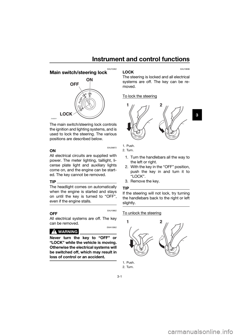
The main switch/steering lock controls
the ignition and lighting systems, and is
used to lock the steering. The various
positions are described below.
EAU36872ON
All electrical circuits are supplied with
power. The meter lighting, taillight, li-
cense plate light and auxiliary lights
come on, and the engine can be start-
ed. The key cannot be removed.
TIP
The headlight comes on automatically
when the engine is started and stays
even if the engine stalls.
EAU10662OFF
All electrical systems are off. The key
can be removed.
WARNING
EWA10062
Never turn the key to “OFF” or
“LOCK” while the vehicle is moving.
Otherwise the electrical systems will
be switched off, which may result in
loss of control or an accident.
EAU10696LOCK
The steering is locked and all electrical
systems are off. The key can be re-
moved.
To lock the steering
1. Turn the handlebars all the way to
the left or right.
2. With the key in the “OFF” position,
push the key in and turn it to
“LOCK”.
3. Remove the key.
TIP
If the steering will not lock, try turning
the handlebars back to the right or left
slightly.
To unlock the steering
ZAUE0971
1. Push.
2. Turn.
1. Push.
2. Turn.
12
12
UB5GE0E0.book Page 1 Thursday, August 23, 2018 10:05 AM
Page 16 of 96
Instrument and control functions
3-2
3From the “LOCK” position, push the
key and turn it to “OFF”.
EAU4939G
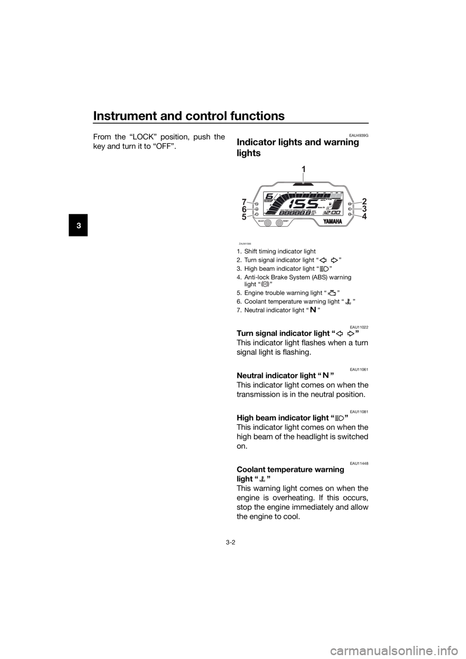
Indicator lights and warning
lights
EAU11022Turn signal indicator light “ ”
This indicator light flashes when a turn
signal light is flashing.
EAU11061Neutral indicator light “ ”
This indicator light comes on when the
transmission is in the neutral position.
EAU11081High beam indicator light “ ”
This indicator light comes on when the
high beam of the headlight is switched
on.
EAU11448Coolant temperature warning
light “ ”
This warning light comes on when the
engine is overheating. If this occurs,
stop the engine immediately and allow
the engine to cool.
1. Shift timing indicator light
2. Turn signal indicator light “ ”
3. High beam indicator light “ ”
4. Anti-lock Brake System (ABS) warning
light “ ”
5. Engine trouble warning light “ ”
6. Coolant temperature warning light “ ”
7. Neutral indicator light “ ”
ZAUM1566
56 72
3
4
1
ABS
UB5GE0E0.book Page 2 Thursday, August 23, 2018 10:05 AM
Page 26 of 96
Instrument and control functions
3-12
3
EAU1234M
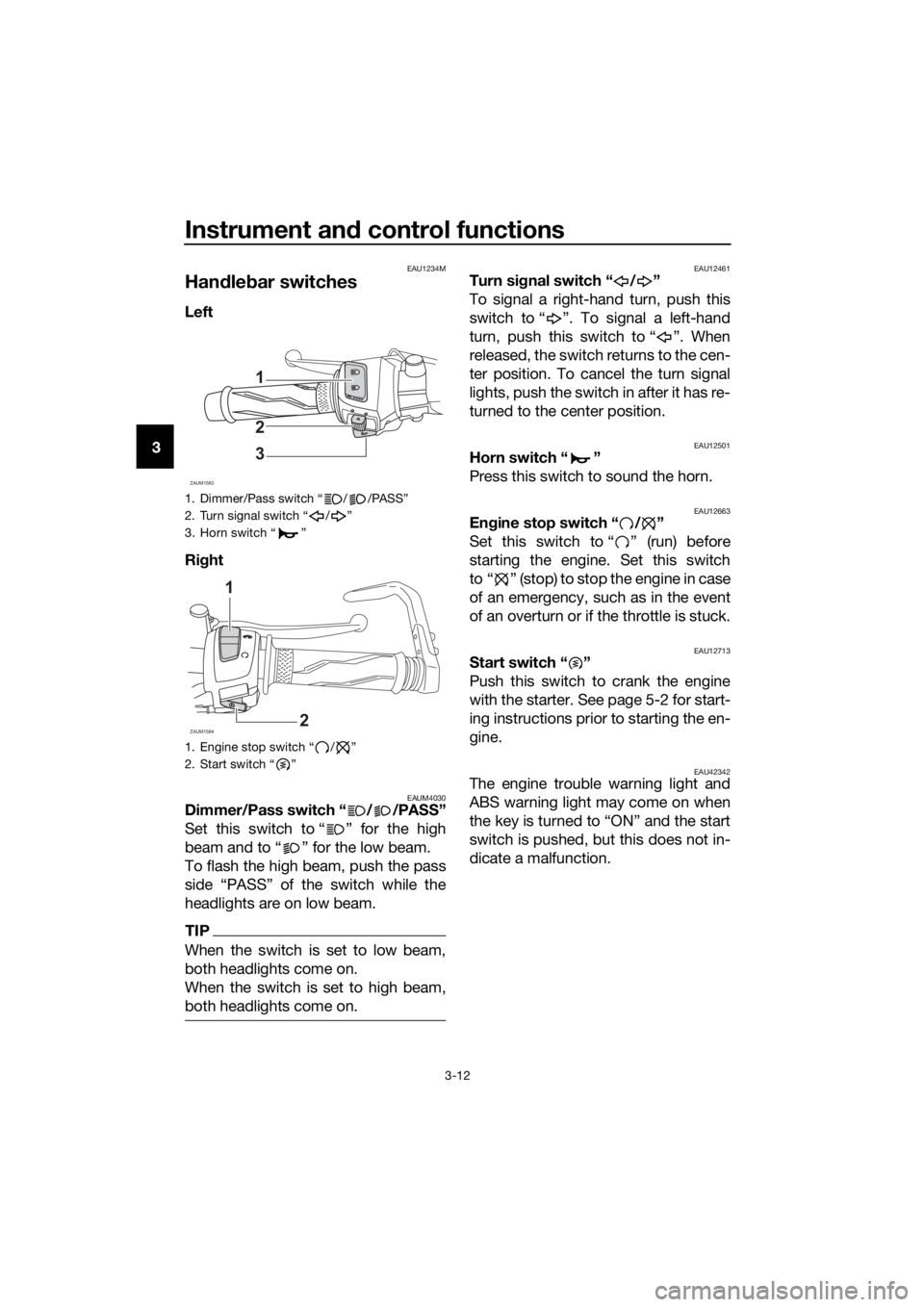
Handlebar switches
Left
Right
EAUM4030Dimmer/Pass switch “ / /PASS”
Set this switch to “ ” for the high
beam and to “ ” for the low beam.
To flash the high beam, push the pass
side “PASS” of the switch while the
headlights are on low beam.
TIP
When the switch is set to low beam,
both headlights come on.
When the switch is set to high beam,
both headlights come on.
EAU12461Turn signal switch “ / ”
To signal a right-hand turn, push this
switch to “ ”. To signal a left-hand
turn, push this switch to “ ”. When
released, the switch returns to the cen-
ter position. To cancel the turn signal
lights, push the switch in after it has re-
turned to the center position.
EAU12501Horn switch “ ”
Press this switch to sound the horn.
EAU12663Engine stop switch “ / ”
Set this switch to “ ” (run) before
starting the engine. Set this switch
to “ ” (stop) to stop the engine in case
of an emergency, such as in the event
of an overturn or if the throttle is stuck.
EAU12713Start switch “ ”
Push this switch to crank the engine
with the starter. See page 5-2 for start-
ing instructions prior to starting the en-
gine.
EAU42342The engine trouble warning light and
ABS warning light may come on when
the key is turned to “ON” and the start
switch is pushed, but this does not in-
dicate a malfunction.
1. Dimmer/Pass switch “ / /PASS”
2. Turn signal switch “ / ”
3. Horn switch “ ”
1. Engine stop switch “ / ”
2. Start switch “ ”
ZAUM1583
1
2
3
ZAUM1584
1
2
UB5GE0E0.book Page 12 Thursday, August 23, 2018 10:05 AM
Page 30 of 96
Instrument and control functions
3-16
3
EAU13076
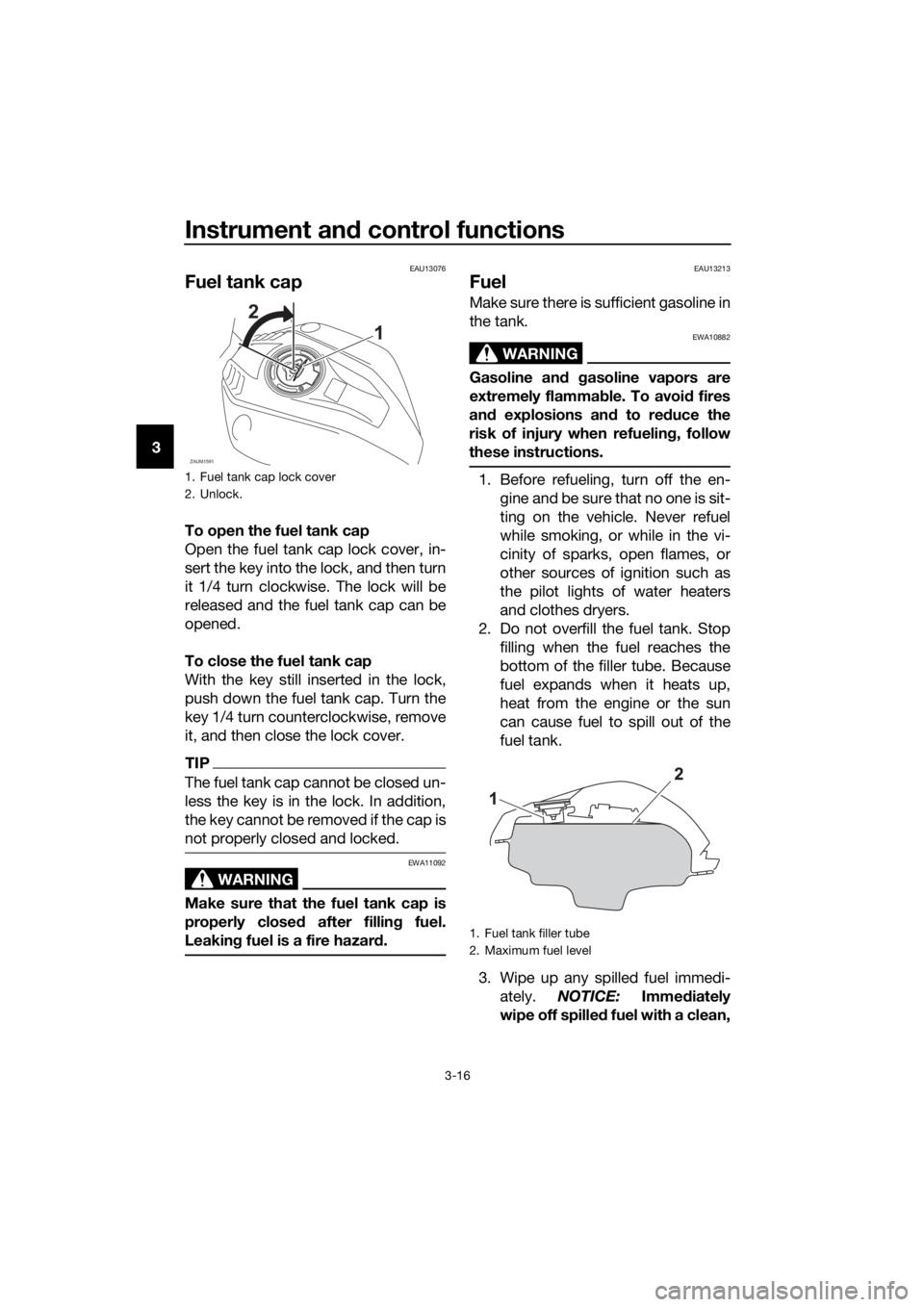
Fuel tank cap
To open the fuel tank cap
Open the fuel tank cap lock cover, in-
sert the key into the lock, and then turn
it 1/4 turn clockwise. The lock will be
released and the fuel tank cap can be
opened.
To close the fuel tank cap
With the key still inserted in the lock,
push down the fuel tank cap. Turn the
key 1/4 turn counterclockwise, remove
it, and then close the lock cover.
TIP
The fuel tank cap cannot be closed un-
less the key is in the lock. In addition,
the key cannot be removed if the cap is
not properly closed and locked.
WARNING
EWA11092
Make sure that the fuel tank cap is
properly closed after filling fuel.
Leaking fuel is a fire hazard.
EAU13213
Fuel
Make sure there is sufficient gasoline in
the tank.
WARNING
EWA10882
Gasoline and gasoline vapors are
extremely flammable. To avoid fires
and explosions and to reduce the
risk of injury when refueling, follow
these instructions.
1. Before refueling, turn off the en-
gine and be sure that no one is sit-
ting on the vehicle. Never refuel
while smoking, or while in the vi-
cinity of sparks, open flames, or
other sources of ignition such as
the pilot lights of water heaters
and clothes dryers.
2. Do not overfill the fuel tank. Stop
filling when the fuel reaches the
bottom of the filler tube. Because
fuel expands when it heats up,
heat from the engine or the sun
can cause fuel to spill out of the
fuel tank.
3. Wipe up any spilled fuel immedi-
ately. NOTICE: Immediately
wipe off spilled fuel with a clean,1. Fuel tank cap lock cover
2. Unlock.
ZAUM1591
2
1
1. Fuel tank filler tube
2. Maximum fuel level
UB5GE0E0.book Page 16 Thursday, August 23, 2018 10:05 AM
Page 40 of 96
Operation and important riding points
5-2
5
EAUM4021
Starting the engine
Under normal conditions, shift the
transmission into neutral before start-
ing the engine. To start the engine with
the transmission in gear, the sidestand
must be up and the clutch lever pulled.
To start the engine
1. Set the engine stop switch to the
run position, and turn the main
switch to the on position.
2. Confirm the following lights come
on for a few seconds and then go
off.
Engine trouble warning light
Coolant warning light
Shift timing indicator light
TIP
The ABS warning light should go
off after reaching a speed of 10
km/h (6 mi/h) or higher.
The neutral position indicator light
should be on when the transmis-
sion is in neutral.
NOTICE
ECA24110
If a warning or indicator light does
not work as described above, have a
Yamaha dealer check the vehicle.
3. Shift the transmission into neutral.
4. Push the start switch to crank the
engine with the starter.
Release the start switch when the
engine starts, or after 5 seconds.
Wait 10 seconds before pressing
the switch again to allow battery
voltage to restore.
NOTICE
ECA11043
For maximum engine life, never ac-
celerate hard when the engine is
cold!
UB5GE0E0.book Page 2 Thursday, August 23, 2018 10:05 AM
Page 79 of 96
Periodic maintenance and adjustment
6-36
6
EAU67131
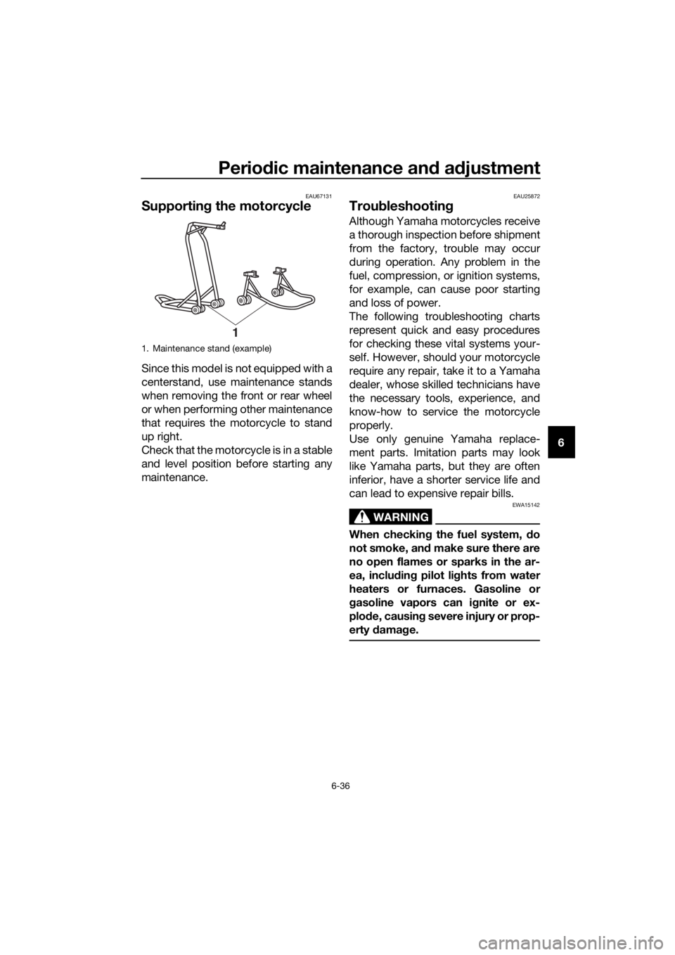
Supporting the motorcycle
Since this model is not equipped with a
centerstand, use maintenance stands
when removing the front or rear wheel
or when performing other maintenance
that requires the motorcycle to stand
up right.
Check that the motorcycle is in a stable
and level position before starting any
maintenance.
EAU25872
Troubleshooting
Although Yamaha motorcycles receive
a thorough inspection before shipment
from the factory, trouble may occur
during operation. Any problem in the
fuel, compression, or ignition systems,
for example, can cause poor starting
and loss of power.
The following troubleshooting charts
represent quick and easy procedures
for checking these vital systems your-
self. However, should your motorcycle
require any repair, take it to a Yamaha
dealer, whose skilled technicians have
the necessary tools, experience, and
know-how to service the motorcycle
properly.
Use only genuine Yamaha replace-
ment parts. Imitation parts may look
like Yamaha parts, but they are often
inferior, have a shorter service life and
can lead to expensive repair bills.
WARNING
EWA15142
When checking the fuel system, do
not smoke, and make sure there are
no open flames or sparks in the ar-
ea, including pilot lights from water
heaters or furnaces. Gasoline or
gasoline vapors can ignite or ex-
plode, causing severe injury or prop-
erty damage.
1. Maintenance stand (example)
1
UB5GE0E0.book Page 36 Thursday, August 23, 2018 10:05 AM
Page 92 of 96

10-1
10
Index
A
ABS ....................................................... 3-15
ABS warning light ................................... 3-3
Air filter element and check hose,
replacing and cleaning ....................... 6-14
B
Battery .................................................. 6-31
Brake and clutch levers, checking and
lubricating ........................................... 6-28
Brake and shift pedals, checking and
lubricating ........................................... 6-28
Brake fluid, changing ............................ 6-24
Brake fluid level, checking .................... 6-23
Brake lever ............................................ 3-14
Brake light switches.............................. 6-22
Brake pedal........................................... 3-14
Brake pedal free play, adjusting ........... 6-21
C
Cables, checking and lubricating ......... 6-27
Care ........................................................ 7-1
Catalytic converter ................................ 3-18
Clutch lever ........................................... 3-13
Clutch lever free play, adjusting ........... 6-20
Coolant ................................................. 6-13
Coolant temperature warning light ......... 3-2
Cowlings, removing and installing .......... 6-7
D
Data recording, vehicle ........................... 9-3
Diagnostic connectors ............................ 9-2
Dimmer/Pass switch ............................. 3-12
Drive chain, cleaning and lubricating .... 6-26
Drive chain slack................................... 6-25
E
Engine break-in....................................... 5-4
Engine idling speed .............................. 6-15
Engine oil and oil filter element ............. 6-10
Engine serial number .............................. 9-1
Engine stop switch ............................... 3-12
Engine trouble warning light ................... 3-3
F
Front and rear brake pads, checking.... 6-22
Front brake lever free play, checking ... 6-21
Front fork, checking .............................. 6-30
Fuel ....................................................... 3-16
Fuel consumption, tips for reducing ....... 5-4
Fuel tank cap ........................................ 3-16
Fuel tank overflow hose ........................ 3-18
Fuses, replacing.................................... 6-33
H
Handlebar switches .............................. 3-12High beam indicator light ....................... 3-2
Horn switch .......................................... 3-12
I
Identification numbers ............................ 9-1
Ignition circuit cut-off system............... 3-21
Indicator lights and warning lights ......... 3-2
L
License plate light bulb, replacing........ 6-35
M
Main switch/steering lock....................... 3-1
Maintenance and lubrication, periodic ... 6-4
Maintenance, emission control
system.................................................. 6-3
Matte color, caution ............................... 7-1
Model label ............................................. 9-1
Multi-function meter unit ........................ 3-4
N
Neutral indicator light ............................. 3-2
P
Parking ................................................... 5-5
Part locations ......................................... 2-1
S
Safety information .................................. 1-1
Seats .................................................... 3-19
Shifting ................................................... 5-3
Shift pedal ............................................ 3-13
Shift timing indicator light....................... 3-3
Sidestand ............................................. 3-20
Sidestand, checking and lubricating .... 6-29
Spark plug, checking ............................. 6-9
Specifications ......................................... 8-1
Starting the engine ................................. 5-2
Start switch .......................................... 3-12
Steering, checking................................ 6-30
Storage ................................................... 7-4
Supporting the motorcycle................... 6-36
Swingarm pivots, lubricating ................ 6-29
T
Tail/brake light ...................................... 6-34
Throttle grip and cable, checking and
lubricating .......................................... 6-27
Throttle grip free play, adjusting........... 6-15
Tires ...................................................... 6-17
Tool kit.................................................... 6-2
Troubleshooting ................................... 6-36
Troubleshooting charts ........................ 6-37
Turn signal indicator light ....................... 3-2
Turn signal light bulb, replacing ........... 6-35
Turn signal switch ................................ 3-12
UB5GE0E0.book Page 1 Thursday, August 23, 2018 10:05 AM