wheel YAMAHA YZF-R125 2019 Owners Manual
[x] Cancel search | Manufacturer: YAMAHA, Model Year: 2019, Model line: YZF-R125, Model: YAMAHA YZF-R125 2019Pages: 96, PDF Size: 5.65 MB
Page 5 of 96

Table of contents
Safety information............................1-1
Description........................................2-1
Left view ..........................................2-1
Right view........................................2-2
Controls and instruments ................2-3
Instrument and control functions....3-1
Main switch/steering lock ...............3-1
Indicator lights and warning
lights ............................................3-2
Multi-function meter unit .................3-4
Handlebar switches.......................3-12
Clutch lever ...................................3-13
Shift pedal .....................................3-13
Brake lever ....................................3-14
Brake pedal ...................................3-14
ABS ...............................................3-15
Fuel tank cap.................................3-16
Fuel................................................3-16
Fuel tank overflow hose ................3-18
Catalytic converter ........................3-18
Seats .............................................3-19
Sidestand ......................................3-20
Ignition circuit cut-off system........3-21
For your safety – pre-operation
checks...............................................4-1
Operation and important riding
points.................................................5-1
Starting the engine ..........................5-2
Shifting ............................................5-3
Tips for reducing fuel
consumption ................................5-4
Engine break-in ...............................5-4
Parking ............................................5-5
Periodic maintenance and
adjustment........................................6-1
Owner’s tool kit ...............................6-2
Periodic maintenance chart for the
emission control system ..............6-3
General maintenance and
lubrication chart ...........................6-4
Removing and installing cowlings ...6-7Checking the spark plug ................. 6-9
Engine oil and oil filter element ..... 6-10
Why Yamalube .............................. 6-12
Coolant ......................................... 6-13
Replacing the air filter element
and cleaning the check hose..... 6-14
Adjusting the engine idling
speed......................................... 6-15
Adjusting the throttle grip free
play ............................................ 6-15
Valve clearance ............................. 6-16
Tires .............................................. 6-17
Cast wheels .................................. 6-19
Adjusting the clutch lever free
play ............................................ 6-20
Checking the front brake lever
free play ..................................... 6-21
Adjusting the brake pedal free
play ............................................ 6-21
Brake light switches ...................... 6-22
Checking the front and rear brake
pads........................................... 6-22
Checking the brake fluid level....... 6-23
Changing the brake fluid............... 6-24
Drive chain slack ........................... 6-25
Cleaning and lubricating the drive
chain .......................................... 6-26
Checking and lubricating the
cables ........................................ 6-27
Checking and lubricating the
throttle grip and cable ............... 6-27
Checking and lubricating the
brake and shift pedals ............... 6-28
Checking and lubricating the
brake and clutch levers ............. 6-28
Checking and lubricating the
sidestand ................................... 6-29
Lubricating the swingarm pivots... 6-29
Checking the front fork ................. 6-30
Checking the steering ................... 6-30
Checking the wheel bearings ....... 6-31
Battery .......................................... 6-31
Replacing the fuses ...................... 6-33
Vehicle lights ................................. 6-34
Tail/brake light .............................. 6-34
UB5GE0E0.book Page 1 Thursday, August 23, 2018 10:05 AM
Page 8 of 96

Safety information
1-2
1Many accidents involve inexperi-
enced operators. In fact, many op-
erators who have been involved in
accidents do not even have a cur-
rent motorcycle license.
• Make sure that you are qualified
and that you only lend your mo-
torcycle to other qualified oper-
ators.
• Know your skills and limits.
Staying within your limits may
help you to avoid an accident.
• We recommend that you prac-
tice riding your motorcycle
where there is no traffic until you
have become thoroughly famil-
iar with the motorcycle and all of
its controls.
Many accidents have been
caused by error of the motorcycle
operator. A typical error made by
the operator is veering wide on a
turn due to excessive speed or un-
dercornering (insufficient lean an-
gle for the speed).
• Always obey the speed limit and
never travel faster than warrant-
ed by road and traffic condi-
tions.
• Always signal before turning or
changing lanes. Make sure that
other motorists can see you.
The posture of the operator and
passenger is important for proper
control.
• The operator should keep both
hands on the handlebar and
both feet on the operator foot-
rests during operation to main-
tain control of the motorcycle.• The passenger should always
hold onto the operator, the seat
strap or grab bar, if equipped,
with both hands and keep both
feet on the passenger footrests.
Never carry a passenger unless
he or she can firmly place both
feet on the passenger footrests.
Never ride under the influence of
alcohol or other drugs.
This motorcycle is designed for
on-road use only. It is not suitable
for off-road use.
Protective Apparel
The majority of fatalities from motorcy-
cle accidents are the result of head in-
juries. The use of a safety helmet is the
single most critical factor in the pre-
vention or reduction of head injuries.
Always wear an approved helmet.
Wear a face shield or goggles.
Wind in your unprotected eyes
could contribute to an impairment
of vision that could delay seeing a
hazard.
The use of a jacket, heavy boots,
trousers, gloves, etc., is effective
in preventing or reducing abra-
sions or lacerations.
Never wear loose-fitting clothes,
otherwise they could catch on the
control levers, footrests, or wheels
and cause injury or an accident.
Always wear protective clothing
that covers your legs, ankles, and
feet. The engine or exhaust sys-
tem become very hot during or af-
ter operation and can cause
burns.
A passenger should also observe
the above precautions.
UB5GE0E0.book Page 2 Thursday, August 23, 2018 10:05 AM
Page 17 of 96
Instrument and control functions
3-3
3 When the vehicle is turned on, the light
will come on for a few seconds, and
then go off. If the light does not come
on, or if the light remains on, have a
Yamaha dealer check the vehicle.
TIP
For vehicles with a radiator fan,
the radiator fan(s) automatically
switch on or off according to the
coolant temperature.
If the engine overheats, see page
6-38 for further instructions.
NOTICE
ECA10022
Do not continue to operate the en-
gine if it is overheating.
EAU11487Engine trouble warning light “ ”
This warning light comes on if a prob-
lem is detected in the engine. If this oc-
curs, have a Yamaha dealer check the
vehicle as soon as possible.
TIP
When the vehicle is turned on, the light
should come for a few seconds and
then go off. Otherwise, have a Yamaha
dealer check the electrical circuit.
EAU69892ABS warning light “ ”
This warning light comes on when the
vehicle is first turned on, and goes off
after starting riding. If the warning light
comes on while riding, the anti-lock
brake system may not work correctly.
(See page 3-15.)
TIP
If the light does not come at all, or if the
light does not go off after traveling 10
km/h (6 mi/h), have a Yamaha dealer
check the vehicle.
WARNING
EWA16041
If the ABS warning light does not go
off after traveling at a speed of 10
km/h (6 mi/h) or higher, or if the
warning light comes on or flashes
while riding, the brake system re-
verts to conventional braking. If ei-
ther of the above occurs, or if the
warning light does not come on at
all, use extra caution to avoid possi-
ble wheel lock during emergency
braking. Have a Yamaha dealer
check the brake system and electri-
cal circuits as soon as possible.
EAU11575Shift timing indicator light
This indicator light can be set to come
on and go off at the desired engine
speeds and is used to inform the rider
when it is time to shift to the next high-
er gear.
The electrical circuit of the indicator
light can be checked by turning the key
to “ON”. The indicator light should
come on for a few seconds, and then
go off.
If the indicator light does not come on
initially when the key is turned to “ON”,
or if the indicator light remains on, have
a Yamaha dealer check the electrical
circuit. (See page 3-9 for a detailed ex-
planation of the function of this indica-
tor light and on how to set it.)
ABS
UB5GE0E0.book Page 3 Thursday, August 23, 2018 10:05 AM
Page 29 of 96
Instrument and control functions
3-15
3
EAU63040
ABS
The Yamaha ABS (Anti-lock Brake
System) features a dual electronic con-
trol system, which acts on the front and
rear brakes independently.
Operate the brakes with ABS as you
would conventional brakes. If the ABS
is activated, a pulsating sensation may
be felt at the brake lever or brake ped-
al. In this situation, continue to apply
the brakes and let the ABS work; do
not “pump” the brakes as this will re-
duce braking effectiveness.
WARNING
EWA16051
Always keep a sufficient distance
from the vehicle ahead to match the
riding speed even with ABS.
The ABS performs best with
long braking distances.
On certain surfaces, such as
rough or gravel roads, the brak-
ing distance may be longer with
the ABS than without.
The ABS is monitored by an ECU,
which will revert the system to conven-
tional braking if a malfunction occurs.
TIP
The ABS performs a self-diagno-
sis test each time the vehicle first
starts off after the key is turned to
“ON” and the vehicle has traveled
at a speed of 10 km/h (6 mi/h) or
higher. During this test, a “click-
ing” noise can be heard from the
hydraulic control unit, and if the
brake lever or brake pedal is even
slightly applied, a vibration can be
felt at the lever and pedal, but
these do not indicate a malfunc-
tion.This ABS has a test mode which
allows the owner to experience
the pulsation at the brake lever or
brake pedal when the ABS is op-
erating. However, special tools are
required, so please consult your
Yamaha dealer.
NOTICE
ECA20100
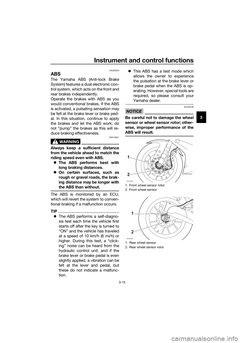
Be careful not to damage the wheel
sensor or wheel sensor rotor; other-
wise, improper performance of the
ABS will result.
1. Front wheel sensor rotor
2. Front wheel sensor
1. Rear wheel sensor
2. Rear wheel sensor rotor
ZAUM1589
1
2
ZAUM1590
1
2
UB5GE0E0.book Page 15 Thursday, August 23, 2018 10:05 AM
Page 38 of 96

For your safety – pre-operation checks
4-2
4
Throttle grip• Make sure that operation is smooth.
• Check throttle grip free play.
• If necessary, have Yamaha dealer adjust throttle grip
free play and lubricate cable and grip housing.6-15,
6-27
Control cables• Make sure that operation is smooth.
• Lubricate if necessary.6-27
Drive chain• Check chain slack.
• Adjust if necessary.
• Check chain condition.
• Lubricate if necessary.6-25,
6-26
Wheels and tires•Check for damage.
• Check tire condition and tread depth.
• Check air pressure.
• Correct if necessary.6-17,
6-19
Brake and shift pedals• Make sure that operation is smooth.
• Lubricate pedal pivoting points if necessary.6-28
Brake and clutch le-
vers• Make sure that operation is smooth.
• Lubricate lever pivoting points if necessary.6-28
Sidestand• Make sure that operation is smooth.
• Lubricate pivot if necessary.6-29
Chassis fasteners• Make sure that all nuts, bolts and screws are properly
tightened.
• Tighten if necessary.—
Instruments, lights,
signals and switches• Check operation.
• Correct if necessary.—
Sidestand switch • Check operation of ignition circuit cut-off system.
• If system is not working correctly, have Yamaha dealer
check vehicle.3-20 ITEM CHECKS PAGE
UB5GE0E0.book Page 2 Thursday, August 23, 2018 10:05 AM
Page 47 of 96

Periodic maintenance and adjustment
6-4
6
EAU71361
General maintenance and lubrication chart
NO. ITEM
1*Diagnostic system
check• Perform dynamic inspection us-
ing Yamaha diagnostic tool.
• Check the error codes.√√√√√√
2*Air filter element• Clean.√√
• Replace.√√
3Air filter case
check hose• Clean.√√√√√
4*Battery• Check electrolyte level and spe-
cific gravity.
• Make sure that the breather
hose is properly routed.√√√√√
5Clutch• Check operation.
•Adjust.√√√√√
6*Front brake• Check operation, fluid level, and
for fluid leakage.
• Replace brake pads if neces-
sary.√√√√√√
7*Rear brake• Check operation, fluid level, and
for fluid leakage.
• Replace brake pads if neces-
sary.√√√√√√
8*Brake hoses• Check for cracks or damage.√√√√√
• Replace. Every 4 years
9*Brake fluid• Change. Every 2 years
10*Wheels• Check runout and for damage.
• Replace if necessary.√√√√
11*Tires• Check tread depth and for dam-
age.
• Replace if necessary.
• Check air pressure.
• Correct if necessary.√√√√√
12*Wheel bearings• Check bearing for looseness or
damage.√√√√X 1000 km CHECK OR
MAINTENANCE JOB
X 1000 mi
ODOMETER
READING
ANNUAL CHECK
16121824
0.63.5710.514
UB5GE0E0.book Page 4 Thursday, August 23, 2018 10:05 AM
Page 61 of 96
Periodic maintenance and adjustment
6-18
6
TIP
The tire tread depth limits may differ
from country to country. Always com-
ply with the local regulations.
WARNING
EWA10472
Have a Yamaha dealer replace
excessively worn tires. Besides
being illegal, operating the vehi-
cle with excessively worn tires
decreases riding stability and
can lead to loss of control.
The replacement of all wheel
and brake-related parts, includ-
ing the tires, should be left to a
Yamaha dealer, who has the
necessary professional knowl-
edge and experience to do so.
Ride at moderate speeds after
changing a tire since the tire
surface must first be “broken
in” for it to develop its optimal
characteristics.
Tire informationThis model is equipped with tubeless
tires and tire air valves.
Tires age, even if they have not been
used or have only been used occasion-
ally. Cracking of the tread and sidewall
rubber, sometimes accompanied by
carcass deformation, is an evidence of
ageing. Old and aged tires shall be
checked by tire specialists to ascertain
their suitability for further use.
WARNING
EWA16101
The front and rear tires should
be of the same make and de-
sign, otherwise the handling
characteristics of the vehicle
may be different, which could
lead to an accident.
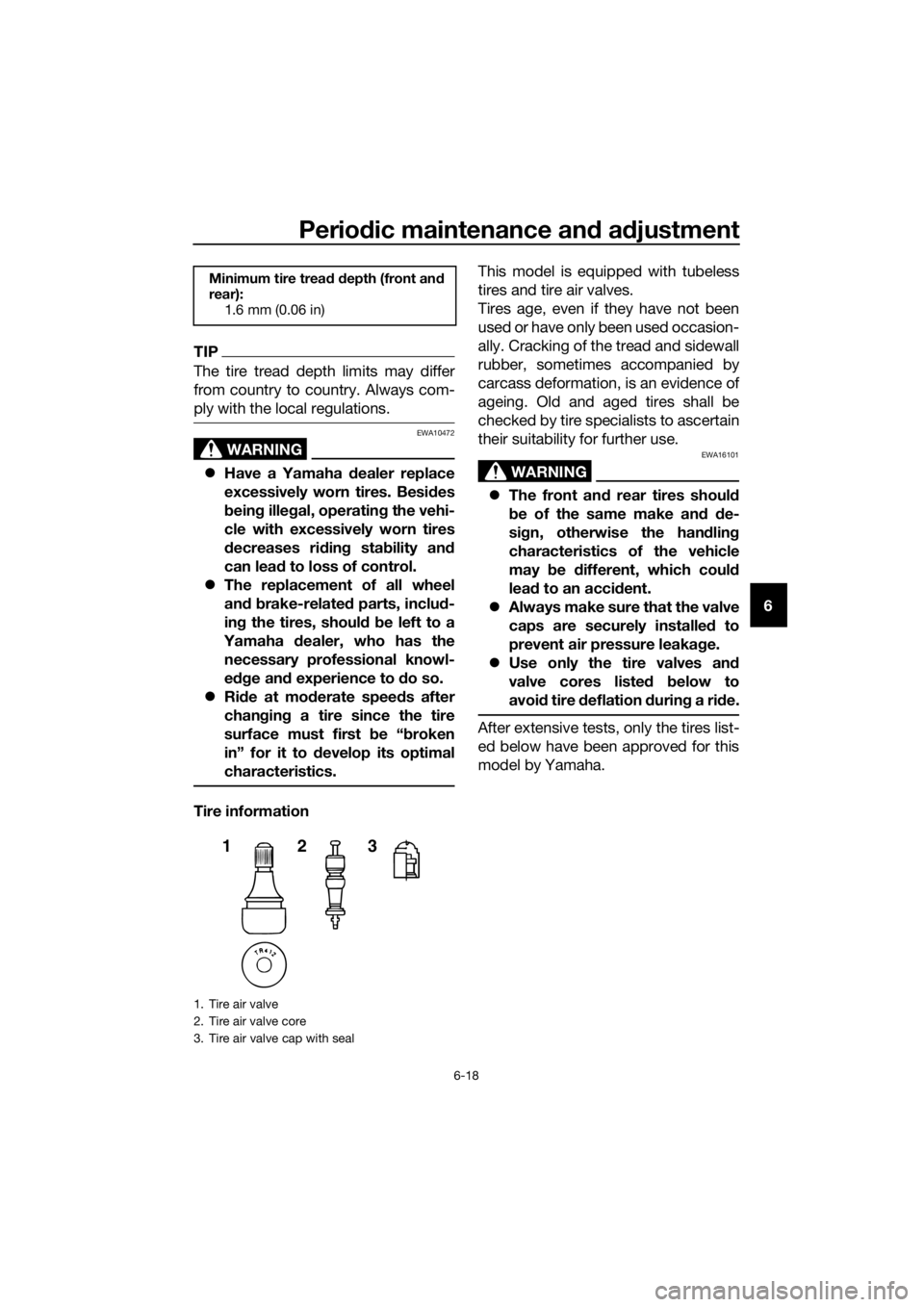
Always make sure that the valve
caps are securely installed to
prevent air pressure leakage.
Use only the tire valves and
valve cores listed below to
avoid tire deflation during a ride.
After extensive tests, only the tires list-
ed below have been approved for this
model by Yamaha.
Minimum tire tread depth (front and
rear):
1.6 mm (0.06 in)
1. Tire air valve
2. Tire air valve core
3. Tire air valve cap with seal
123
UB5GE0E0.book Page 18 Thursday, August 23, 2018 10:05 AM
Page 62 of 96

Periodic maintenance and adjustment
6-19
6
EAU21963
Cast wheels
To maximize the performance, durabil-
ity, and safe operation of your vehicle,
note the following points regarding the
specified wheels.
The wheel rims should be
checked for cracks, bends, warp-
age or other damage before each
ride. If any damage is found, have
a Yamaha dealer replace the
wheel. Do not attempt even the
smallest repair to the wheel. A de-
formed or cracked wheel must be
replaced.
The wheel should be balanced
whenever either the tire or wheel
has been changed or replaced. An
unbalanced wheel can result in
poor performance, adverse han-
dling characteristics, and a short-
ened tire life.
Front tire:
Size:
100/80-17M/C 52S
Manufacturer/model:
MICHELIN PILOT STREET
Tire air valve:
TR412
Valve core:
V3002 (original)
Rear tire:
Size:
140/70-17M/C 66S
Manufacturer/model:
MICHELIN PILOT STREET
Tire air valve:
TR412
Valve core:
V3002 (original)
UB5GE0E0.book Page 19 Thursday, August 23, 2018 10:05 AM
Page 68 of 96
Periodic maintenance and adjustment
6-25
6
EAU22762
Drive chain slack
The drive chain slack should be
checked before each ride and adjusted
if necessary.
EAU74253To check the drive chain slack
1. Place the motorcycle on the side-
stand.
TIP
When checking and adjusting the drive
chain slack, there should be no weight
on the motorcycle.
2. Shift the transmission into the
neutral position.
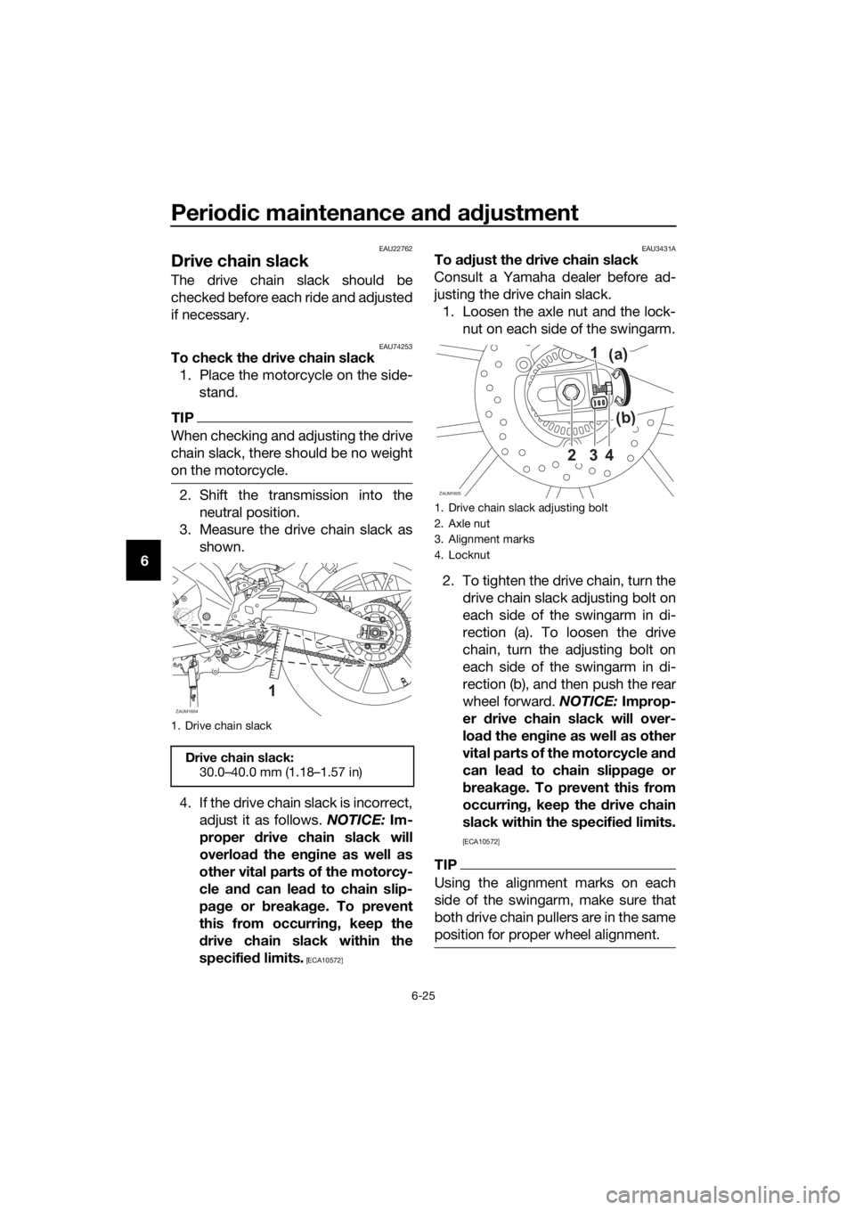
3. Measure the drive chain slack as
shown.
4. If the drive chain slack is incorrect,
adjust it as follows. NOTICE: Im-
proper drive chain slack will
overload the engine as well as
other vital parts of the motorcy-
cle and can lead to chain slip-
page or breakage. To prevent
this from occurring, keep the
drive chain slack within the
specified limits.
[ECA10572]EAU3431A
To adjust the drive chain slack
Consult a Yamaha dealer before ad-
justing the drive chain slack.
1. Loosen the axle nut and the lock-
nut on each side of the swingarm.
2. To tighten the drive chain, turn the
drive chain slack adjusting bolt on
each side of the swingarm in di-
rection (a). To loosen the drive
chain, turn the adjusting bolt on
each side of the swingarm in di-
rection (b), and then push the rear
wheel forward. NOTICE: Improp-
er drive chain slack will over-
load the engine as well as other
vital parts of the motorcycle and
can lead to chain slippage or
breakage. To prevent this from
occurring, keep the drive chain
slack within the specified limits.
[ECA10572]
TIP
Using the alignment marks on each
side of the swingarm, make sure that
both drive chain pullers are in the same
position for proper wheel alignment.
1. Drive chain slack
Drive chain slack:
30.0–40.0 mm (1.18–1.57 in)
ZAUM1604
1
1. Drive chain slack adjusting bolt
2. Axle nut
3. Alignment marks
4. Locknut
ZAUM1605
3 21
4
(b) (a)
UB5GE0E0.book Page 25 Thursday, August 23, 2018 10:05 AM
Page 73 of 96
Periodic maintenance and adjustment
6-30
6
EAU23273
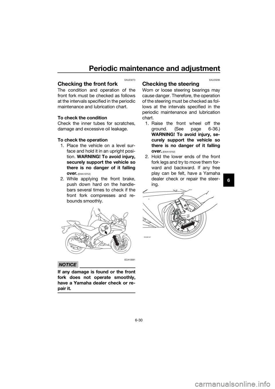
Checking the front fork
The condition and operation of the
front fork must be checked as follows
at the intervals specified in the periodic
maintenance and lubrication chart.
To check the condition
Check the inner tubes for scratches,
damage and excessive oil leakage.
To check the operation
1. Place the vehicle on a level sur-
face and hold it in an upright posi-
tion. WARNING! To avoid injury,
securely support the vehicle so
there is no danger of it falling
over.
[EWA10752]
2. While applying the front brake,
push down hard on the handle-
bars several times to check if the
front fork compresses and re-
bounds smoothly.
NOTICE
ECA10591
If any damage is found or the front
fork does not operate smoothly,
have a Yamaha dealer check or re-
pair it.
EAU23285
Checking the steering
Worn or loose steering bearings may
cause danger. Therefore, the operation
of the steering must be checked as fol-
lows at the intervals specified in the
periodic maintenance and lubrication
chart.
1. Raise the front wheel off the
ground. (See page 6-36.)
WARNING! To avoid injury, se-
curely support the vehicle so
there is no danger of it falling
over.
[EWA10752]
2. Hold the lower ends of the front
fork legs and try to move them for-
ward and backward. If any free
play can be felt, have a Yamaha
dealer check or repair the steer-
ing.
ZAUM1187
UB5GE0E0.book Page 30 Thursday, August 23, 2018 10:05 AM