light YAMAHA YZF-R125 2020 User Guide
[x] Cancel search | Manufacturer: YAMAHA, Model Year: 2020, Model line: YZF-R125, Model: YAMAHA YZF-R125 2020Pages: 96, PDF Size: 5.7 MB
Page 23 of 96
Instrument and control functions
3-9
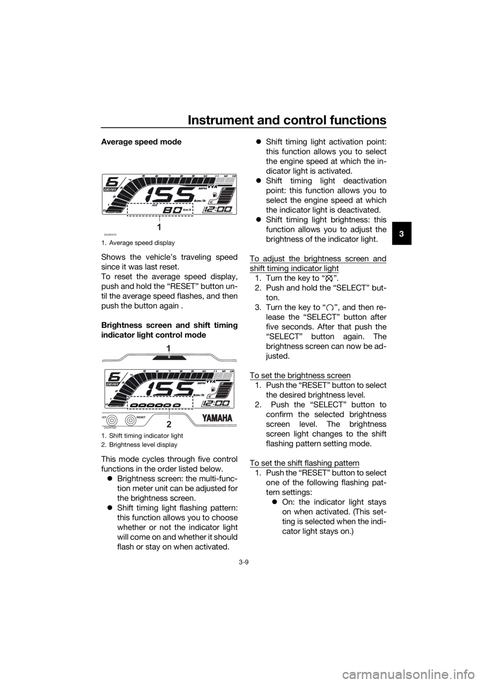
3 Average speed mode
Shows the vehicle’s traveling speed
since it was last reset.
To reset the average speed display,
push and hold the “RESET” button un-
til the average speed flashes, and then
push the button again .
Brightness screen and shift timing
indicator light control mode
This mode cycles through five control
functions in the order listed below.
Brightness screen: the multi-func-
tion meter unit can be adjusted for
the brightness screen.
Shift timing light flashing pattern:
this function allows you to choose
whether or not the indicator light
will come on and whether it should
flash or stay on when activated.Shift timing light activation point:
this function allows you to select
the engine speed at which the in-
dicator light is activated.
Shift timing light deactivation
point: this function allows you to
select the engine speed at which
the indicator light is deactivated.
Shift timing light brightness: this
function allows you to adjust the
brightness of the indicator light.
To adjust the brightness screen and
shift timing indicator light
1. Turn the key to “ ”.
2. Push and hold the “SELECT” but-
ton.
3. Turn the key to “ ”, and then re-
lease the “SELECT” button after
five seconds. After that push the
“SELECT” button again. The
brightness screen can now be ad-
justed.
To set the brightness screen
1. Push the “RESET” button to select
the desired brightness level.
2. Push the “SELECT” button to
confirm the selected brightness
screen level. The brightness
screen light changes to the shift
flashing pattern setting mode.
To set the shift flashing pattern
1. Push the “RESET” button to select
one of the following flashing pat-
tern settings:
On: the indicator light stays
on when activated. (This set-
ting is selected when the indi-
cator light stays on.)
1. Average speed display
1. Shift timing indicator light
2. Brightness level display
ZAUM15791
ZAUM15802
1
UB5GE1E0.book Page 9 Monday, August 26, 2019 3:02 PM
Page 24 of 96

Instrument and control functions
3-10
3Flash: the indicator light
flashes when activated. (This
setting is selected when the
indicator light flashes four
times per second.)
Off: the indicator light is deac-
tivated; in other words, it
does not come on or flash.
(This setting is selected when
the indicator light flashes
once every two seconds.)
2. Push the “SELECT” button to con-
firm the selected flashing pattern.
The shift timing indicator light
changes to the activation point
setting mode.
The tachometer will show the current
setting r/min for the activation point
and deactivation point setting modes.
To set the shift activation point
TIP
The shift timing indicator light activa-
tion point can be set between 9000
r/min and 13000 r/min. The indicator
light can be set in increments of 500
r/min.
1.
the desired engine speed for acti-
vating the indicator light.
2.
firm the selected engine speed.
The control mode changes to the
deactivation point setting mode.To set the shift deactivation point
TIP
The shift timing indicator light de-
activation point can be set be-
tween 9000 r/min and 13000
r/min. The indicator light can be
set in increments of 500 r/min.
Be sure to set the deactivation
point to a higher engine speed
than for the activation point, other-
wise the shift timing indicator light
will not come on.
1. Push the “RESET” button to select
the desired engine speed for de-
activating the indicator light.
2. Push the “SELECT” button to con-
firm the selected engine speed.
The control mode changes to the
brightness setting mode.
To adjust the shift brightness
1. Push the “RESET” button to select
the desired shift indicator light
brightness level.
2. Push the “SELECT” button to con-
firm the selected brightness level.
The display exits the shift timing
light control mode and returns to
the standard multi-function dis-
play mode.
Welcome screen
The welcome screen greets the rider
when the key is turned to “ ” with the
messages “Hi Buddy” and “see you”
when the key is turned to “ ”. The
user name “Buddy” is set as the facto-
ry default, but it can be set to your
name.
UB5GE1E0.book Page 10 Monday, August 26, 2019 3:02 PM
Page 25 of 96
Instrument and control functions
3-11
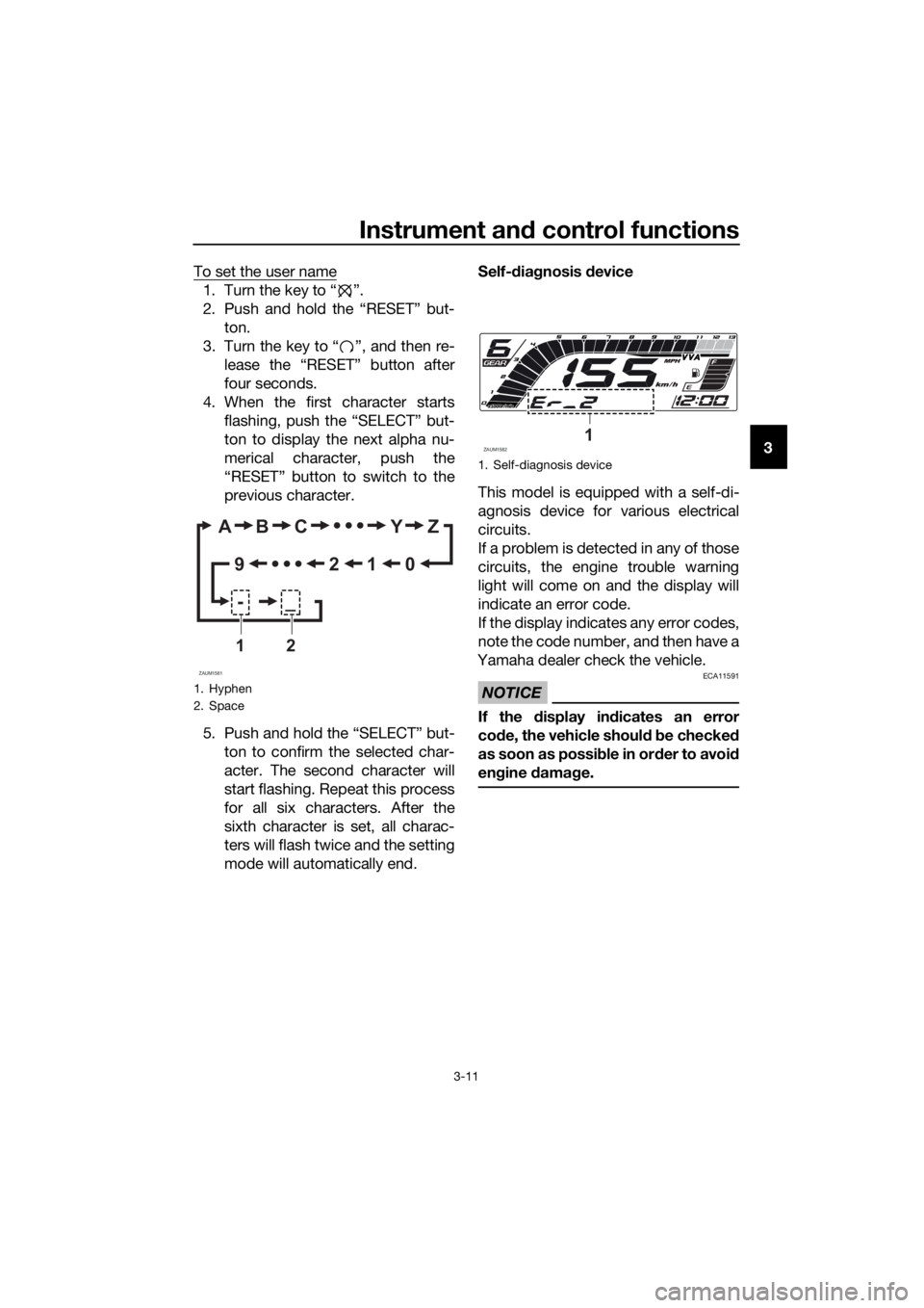
3 To set the user name
1. Turn the key to “ ”.
2. Push and hold the “RESET” but-
ton.
3. Turn the key to “ ”, and then re-
lease the “RESET” button after
four seconds.
4. When the first character starts
flashing, push the “SELECT” but-
ton to display the next alpha nu-
merical character, push the
“RESET” button to switch to the
previous character.
5. Push and hold the “SELECT” but-
ton to confirm the selected char-
acter. The second character will
start flashing. Repeat this process
for all six characters. After the
sixth character is set, all charac-
ters will flash twice and the setting
mode will automatically end.Self-diagnosis device
This model is equipped with a self-di-
agnosis device for various electrical
circuits.
If a problem is detected in any of those
circuits, the engine trouble warning
light will come on and the display will
indicate an error code.
If the display indicates any error codes,
note the code number, and then have a
Yamaha dealer check the vehicle.
NOTICE
ECA11591
If the display indicates an error
code, the vehicle should be checked
as soon as possible in order to avoid
engine damage.
1. Hyphen
2. Space
ZAUM1581
AB C Y Z
0 1 2 9
-_
12
1. Self-diagnosis device
ZAUM15821
UB5GE1E0.book Page 11 Monday, August 26, 2019 3:02 PM
Page 26 of 96
Instrument and control functions
3-12
3
EAU1234M
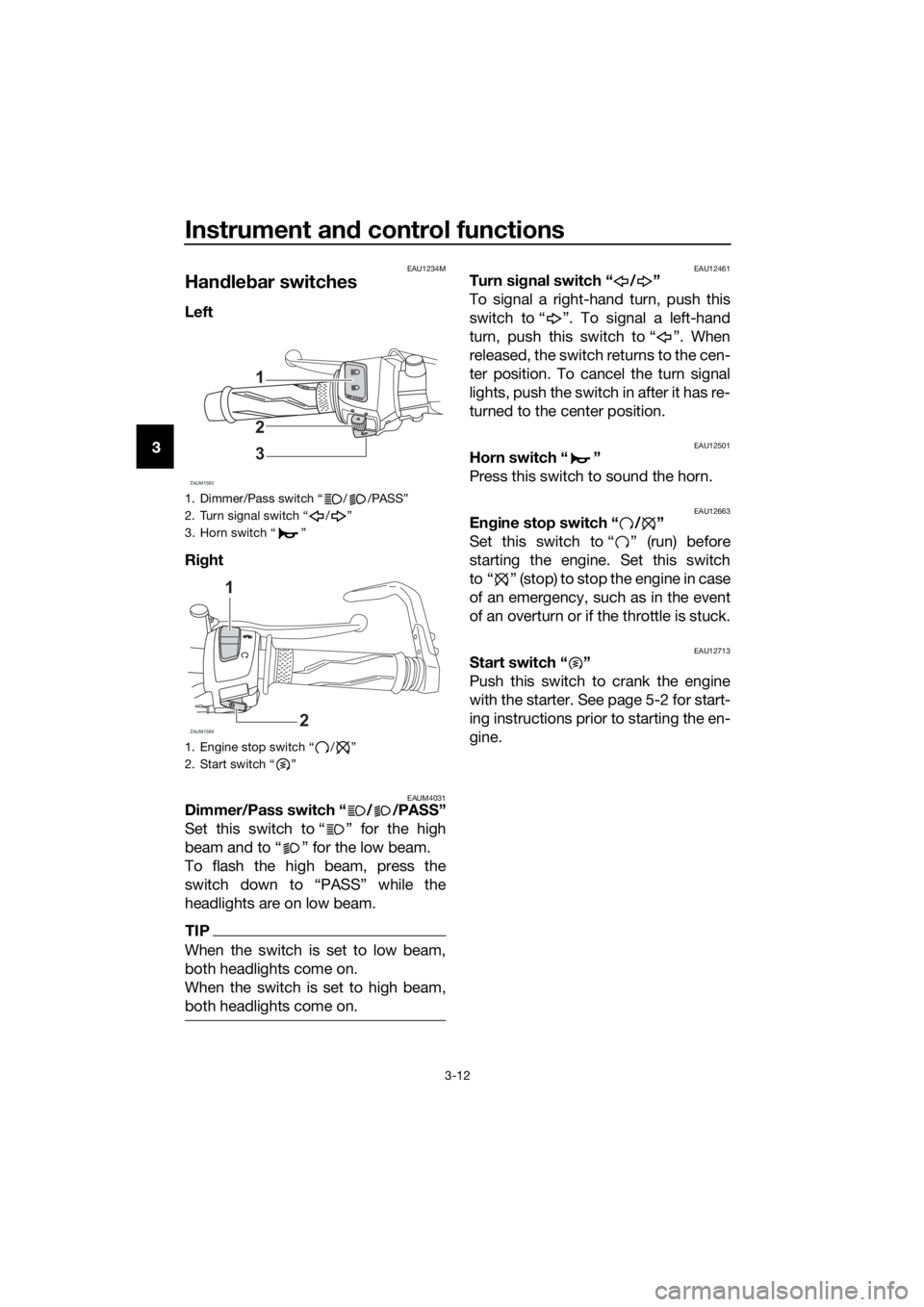
Handlebar switches
Left
Right
EAUM4031Dimmer/Pass switch “ / /PASS”
Set this switch to “ ” for the high
beam and to “ ” for the low beam.
To flash the high beam, press the
switch down to “PASS” while the
headlights are on low beam.
TIP
When the switch is set to low beam,
both headlights come on.
When the switch is set to high beam,
both headlights come on.
EAU12461Turn signal switch “ / ”
To signal a right-hand turn, push this
switch to “ ”. To signal a left-hand
turn, push this switch to “ ”. When
released, the switch returns to the cen-
ter position. To cancel the turn signal
lights, push the switch in after it has re-
turned to the center position.
EAU12501Horn switch “ ”
Press this switch to sound the horn.
EAU12663Engine stop switch “ / ”
Set this switch to “ ” (run) before
starting the engine. Set this switch
to “ ” (stop) to stop the engine in case
of an emergency, such as in the event
of an overturn or if the throttle is stuck.
EAU12713Start switch “ ”
Push this switch to crank the engine
with the starter. See page 5-2 for start-
ing instructions prior to starting the en-
gine.
1. Dimmer/Pass switch “ / /PASS”
2. Turn signal switch “ / ”
3. Horn switch “ ”
1. Engine stop switch “ / ”
2. Start switch “ ”
ZAUM1583
1
2
3
ZAUM1584
1
2
UB5GE1E0.book Page 12 Monday, August 26, 2019 3:02 PM
Page 29 of 96
Instrument and control functions
3-15
3
EAU63040
ABS
The Yamaha ABS (Anti-lock Brake
System) features a dual electronic con-
trol system, which acts on the front and
rear brakes independently.
Operate the brakes with ABS as you
would conventional brakes. If the ABS
is activated, a pulsating sensation may
be felt at the brake lever or brake ped-
al. In this situation, continue to apply
the brakes and let the ABS work; do
not “pump” the brakes as this will re-
duce braking effectiveness.
WARNING
EWA16051
Always keep a sufficient distance
from the vehicle ahead to match the
riding speed even with ABS.
The ABS performs best with
long braking distances.
On certain surfaces, such as
rough or gravel roads, the brak-
ing distance may be longer with
the ABS than without.
The ABS is monitored by an ECU,
which will revert the system to conven-
tional braking if a malfunction occurs.
TIP
The ABS performs a self-diagno-
sis test each time the vehicle first
starts off after the key is turned to
“ON” and the vehicle has traveled
at a speed of 10 km/h (6 mi/h) or
higher. During this test, a “click-
ing” noise can be heard from the
hydraulic control unit, and if the
brake lever or brake pedal is even
slightly applied, a vibration can be
felt at the lever and pedal, but
these do not indicate a malfunc-
tion.This ABS has a test mode which
allows the owner to experience
the pulsation at the brake lever or
brake pedal when the ABS is op-
erating. However, special tools are
required, so please consult your
Yamaha dealer.
NOTICE
ECA20100
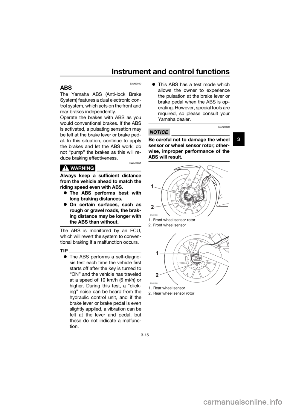
Be careful not to damage the wheel
sensor or wheel sensor rotor; other-
wise, improper performance of the
ABS will result.
1. Front wheel sensor rotor
2. Front wheel sensor
1. Rear wheel sensor
2. Rear wheel sensor rotor
ZAUM1589
1
2
ZAUM1590
1
2
UB5GE1E0.book Page 15 Monday, August 26, 2019 3:02 PM
Page 30 of 96

Instrument and control functions
3-16
3
EAU13077
Fuel tank cap
To open the fuel tank cap
Open the fuel tank cap lock cover, in-
sert the key, and then turn it 1/4 turn
clockwise. The lock will be released
and the fuel tank cap can be opened.
To close the fuel tank cap
With the key still inserted, push down
the fuel tank cap. Turn the key 1/4 turn
counterclockwise, remove it, and then
close the lock cover.
TIP
The fuel tank cap cannot be closed un-
less the key is in the lock. In addition,
the key cannot be removed if the cap is
not properly closed and locked.
WARNING
EWA11092
Make sure that the fuel tank cap is
properly closed after filling fuel.
Leaking fuel is a fire hazard.
EAU13213
Fuel
Make sure there is sufficient gasoline in
the tank.
WARNING
EWA10882
Gasoline and gasoline vapors are
extremely flammable. To avoid fires
and explosions and to reduce the
risk of injury when refueling, follow
these instructions.
1. Before refueling, turn off the en-
gine and be sure that no one is sit-
ting on the vehicle. Never refuel
while smoking, or while in the vi-
cinity of sparks, open flames, or
other sources of ignition such as
the pilot lights of water heaters
and clothes dryers.
2. Do not overfill the fuel tank. Stop
filling when the fuel reaches the
bottom of the filler tube. Because
fuel expands when it heats up,
heat from the engine or the sun
can cause fuel to spill out of the
fuel tank.
3. Wipe up any spilled fuel immedi-
ately. NOTICE: Immediately
wipe off spilled fuel with a clean,1. Fuel tank cap lock cover
2. Unlock.
ZAUM1591
2
1
1. Fuel tank filler tube
2. Maximum fuel level
UB5GE1E0.book Page 16 Monday, August 26, 2019 3:02 PM
Page 38 of 96

For your safety – pre-operation checks
4-2
4
Throttle grip• Make sure that operation is smooth.
• Check throttle grip free play.
• If necessary, have Yamaha dealer adjust throttle grip
free play and lubricate cable and grip housing.6-15,
6-27
Control cables• Make sure that operation is smooth.
• Lubricate if necessary.6-27
Drive chain• Check chain slack.
• Adjust if necessary.
• Check chain condition.
• Lubricate if necessary.6-25,
6-26
Wheels and tires•Check for damage.
• Check tire condition and tread depth.
• Check air pressure.
• Correct if necessary.6-17,
6-19
Brake and shift pedals• Make sure that operation is smooth.
• Lubricate pedal pivoting points if necessary.6-28
Brake and clutch le-
vers• Make sure that operation is smooth.
• Lubricate lever pivoting points if necessary.6-28
Sidestand• Make sure that operation is smooth.
• Lubricate pivot if necessary.6-29
Chassis fasteners• Make sure that all nuts, bolts and screws are properly
tightened.
• Tighten if necessary.—
Instruments, lights,
signals and switches• Check operation.
• Correct if necessary.—
Sidestand switch • Check operation of ignition circuit cut-off system.
• If system is not working correctly, have Yamaha dealer
check vehicle.3-20 ITEM CHECKS PAGE
UB5GE1E0.book Page 2 Monday, August 26, 2019 3:02 PM
Page 40 of 96
Operation and important riding points
5-2
51000 km (600 mi) and beyond
The vehicle can now be operated nor-
mally.
NOTICE
ECA10311
Keep the engine speed out of
the tachometer red zone.
If any engine trouble should oc-
cur during the engine break-in
period, immediately have a
Yamaha dealer check the vehi-
cle.
EAU86690
Starting the engine
The ignition circuit cut-off system will
enable starting when:
the transmission is in the neutral
position or
the transmission is in gear, the
sidestand is up, and the clutch le-
ver is pulled.
To start the engine
1. Turn the main switch on and set
the engine stop switch to the run
position.
2. Confirm the indicator and warning
light(s) come on for a few sec-
onds, and the go off. (See page
3-2.)
TIP
Do not start the engine if the en-
gine trouble warning light remains
on.
The ABS warning light should
come on and stay on until the ve-
hicle reaches a speed of 10 km/h
(6 mi/h).
NOTICE
ECA24110
If a warning or indicator light does
not work as described above, have a
Yamaha dealer check the vehicle.
3. Shift the transmission into the
neutral position.
4. Start the engine by pushing the
start switch.
5. Release the start switch when the
engine starts, or after 5 seconds.
Wait 10 seconds before pressing
the switch again to allow battery
voltage to restore.
UB5GE1E0.book Page 2 Monday, August 26, 2019 3:02 PM
Page 42 of 96
Operation and important riding points
5-4
5
EAU16674
Shifting
Shifting gears lets you control the
amount of engine power available for
starting off, accelerating, climbing hills,
etc.
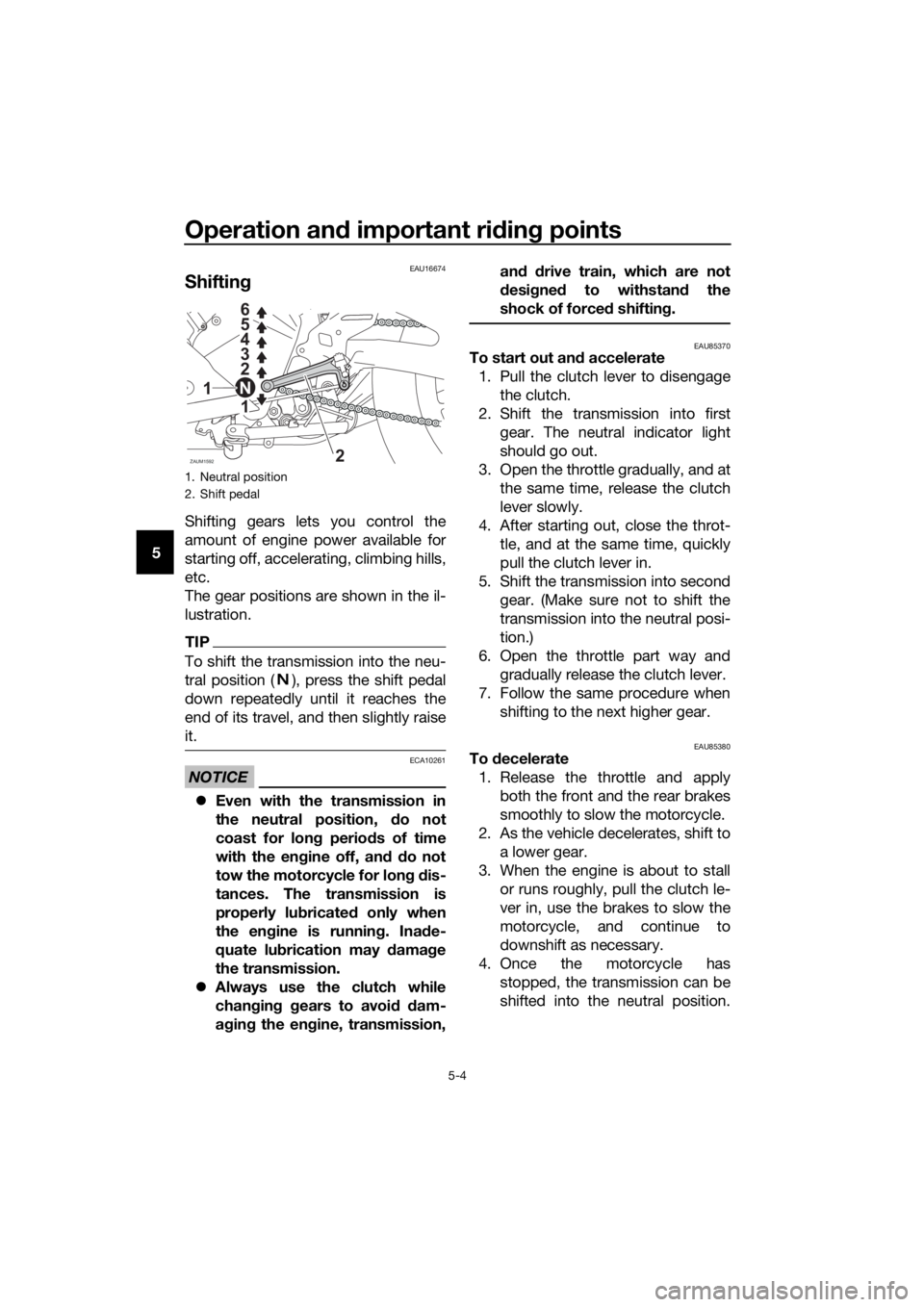
The gear positions are shown in the il-
lustration.
TIP
To shift the transmission into the neu-
tral position ( ), press the shift pedal
down repeatedly until it reaches the
end of its travel, and then slightly raise
it.
NOTICE
ECA10261
Even with the transmission in
the neutral position, do not
coast for long periods of time
with the engine off, and do not
tow the motorcycle for long dis-
tances. The transmission is
properly lubricated only when
the engine is running. Inade-
quate lubrication may damage
the transmission.
Always use the clutch while
changing gears to avoid dam-
aging the engine, transmission,and drive train, which are not
designed to withstand the
shock of forced shifting.
EAU85370To start out and accelerate
1. Pull the clutch lever to disengage
the clutch.
2. Shift the transmission into first
gear. The neutral indicator light
should go out.
3. Open the throttle gradually, and at
the same time, release the clutch
lever slowly.
4. After starting out, close the throt-
tle, and at the same time, quickly
pull the clutch lever in.
5. Shift the transmission into second
gear. (Make sure not to shift the
transmission into the neutral posi-
tion.)
6. Open the throttle part way and
gradually release the clutch lever.
7. Follow the same procedure when
shifting to the next higher gear.
EAU85380To decelerate
1. Release the throttle and apply
both the front and the rear brakes
smoothly to slow the motorcycle.
2. As the vehicle decelerates, shift to
a lower gear.
3. When the engine is about to stall
or runs roughly, pull the clutch le-
ver in, use the brakes to slow the
motorcycle, and continue to
downshift as necessary.
4. Once the motorcycle has
stopped, the transmission can be
shifted into the neutral position.
1. Neutral position
2. Shift pedal
ZAUM1592
1 2 3 4 5
6
1
2 N
UB5GE1E0.book Page 4 Monday, August 26, 2019 3:02 PM
Page 43 of 96

Operation and important riding points
5-5
5 The neutral indicator light should
come on and then the clutch lever
can be released.
WARNING
EWA17380
Improper braking can cause
loss of control or traction. Al-
ways use both brakes and apply
them smoothly.
Make sure that the motorcycle
and the engine have sufficiently
slowed before shifting to a low-
er gear. Engaging a lower gear
when the vehicle or engine
speed is too high could make
the rear wheel lose traction or
the engine to over-rev. This
could cause loss of control, an
accident and injury. It could also
cause engine or drive train dam-
age.
EAU16811
Tips for reducing fuel con-
sumption
Fuel consumption depends largely on
your riding style. Consider the follow-
ing tips to reduce fuel consumption:
Shift up swiftly, and avoid high en-
gine speeds during acceleration.
Do not rev the engine while shift-
ing down, and avoid high engine
speeds with no load on the en-
gine.
Turn the engine off instead of let-
ting it idle for an extended length
of time (e.g., in traffic jams, at traf-
fic lights or at railroad crossings).
UB5GE1E0.book Page 5 Monday, August 26, 2019 3:02 PM