check engine YAMAHA YZF-R125 2020 Owner's Manual
[x] Cancel search | Manufacturer: YAMAHA, Model Year: 2020, Model line: YZF-R125, Model: YAMAHA YZF-R125 2020Pages: 96, PDF Size: 5.7 MB
Page 60 of 96

Periodic maintenance and adjustment
6-16
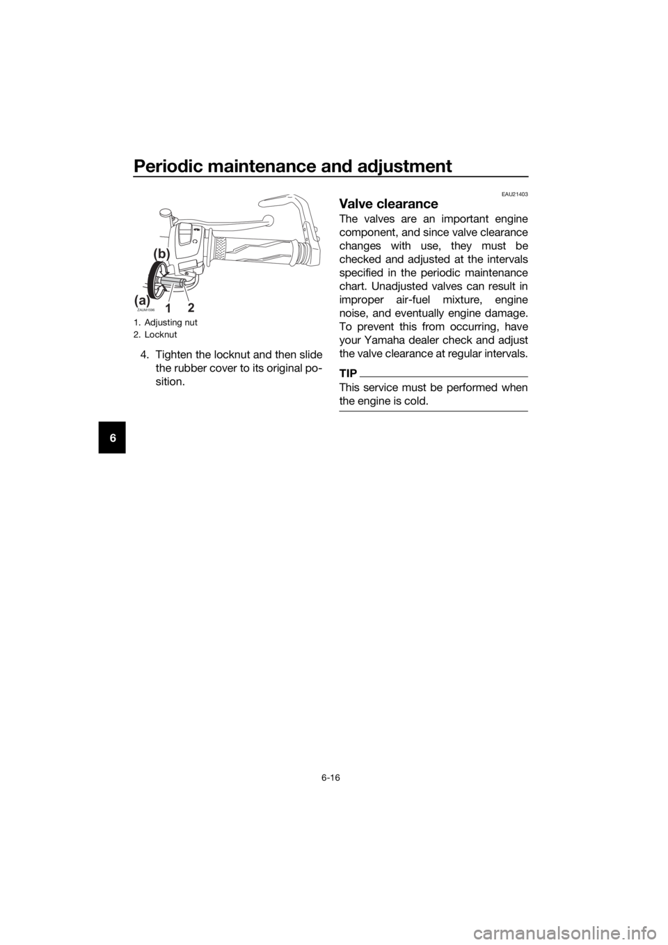
64. Tighten the locknut and then slide
the rubber cover to its original po-
sition.
EAU21403
Valve clearance
The valves are an important engine
component, and since valve clearance
changes with use, they must be
checked and adjusted at the intervals
specified in the periodic maintenance
chart. Unadjusted valves can result in
improper air-fuel mixture, engine
noise, and eventually engine damage.
To prevent this from occurring, have
your Yamaha dealer check and adjust
the valve clearance at regular intervals.
TIP
This service must be performed when
the engine is cold.
1. Adjusting nut
2. Locknut
ZAUM159612(a)
(b)
UB5GE1E0.book Page 16 Monday, August 26, 2019 3:02 PM
Page 69 of 96

Periodic maintenance and adjustment
6-25
6
EAU22762
Drive chain slack
The drive chain slack should be
checked before each ride and adjusted
if necessary.
EAU74253To check the drive chain slack
1. Place the motorcycle on the side-
stand.
TIP
When checking and adjusting the drive
chain slack, there should be no weight
on the motorcycle.
2. Shift the transmission into the
neutral position.
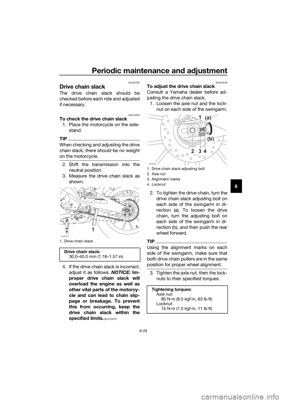
3. Measure the drive chain slack as
shown.
4. If the drive chain slack is incorrect,
adjust it as follows. NOTICE: Im-
proper drive chain slack will
overload the engine as well as
other vital parts of the motorcy-
cle and can lead to chain slip-
page or breakage. To prevent
this from occurring, keep the
drive chain slack within the
specified limits.
[ECA10572]EAU3431B
To adjust the drive chain slack
Consult a Yamaha dealer before ad-
justing the drive chain slack.
1. Loosen the axle nut and the lock-
nut on each side of the swingarm.
2. To tighten the drive chain, turn the
drive chain slack adjusting bolt on
each side of the swingarm in di-
rection (a). To loosen the drive
chain, turn the adjusting bolt on
each side of the swingarm in di-
rection (b), and then push the rear
wheel forward.
TIP
Using the alignment marks on each
side of the swingarm, make sure that
both drive chain pullers are in the same
position for proper wheel alignment.
3. Tighten the axle nut, then the lock-
nuts to their specified torques.
1. Drive chain slack
Drive chain slack:
30.0–40.0 mm (1.18–1.57 in)
ZAUM1604
1
1. Drive chain slack adjusting bolt
2. Axle nut
3. Alignment marks
4. Locknut
Tightening torques:
Axle nut:
85 N·m (8.5 kgf·m, 63 lb·ft)
Locknut:
15 N·m (1.5 kgf·m, 11 lb·ft)
ZAUM1605
3 21
4
(b) (a)
UB5GE1E0.book Page 25 Monday, August 26, 2019 3:02 PM
Page 81 of 96

Periodic maintenance and adjustment
6-37
6
EAU86390
Troubleshooting chart
1. FuelThere is enough fuel.
There is no fuel.
Check the battery.
Supply fuel.
The engine turns over
quickly.
The engine turns over
slowly.
Try starting the
engine.
The engine does not
start.
Check the battery.
Wipe off with a dry
cloth and correct the
spark plug gap, or
replace the spark
plug(s).
Check the battery
lead connections,
and charge the
battery if necessary.
2. BatteryThe battery is good.
The engine does not
start.
Check the ignition.
3. IgnitionWet
Dry
There is compression.
There is no
compression.
The engine does not start.
Have a Yamaha dealer check the vehicle.
Have a Yamaha dealer check the vehicle.
The engine does not
start.
Check the
compression.Have a Yamaha
dealer check the
vehicle.
Remove the spark
plug and check
the electrodes.
Operate the electric
starter.
Try starting the
engine.
Check the fuel level
in the fuel tank.
4. Compression
UB5GE1E0.book Page 37 Monday, August 26, 2019 3:02 PM
Page 82 of 96

Periodic maintenance and adjustment
6-38
6
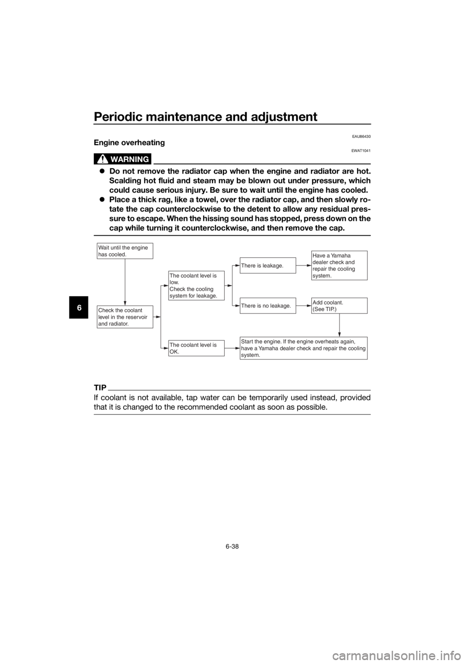
EAU86430Engine overheating
WARNING
EWAT1041
Do not remove the radiator cap when the engine and radiator are hot.
Scalding hot fluid and steam may be blown out under pressure, which
could cause serious injury. Be sure to wait until the engine has cooled.
Place a thick rag, like a towel, over the radiator cap, and then slowly ro-
tate the cap counterclockwise to the detent to allow any residual pres-
sure to escape. When the hissing sound has stopped, press down on the
cap while turning it counterclockwise, and then remove the cap.
TIP
If coolant is not available, tap water can be temporarily used instead, provided
that it is changed to the recommended coolant as soon as possible.
Wait until the engine
has cooled.
Check the coolant
level in the reservoir
and radiator.Add coolant.
(See TIP.)
The coolant level is
OK.
There is no leakage.
There is leakage.
The coolant level is
low.
Check the cooling
system for leakage.
Have a Yamaha
dealer check and
repair the cooling
system.
Start the engine. If the engine overheats again,
have a Yamaha dealer check and repair the cooling
system.
UB5GE1E0.book Page 38 Monday, August 26, 2019 3:02 PM
Page 92 of 96

Consumer information
9-3
9
EAU85300
Vehicle data recording
This model’s ECU stores certain vehi-
cle data to assist in the diagnosis of
malfunctions and for research, statisti-
cal analysis and development purpos-
es.
Although the sensors and recorded
data will vary by model, the main data
points are:
Vehicle status and engine perfor-
mance data
Fuel-injection and emission-relat-
ed data
This data will be uploaded only when a
special Yamaha diagnostic tool is at-
tached to the vehicle, such as when
maintenance checks or service proce-
dures are performed.
Vehicle data uploaded will be handled
appropriately according to the follow-
ing Privacy Policy.
Privacy Policy
Yamaha will not disclose this data to a
third party except in the following cas-
es. In addition, Yamaha may provide
vehicle data to a contractor in order to
outsource services related to the han-
dling of vehicle data. Even in this case,
Yamaha will require the contractor to
properly handle the vehicle data we
provided and Yamaha will appropriate-
ly manage the data.
With the consent of the vehicle
owner
Where obligated by law
For use by Yamaha in litigation
When the data is not related to an
individual vehicle nor owner
https://www.yamaha-motor.eu/eu/
privacy/privacy-policy.aspx
UB5GE1E0.book Page 3 Monday, August 26, 2019 3:02 PM
Page 93 of 96

10-1
10
Index
A
ABS ...................................................... 3-15
ABS warning light ................................... 3-3
Air filter element and check hose,
replacing and cleaning ....................... 6-14
B
Battery .................................................. 6-31
Brake and clutch levers, checking and
lubricating .......................................... 6-28
Brake and shift pedals, checking and
lubricating .......................................... 6-28
Brake fluid, changing ........................... 6-24
Brake fluid level, checking ................... 6-23
Brake lever ........................................... 3-14
Brake light switches ............................. 6-22
Brake pedal .......................................... 3-14
Brake pedal free play, adjusting........... 6-21
C
Cables, checking and lubricating ......... 6-27
Care ........................................................ 7-1
Catalytic converter ............................... 3-18
Clutch lever .......................................... 3-13
Clutch lever free play, adjusting ........... 6-20
Coolant ................................................. 6-13
Coolant temperature warning light ......... 3-2
Cowlings, removing and installing ......... 6-7
D
Data recording, vehicle .......................... 9-3
Diagnostic connectors ........................... 9-2
Dimmer/Pass switch ............................ 3-12
Drive chain, cleaning and lubricating ... 6-26
Drive chain slack .................................. 6-25
E
Engine break-in ...................................... 5-1
Engine idling speed .............................. 6-15
Engine oil and oil filter element ............ 6-10
Engine overheating............................... 6-38
Engine serial number.............................. 9-1
Engine stop switch ............................... 3-12
Engine trouble warning light................... 3-3
F
Front and rear brake pads, checking ... 6-22
Front brake lever free play, checking ... 6-21
Front fork, checking ............................. 6-30
Fuel....................................................... 3-16
Fuel consumption, tips for reducing ...... 5-5
Fuel tank cap........................................ 3-16
Fuel tank overflow hose ....................... 3-18
Fuses, replacing ................................... 6-33
H
Handlebar switches .............................. 3-12
High beam indicator light........................ 3-2
Horn switch........................................... 3-12
I
Identification numbers ............................ 9-1
Ignition circuit cut-off system ............... 3-21
Indicator lights and warning lights .......... 3-2
L
License plate light bulb, replacing ........ 6-35
M
Main switch/steering lock ....................... 3-1
Maintenance and lubrication, periodic ... 6-4
Maintenance, emission control
system .................................................. 6-3
Matte color, caution ................................ 7-1
Model label ............................................. 9-1
Multi-function meter unit ........................ 3-4
N
Neutral indicator light.............................. 3-2
P
Parking .................................................... 5-6
Part locations .......................................... 2-1
S
Safety information................................... 1-1
Seats ..................................................... 3-19
Shifting .................................................... 5-4
Shift light ................................................. 3-3
Shift pedal............................................. 3-13
Sidestand .............................................. 3-20
Sidestand, checking and lubricating .... 6-29
Spark plug, checking .............................. 6-9
Specifications ......................................... 8-1
Starting the engine.................................. 5-2
Start switch ........................................... 3-12
Steering, checking ................................ 6-30
Storage ................................................... 7-4
Supporting the motorcycle ................... 6-36
Swingarm pivots, lubricating ................ 6-29
T
Tail/brake light ...................................... 6-34
Throttle grip and cable, checking and
lubricating ........................................... 6-27
Throttle grip free play, adjusting ........... 6-15
Tires ...................................................... 6-17
Tool kit .................................................... 6-2
Troubleshooting .................................... 6-36
Troubleshooting chart........................... 6-37
Turn signal indicator light ....................... 3-2
Turn signal light bulb, replacing............ 6-35
UB5GE1E0.book Page 1 Monday, August 26, 2019 3:02 PM