spark YAMAHA YZF-R125 2020 Owners Manual
[x] Cancel search | Manufacturer: YAMAHA, Model Year: 2020, Model line: YZF-R125, Model: YAMAHA YZF-R125 2020Pages: 96, PDF Size: 5.7 MB
Page 5 of 96

Table of contents
Safety information............................1-1
Description........................................2-1
Left view ..........................................2-1
Right view........................................2-2
Controls and instruments ................2-3
Instrument and control functions....3-1
Main switch/steering lock ...............3-1
Indicator lights and warning
lights ............................................3-2
Multi-function meter unit .................3-4
Handlebar switches.......................3-12
Clutch lever ...................................3-13
Shift pedal .....................................3-13
Brake lever ....................................3-14
Brake pedal ...................................3-14
ABS ...............................................3-15
Fuel tank cap.................................3-16
Fuel................................................3-16
Fuel tank overflow hose ................3-18
Catalytic converter ........................3-18
Seats .............................................3-19
Sidestand ......................................3-20
Ignition circuit cut-off system........3-21
For your safety – pre-operation
checks...............................................4-1
Operation and important riding
points.................................................5-1
Engine break-in ...............................5-1
Starting the engine ..........................5-2
Shifting ............................................5-4
Tips for reducing fuel
consumption ................................5-5
Parking ............................................5-6
Periodic maintenance and
adjustment........................................6-1
Tool kit.............................................6-2
Periodic maintenance chart for the
emission control system ..............6-3
General maintenance and
lubrication chart ...........................6-4
Removing and installing cowlings ...6-7Checking the spark plug ................. 6-9
Engine oil and oil filter element ..... 6-10
Why Yamalube .............................. 6-12
Coolant ......................................... 6-13
Replacing the air filter element
and cleaning the check hose..... 6-14
Adjusting the engine idling
speed......................................... 6-15
Adjusting the throttle grip free
play ............................................ 6-15
Valve clearance ............................. 6-16
Tires .............................................. 6-17
Cast wheels .................................. 6-19
Adjusting the clutch lever free
play ............................................ 6-20
Checking the front brake lever
free play ..................................... 6-21
Adjusting the brake pedal free
play ............................................ 6-21
Brake light switches ...................... 6-22
Checking the front and rear brake
pads........................................... 6-22
Checking the brake fluid level....... 6-23
Changing the brake fluid............... 6-24
Drive chain slack ........................... 6-25
Cleaning and lubricating the drive
chain .......................................... 6-26
Checking and lubricating the
cables ........................................ 6-27
Checking and lubricating the
throttle grip and cable ............... 6-27
Checking and lubricating the
brake and shift pedals ............... 6-28
Checking and lubricating the
brake and clutch levers ............. 6-28
Checking and lubricating the
sidestand ................................... 6-29
Lubricating the swingarm pivots... 6-29
Checking the front fork ................. 6-30
Checking the steering ................... 6-30
Checking the wheel bearings ....... 6-31
Battery .......................................... 6-31
Replacing the fuses ...................... 6-33
Vehicle lights ................................. 6-34
Tail/brake light .............................. 6-34
UB5GE1E0.book Page 1 Monday, August 26, 2019 3:02 PM
Page 30 of 96

Instrument and control functions
3-16
3
EAU13077
Fuel tank cap
To open the fuel tank cap
Open the fuel tank cap lock cover, in-
sert the key, and then turn it 1/4 turn
clockwise. The lock will be released
and the fuel tank cap can be opened.
To close the fuel tank cap
With the key still inserted, push down
the fuel tank cap. Turn the key 1/4 turn
counterclockwise, remove it, and then
close the lock cover.
TIP
The fuel tank cap cannot be closed un-
less the key is in the lock. In addition,
the key cannot be removed if the cap is
not properly closed and locked.
WARNING
EWA11092
Make sure that the fuel tank cap is
properly closed after filling fuel.
Leaking fuel is a fire hazard.
EAU13213
Fuel
Make sure there is sufficient gasoline in
the tank.
WARNING
EWA10882
Gasoline and gasoline vapors are
extremely flammable. To avoid fires
and explosions and to reduce the
risk of injury when refueling, follow
these instructions.
1. Before refueling, turn off the en-
gine and be sure that no one is sit-
ting on the vehicle. Never refuel
while smoking, or while in the vi-
cinity of sparks, open flames, or
other sources of ignition such as
the pilot lights of water heaters
and clothes dryers.
2. Do not overfill the fuel tank. Stop
filling when the fuel reaches the
bottom of the filler tube. Because
fuel expands when it heats up,
heat from the engine or the sun
can cause fuel to spill out of the
fuel tank.
3. Wipe up any spilled fuel immedi-
ately. NOTICE: Immediately
wipe off spilled fuel with a clean,1. Fuel tank cap lock cover
2. Unlock.
ZAUM1591
2
1
1. Fuel tank filler tube
2. Maximum fuel level
UB5GE1E0.book Page 16 Monday, August 26, 2019 3:02 PM
Page 47 of 96

Periodic maintenance and adjustment
6-3
6
EAU71021
TIP
The annual checks must be performed every year, except if a distance-
based maintenance is performed instead.
From 30000 km (17500 mi), repeat the maintenance intervals starting from
6000 km (3500 mi).
Items marked with an asterisk should be performed by a Yamaha dealer as
they require special tools, data and technical skills.
EAU71060
Periodic maintenance chart for the emission control system
NO. ITEM
1*Fuel line• Check fuel hoses for cracks or
damage.
• Replace if necessary.√√√√√
2*Spark plug• Check condition.
• Adjust gap and clean.√√
• Replace.√√
3*Valve clearance• Check and adjust.√√√√
4*Fuel injection• Check and adjust engine idle
speed.√√√√√√
5*Exhaust system• Check for leakage.
• Tighten if necessary.
• Replace gasket if necessary.√√√√√X 1000 km CHECK OR
MAINTENANCE JOB
X 1000 mi
ODOMETER
READING
ANNUAL CHECK
16121824
0.63.5710.514
UB5GE1E0.book Page 3 Monday, August 26, 2019 3:02 PM
Page 53 of 96

Periodic maintenance and adjustment
6-9
6
EAU19623
Checking the spark plug
The spark plug is an important engine
component, which should be checked
periodically, preferably by a Yamaha
dealer. Since heat and deposits will
cause any spark plug to slowly erode,
it should be removed and checked in
accordance with the periodic mainte-
nance and lubrication chart. In addi-
tion, the condition of the spark plug
can reveal the condition of the engine.
The porcelain insulator around the
center electrode of the spark plug
should be a medium-to-light tan (the
ideal color when the vehicle is ridden
normally). If the spark plug shows a
distinctly different color, the engine
could be operating improperly. Do not
attempt to diagnose such problems
yourself. Instead, have a Yamaha deal-
er check the vehicle.
If the spark plug shows signs of elec-
trode erosion and excessive carbon or
other deposits, it should be replaced.
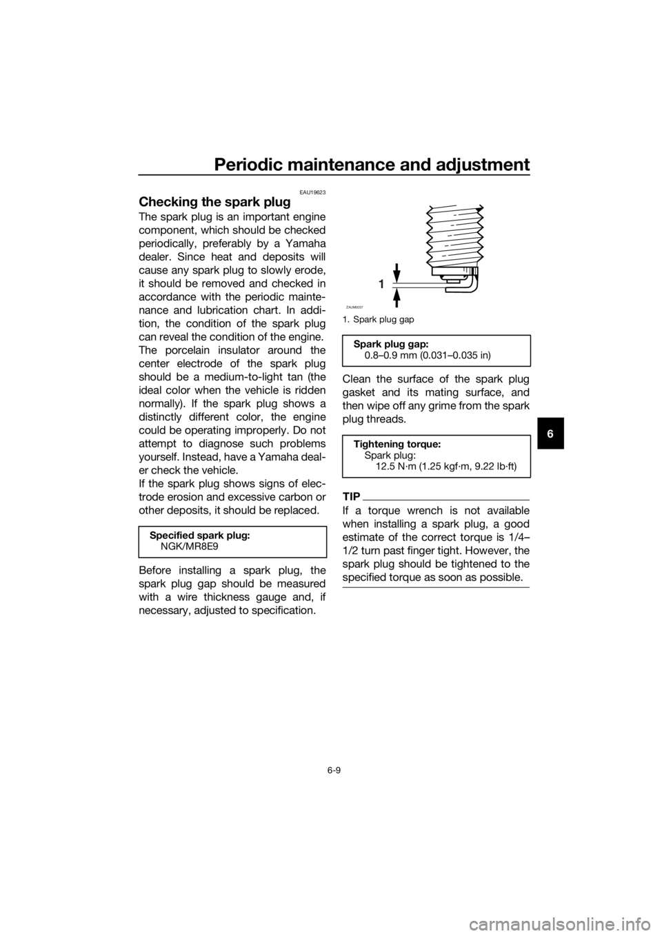
Before installing a spark plug, the
spark plug gap should be measured
with a wire thickness gauge and, if
necessary, adjusted to specification.Clean the surface of the spark plug
gasket and its mating surface, and
then wipe off any grime from the spark
plug threads.
TIP
If a torque wrench is not available
when installing a spark plug, a good
estimate of the correct torque is 1/4…
1/2 turn past finger tight. However, the
spark plug should be tightened to the
specified torque as soon as possible.
Specified spark plug:
NGK/MR8E9
1. Spark plug gap
Spark plug gap:
0.8–0.9 mm (0.031–0.035 in)
Tightening torque:
Spark plug:
12.5 N·m (1.25 kgf·m, 9.22 lb·ft)
1
ZAUM0037
UB5GE1E0.book Page 9 Monday, August 26, 2019 3:02 PM
Page 76 of 96

Periodic maintenance and adjustment
6-32
6Batteries produce explosive hy-
drogen gas. Therefore, keep
sparks, flames, cigarettes, etc.,
away from the battery and pro-
vide sufficient ventilation when
charging it in an enclosed
space.
KEEP THIS AND ALL BATTER-
IES OUT OF THE REACH OF
CHILDREN.
NOTICE
ECA10621
Never attempt to remove the battery
cell seals, as this would permanently
damage the battery.
To charge the battery
Have your Yamaha dealer charge the
battery if it seems to have discharged.
Keep in mind that the battery tends to
discharge more quickly if the vehicle is
equipped with optional electrical ac-
cessories.
NOTICE
ECA16522
To charge a VRLA (Valve Regulated
Lead Acid) battery, a special (con-
stant-voltage) battery charger is re-
quired. Using a conventional battery
charger will damage the battery.
To store the battery
1. If the vehicle will not be used for
more than one month, remove the
battery, fully charge it, and then
place it in a cool, dry place.
NOTICE: When removing the
battery, be sure to turn the main
switch off, then disconnect the
negative lead before discon-
necting the positive lead.
[ECA16304]
2. If the battery will be stored for
more than two months, check it at
least once a month and fully
charge it if necessary.
3. Fully charge the battery before in-
stallation. NOTICE: When install-
ing the battery, be sure to turn
the main switch off, then con-
nect the positive lead before
connecting the negative lead.
[ECA16842]
4. After installation, make sure that
the battery leads are properly con-
nected to the battery terminals.
NOTICE
ECA16531
Always keep the battery charged.
Storing a discharged battery can
cause permanent battery damage.
UB5GE1E0.book Page 32 Monday, August 26, 2019 3:02 PM
Page 80 of 96

Periodic maintenance and adjustment
6-36
6
EAU67131
Supporting the motorcycle
Since this model is not equipped with a
centerstand, use maintenance stands
when removing the front or rear wheel
or when performing other maintenance
that requires the motorcycle to stand
up right.
Check that the motorcycle is in a stable
and level position before starting any
maintenance.
EAU25872
Troubleshooting
Although Yamaha motorcycles receive
a thorough inspection before shipment
from the factory, trouble may occur
during operation. Any problem in the
fuel, compression, or ignition systems,
for example, can cause poor starting
and loss of power.
The following troubleshooting charts
represent quick and easy procedures
for checking these vital systems your-
self. However, should your motorcycle
require any repair, take it to a Yamaha
dealer, whose skilled technicians have
the necessary tools, experience, and
know-how to service the motorcycle
properly.
Use only genuine Yamaha replace-
ment parts. Imitation parts may look
like Yamaha parts, but they are often
inferior, have a shorter service life and
can lead to expensive repair bills.
WARNING
EWA15142
When checking the fuel system, do
not smoke, and make sure there are
no open flames or sparks in the ar-
ea, including pilot lights from water
heaters or furnaces. Gasoline or
gasoline vapors can ignite or ex-
plode, causing severe injury or prop-
erty damage.
1. Maintenance stand (example)
1
UB5GE1E0.book Page 36 Monday, August 26, 2019 3:02 PM
Page 81 of 96

Periodic maintenance and adjustment
6-37
6
EAU86390
Troubleshooting chart
1. FuelThere is enough fuel.
There is no fuel.
Check the battery.
Supply fuel.
The engine turns over
quickly.
The engine turns over
slowly.
Try starting the
engine.
The engine does not
start.
Check the battery.
Wipe off with a dry
cloth and correct the
spark plug gap, or
replace the spark
plug(s).
Check the battery
lead connections,
and charge the
battery if necessary.
2. BatteryThe battery is good.
The engine does not
start.
Check the ignition.
3. IgnitionWet
Dry
There is compression.
There is no
compression.
The engine does not start.
Have a Yamaha dealer check the vehicle.
Have a Yamaha dealer check the vehicle.
The engine does not
start.
Check the
compression.Have a Yamaha
dealer check the
vehicle.
Remove the spark
plug and check
the electrodes.
Operate the electric
starter.
Try starting the
engine.
Check the fuel level
in the fuel tank.
4. Compression
UB5GE1E0.book Page 37 Monday, August 26, 2019 3:02 PM
Page 86 of 96

Motorcycle care and storage
7-4
7
EAU83472
Storage
Always store the vehicle in a cool, dry
place. If necessary, protect it against
dust with a porous cover. Be sure the
engine and the exhaust system are
cool before covering the vehicle. If the
vehicle often sits for weeks at a time
between uses, the use of a quality fuel
stabilizer is recommended after each
fill-up.
NOTICE
ECA21170
Storing the vehicle in a poorly
ventilated room or covering it
with a tarp, while it is still wet,
will allow water and humidity to
seep in and cause rust.
To prevent corrosion, avoid
damp cellars, stables (because
of the presence of ammonia)
and areas where strong chemi-
cals are stored.
Long term storage
Before storing the vehicle long term (60
days or more):
1. Make all necessary repairs and
perform any outstanding mainte-
nance.
2. Follow all instructions in the Care
section of this chapter.
3. Fill up the fuel tank, adding fuel
stabilizer according to product in-
structions. Run the engine for 5
minutes to distribute treated fuel
through the fuel system.
4. For vehicles equipped with a fuel
cock: Turn the fuel cock lever to
the off position.5. For vehicles with a carburetor: To
prevent fuel deposits from build-
ing up, drain the fuel in the carbu-
retor float chamber into a clean
container. Retighten the drain bolt
and pour the fuel back into the fuel
tank.
6. Use a quality engine fogging oil
according to product instructions
to protect internal engine compo-
nents from corrosion. If engine
fogging oil is not available, per-
form the following steps for each
cylinder:
a. Remove the spark plug cap
and spark plug.
b. Pour a teaspoonful of engine
oil into the spark plug bore.
c. Install the spark plug cap onto
the spark plug, and then place
the spark plug on the cylinder
head so that the electrodes are
grounded. (This will limit spark-
ing during the next step.)
d. Turn the engine over several
times with the starter. (This will
coat the cylinder wall with oil.)
WARNING! To prevent dam-
age or injury from sparking,
make sure to ground the
spark plug electrodes while
turning the engine over.
[EWA10952]
e. Remove the spark plug cap
from the spark plug, and then
install the spark plug and the
spark plug cap.
7. Lubricate all control cables, piv-
ots, levers and pedals, as well as
the sidestand and centerstand (if
equipped).
UB5GE1E0.book Page 4 Monday, August 26, 2019 3:02 PM
Page 93 of 96

10-1
10
Index
A
ABS ...................................................... 3-15
ABS warning light ................................... 3-3
Air filter element and check hose,
replacing and cleaning ....................... 6-14
B
Battery .................................................. 6-31
Brake and clutch levers, checking and
lubricating .......................................... 6-28
Brake and shift pedals, checking and
lubricating .......................................... 6-28
Brake fluid, changing ........................... 6-24
Brake fluid level, checking ................... 6-23
Brake lever ........................................... 3-14
Brake light switches ............................. 6-22
Brake pedal .......................................... 3-14
Brake pedal free play, adjusting........... 6-21
C
Cables, checking and lubricating ......... 6-27
Care ........................................................ 7-1
Catalytic converter ............................... 3-18
Clutch lever .......................................... 3-13
Clutch lever free play, adjusting ........... 6-20
Coolant ................................................. 6-13
Coolant temperature warning light ......... 3-2
Cowlings, removing and installing ......... 6-7
D
Data recording, vehicle .......................... 9-3
Diagnostic connectors ........................... 9-2
Dimmer/Pass switch ............................ 3-12
Drive chain, cleaning and lubricating ... 6-26
Drive chain slack .................................. 6-25
E
Engine break-in ...................................... 5-1
Engine idling speed .............................. 6-15
Engine oil and oil filter element ............ 6-10
Engine overheating............................... 6-38
Engine serial number.............................. 9-1
Engine stop switch ............................... 3-12
Engine trouble warning light................... 3-3
F
Front and rear brake pads, checking ... 6-22
Front brake lever free play, checking ... 6-21
Front fork, checking ............................. 6-30
Fuel....................................................... 3-16
Fuel consumption, tips for reducing ...... 5-5
Fuel tank cap........................................ 3-16
Fuel tank overflow hose ....................... 3-18
Fuses, replacing ................................... 6-33
H
Handlebar switches .............................. 3-12
High beam indicator light........................ 3-2
Horn switch........................................... 3-12
I
Identification numbers ............................ 9-1
Ignition circuit cut-off system ............... 3-21
Indicator lights and warning lights .......... 3-2
L
License plate light bulb, replacing ........ 6-35
M
Main switch/steering lock ....................... 3-1
Maintenance and lubrication, periodic ... 6-4
Maintenance, emission control
system .................................................. 6-3
Matte color, caution ................................ 7-1
Model label ............................................. 9-1
Multi-function meter unit ........................ 3-4
N
Neutral indicator light.............................. 3-2
P
Parking .................................................... 5-6
Part locations .......................................... 2-1
S
Safety information................................... 1-1
Seats ..................................................... 3-19
Shifting .................................................... 5-4
Shift light ................................................. 3-3
Shift pedal............................................. 3-13
Sidestand .............................................. 3-20
Sidestand, checking and lubricating .... 6-29
Spark plug, checking .............................. 6-9
Specifications ......................................... 8-1
Starting the engine.................................. 5-2
Start switch ........................................... 3-12
Steering, checking ................................ 6-30
Storage ................................................... 7-4
Supporting the motorcycle ................... 6-36
Swingarm pivots, lubricating ................ 6-29
T
Tail/brake light ...................................... 6-34
Throttle grip and cable, checking and
lubricating ........................................... 6-27
Throttle grip free play, adjusting ........... 6-15
Tires ...................................................... 6-17
Tool kit .................................................... 6-2
Troubleshooting .................................... 6-36
Troubleshooting chart........................... 6-37
Turn signal indicator light ....................... 3-2
Turn signal light bulb, replacing............ 6-35
UB5GE1E0.book Page 1 Monday, August 26, 2019 3:02 PM