YAMAHA YZF-R125 2021 Workshop Manual
Manufacturer: YAMAHA, Model Year: 2021, Model line: YZF-R125, Model: YAMAHA YZF-R125 2021Pages: 94, PDF Size: 3.34 MB
Page 51 of 94
Periodic maintenance an d a djustment
6-7
6
EAU72750
TIP The air filter needs more frequent service if you are riding in unusually wet or dusty areas.
Hydraulic brake service
• Regularly check and, if necessary, correct the brake fluid level.
• Every two years replace the internal components of the brake master cylinders and calipers, and change the brake fluid.
• Replace the brake hoses every four years and if cracked or damaged.30 *Throttle g
rip hous-
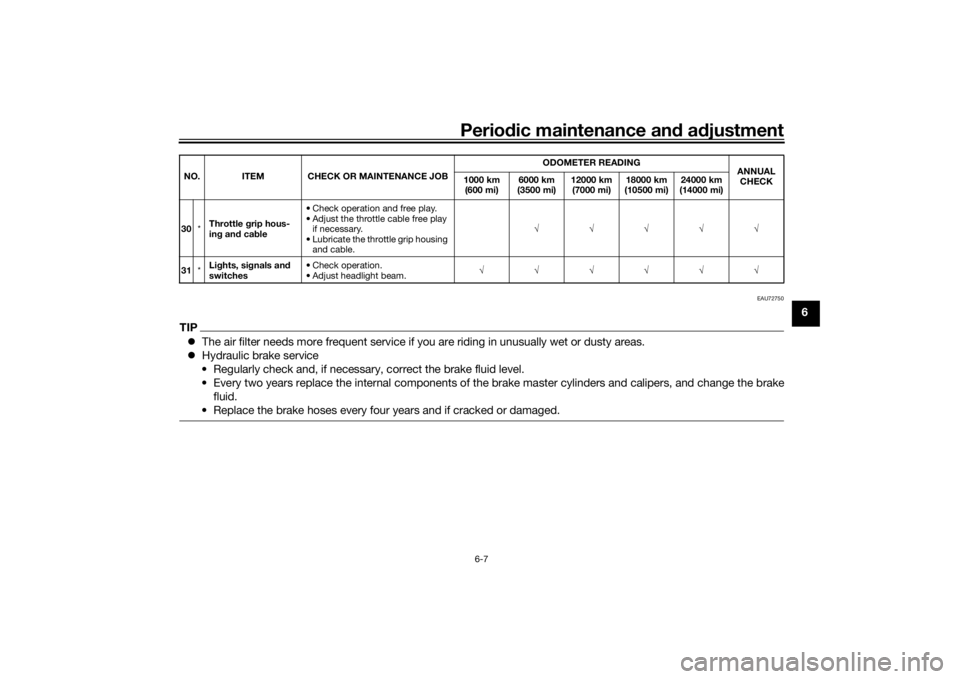
in g an d ca ble • Check operation and free play.
• Adjust the throttle cable free play
if necessary.
• Lubricate the throttle grip housing and cable. √√√√√
31 *Li
ghts, si gnals an d
switches • Check operation.
• Adjust headlight beam.
√√√√√√
NO. ITEM CHECK OR MAINTENANCE JOB
ODOMETER READING
ANNUAL
CHECK
1000 km
(600 mi) 6000 km
(3500 mi) 12000 km
(7000 mi) 18000 km
(10500 mi) 24000 km
(14000 mi)
UB5GE2E0.book Page 7 Thursday, July 30, 2020 3:08 PM
Page 52 of 94
Periodic maintenance an d a djustment
6-8
6
EAU18782
Removin g an d installin g cowl-
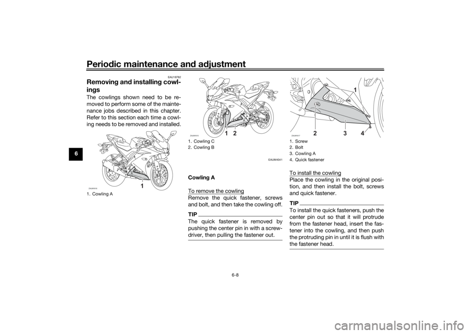
in gsThe cowlings shown need to be re-
moved to perform some of the mainte-
nance jobs described in this chapter.
Refer to this section each time a cowl-
ing needs to be removed and installed.
EAUM4041
Cowlin g A
To remove the cowlingRemove the quick fastener, screws
and bolt, and then take the cowling off.TIPThe quick fastener is removed by
pushing the center pin in with a screw-
driver, then pulling the fastener out.
To install the cowlingPlace the cowling in the original posi-
tion, and then install the bolt, screws
and quick fastener.TIPTo install the quick fasteners, push the
center pin out so that it will protrude
from the fastener head, insert the fas-
tener into the cowling, and then push
the protruding pin in until it is flush with
the fastener head.
1. Cowling AZAUM1616
1
1. Cowling C
2. Cowling BZAUM1615
1
2
1. Screw
2. Bolt
3. Cowling A
4. Quick fastenerZAUM1617
3
4
1
2
UB5GE2E0.book Page 8 Thursday, July 30, 2020 3:08 PM
Page 53 of 94
Periodic maintenance an d a djustment
6-9
6
Cowlin
g B
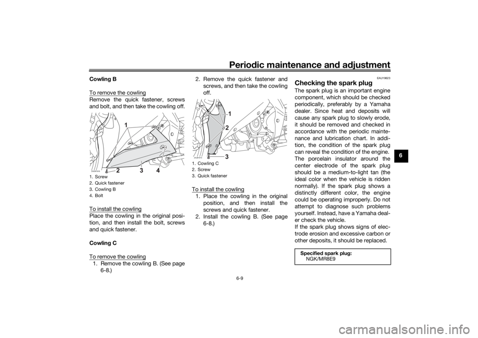
To remove the cowling
Remove the quick fastener, screws
and bolt, and then take the cowling off.
To install the cowlingPlace the cowling in the original posi-
tion, and then install the bolt, screws
and quick fastener.
Cowlin g C
To remove the cowling1. Remove the cowling B. (See page 6-8.) 2. Remove the quick fastener and
screws, and then take the cowling
off.
To install the cowling
1. Place the cowling in the original position, and then install the
screws and quick fastener.
2. Install the cowling B. (See page 6-8.)
EAU19623
Checkin g the spark plu gThe spark plug is an important engine
component, which should be checked
periodically, preferably by a Yamaha
dealer. Since heat and deposits will
cause any spark plug to slowly erode,
it should be removed and checked in
accordance with the periodic mainte-
nance and lubrication chart. In addi-
tion, the condition of the spark plug
can reveal the condition of the engine.
The porcelain insulator around the
center electrode of the spark plug
should be a medium-to-light tan (the
ideal color when the vehicle is ridden
normally). If the spark plug shows a
distinctly different color, the engine
could be operating improperly. Do not
attempt to diagnose such problems
yourself. Instead, have a Yamaha deal-
er check the vehicle.
If the spark plug shows signs of elec-
trode erosion and excessive carbon or
other deposits, it should be replaced.
1. Screw
2. Quick fastener
3. Cowling B
4. BoltZAUM1618
1
1. Cowling C
2. Screw
3. Quick fastenerZAUM1619
21
Specified spark plu g:
NGK/MR8E9
UB5GE2E0.book Page 9 Thursday, July 30, 2020 3:08 PM
Page 54 of 94
Periodic maintenance an d a djustment
6-10
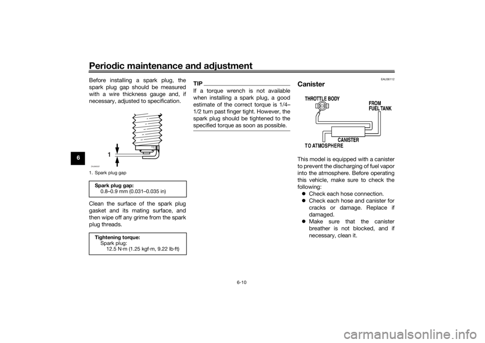
6 Before installing a spark plug, the
spark plug gap should be measured
with a wire thickness gauge and, if
necessary, adjusted to specification.
Clean the surface of the spark plug
gasket and its mating surface, and
then wipe off any grime from the spark
plug threads.
TIPIf a torque wrench is not available
when installing a spark plug, a good
estimate of the correct torque is 1/4–
1/2 turn past finger tight. However, the
spark plug should be tightened to the
specified torque as soon as possible.
EAU36112
CanisterThis model is equipped with a canister
to prevent the discharging of fuel vapor
into the atmosphere. Before operating
this vehicle, make sure to check the
following:
Check each hose connection.
Check each hose and canister for
cracks or damage. Replace if
damaged.
Make sure that the canister
breather is not blocked, and if
necessary, clean it.
1. Spark plug gapSpark plu g g ap:
0.8–0.9 mm (0.031–0.035 in)
Ti ghtenin g torque:
Spark plug: 12.5 N·m (1.25 kgf·m, 9.22 lb·ft)
1
ZAUM0037
UB5GE2E0.book Page 10 Thursday, July 30, 2020 3:08 PM
Page 55 of 94
Periodic maintenance an d a djustment
6-11
6
EAUM4051
En gine oil an d oil filter ele-
mentThe engine oil level should be checked
before each ride. In addition, the oil
must be changed and the oil filter ele-
ment replaced at the intervals specified
in the periodic maintenance and lubri-
cation chart.
To check the en gine oil level
1. Place the vehicle on a level sur- face and hold it in an upright posi-
tion. A slight tilt to the side can
result in a false reading.
2. Start the engine, warm it up for several minutes, and then turn it
off.
3. Wait a few minutes until the oil set- tles, remove the oil filler cap, wipe
the dipstick clean, insert it back
into the oil filler hole (without
screwing it in), and then remove it
again to check the oil level.
NOTICE: Do not operate the ve-
hicle until you know that the en-
g ine oil level is sufficient.
[ECA10012]
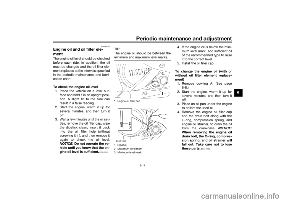
TIPThe engine oil should be between the
minimum and maximum level marks.
4. If the engine oil is below the mini-
mum level mark, add sufficient oil
of the recommended type to raise
it to the correct level.
5. Install the oil filler cap.
To chan ge the en gine oil (with or
without oil filter element replace-
ment) 1. Remove cowling A. (See page 6-8.)
2. Start the engine, warm it up for several minutes, and then turn it
off.
3. Place an oil pan under the engine to collect the used oil.
4. Remove the engine oil filler cap and the drain bolt along with the
O-ring, compression spring, and
engine oil strainer, to drain the oil
from the crankcase. NOTICE:
When removin g the eng ine oil
d rain bolt, the O-ring , compres-
sion sprin g, an d oil strainer will
fall out. Take care not to lose
these parts.
[ECA11002]
1. Engine oil filler cap
1. Dipstick
2. Maximum level mark
3. Minimum level markZAUM1610
1
2
3
ZAUE1300
UB5GE2E0.book Page 11 Thursday, July 30, 2020 3:08 PM
Page 56 of 94
Periodic maintenance an d a djustment
6-12
6
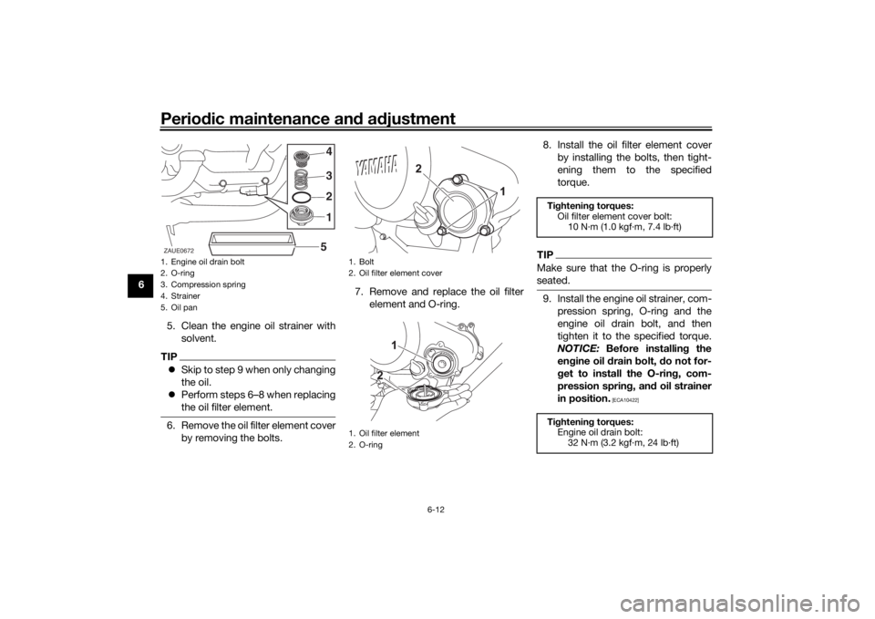
5. Clean the engine oil strainer withsolvent.
TIPSkip to step 9 when only changing
the oil.
Perform steps 6–8 when replacing
the oil filter element.6. Remove the oil filter element cover
by removing the bolts. 7. Remove and replace the oil filter
element and O-ring. 8. Install the oil filter element cover
by installing the bolts, then tight-
ening them to the specified
torque.
TIPMake sure that the O-ring is properly
seated.9. Install the engine oil strainer, com-pression spring, O-ring and the
engine oil drain bolt, and then
tighten it to the specified torque.
NOTICE: Before installin g the
en gine oil d rain bolt, do not for-
g et to install the O-rin g, com-
pression sprin g, an d oil strainer
in position.
[ECA10422]
1. Engine oil drain bolt
2. O-ring
3. Compression spring
4. Strainer
5. Oil pan
2 3 4
5 1
ZAUE0672
1. Bolt
2. Oil filter element cover
1. Oil filter element
2. O-ring
Ti
ghtenin g torques:
Oil filter element cover bolt: 10 N·m (1.0 kgf·m, 7.4 lb·ft)
Ti ghtenin g torques:
Engine oil drain bolt: 32 N·m (3.2 kgf·m, 24 lb·ft)
UB5GE2E0.book Page 12 Thursday, July 30, 2020 3:08 PM
Page 57 of 94
Periodic maintenance an d a djustment
6-13
6
10. Refill with the specified amount of
the recommended engine oil, and
then install and tighten the oil filler
cap.
NOTICE
ECA11621
In or der to prevent clutch slip-
pa ge (since the en gine oil also
lu bricates the clutch), do not
mix any chemical additives. Do
not use oils with a diesel speci-
fication of “CD” or oils of a hi gh-
er quality than specifie d. In
a ddition, do not use oils lab eled
“ENERGY CONSERVING II” or
hi gher.
Make sure that no forei gn mate-
rial enters the crankcase.
11. Start the engine, and then let it idle for several minutes while checking
it for oil leakage. If oil is leaking,
immediately turn the engine off
and check for the cause.
12. Turn the engine off, and then check the oil level and correct it if
necessary.
EAU85450
Why Yamalu beYAMALUBE oil is a Genuine YAMAHA
Part born of the engineers’ passion
and belief that engine oil is an impor-
tant liquid engine component. We form
teams of specialists in the fields of me-
chanical engineering, chemistry, elec-
tronics and track testing, and have
them develop the engine together with
the oil it will use. Yamalube oils take full
advantage of the base oil’s qualities
and blend in the ideal balance of addi-
tives to make sure the final oil clears
our performance standards. Thus,
Yamalube mineral, semisynthetic and
synthetic oils have their own distinct
characters and value. Yamaha’s expe-
rience gained over many years of re-
search and development into oil since
the 1960’s helps make Yamalube the
best choice for your Yamaha engine.
Recommen ded en gine oil:
See page 8-1.
Oil quantity: Oil change:
0.85 L (0.90 US qt, 0.75 Imp.qt)
With oil filter removal: 0.95 L (1.00 US qt, 0.84 Imp.qt)
UB5GE2E0.book Page 13 Thursday, July 30, 2020 3:08 PM
Page 58 of 94
Periodic maintenance an d a djustment
6-14
6
EAUS1203
CoolantThe coolant level should be checked
regularly. In addition, the coolant must
be changed at the intervals specified in
the periodic maintenance chart.TIPIf genuine Yamaha coolant is not avail-
able, use an ethylene glycol antifreeze
containing corrosion inhibitors for alu-
minum engines and mix with distilled
water at a 1:1 ratio.
EAUE3460
To check the coolant level
1. Place the vehicle on a level sur- face.
2. Remove cowling C of left side. (See page 6-8.)
3. Hold the vehicle in an upright po- sition.
TIPThe coolant level must be
checked on a cold engine since
the level varies with engine tem-
perature.
Make sure that the vehicle is posi-
tioned straight up when checking
the coolant level. A slight tilt to the
side can result in a false reading.4. Check the coolant level in the
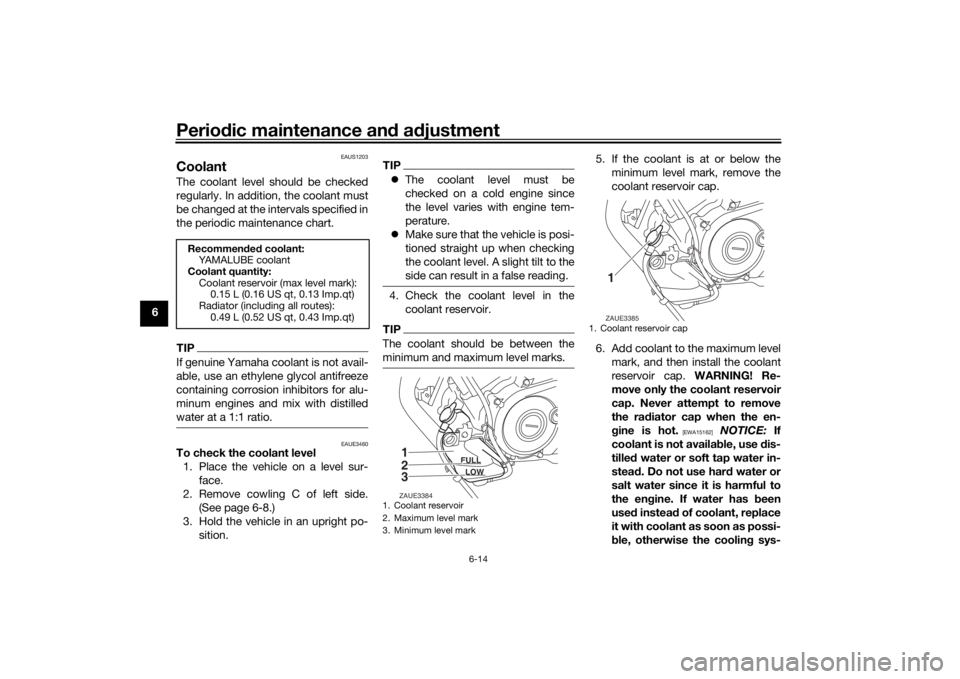
coolant reservoir.TIPThe coolant should be between the
minimum and maximum level marks.
5. If the coolant is at or below theminimum level mark, remove the
coolant reservoir cap.
6. Add coolant to the maximum level mark, and then install the coolant
reservoir cap. WARNING! Re-
move only the coolant reservoir
cap. Never attempt to remove
the ra diator cap when the en-
g ine is hot.
[EWA15162]
NOTICE: If
coolant is not availa ble, use dis-
tille d water or soft tap water in-
stead . Do not use har d water or
salt water since it is harmful to
the en gine. If water has been
use d instead of coolant, replace
it with coolant as soon as possi-
b le, otherwise the coolin g sys-
Recommen ded coolant:
YAMALUBE coolant
Coolant quantity: Coolant reservoir (max level mark):0.15 L (0.16 US qt, 0.13 Imp.qt)
Radiator (including all routes): 0.49 L (0.52 US qt, 0.43 Imp.qt)
1. Coolant reservoir
2. Maximum level mark
3. Minimum level mark
1
2
3
FULL
LOW
ZAUE3384
1. Coolant reservoir cap
1ZAUE3385
UB5GE2E0.book Page 14 Thursday, July 30, 2020 3:08 PM
Page 59 of 94
Periodic maintenance an d a djustment
6-15
6
tem will not
be protecte d
a g ainst frost an d corrosion. If
water has been a dded to the
coolant, have a Yamaha dealer
check the antifreeze content of
the coolant as soon as possi ble,
otherwise the effectiveness of
the coolant will be re duce d.
[ECA10473]
7. Install the cowling.
EAU33032
Chan gin g the coolant
The coolant must be changed at the in-
tervals specified in the periodic main-
tenance and lubrication chart. Have a
Yamaha dealer change the coolant.
WARNING! Never attempt to remove the ra diator cap when the en gine is
hot.
[EWA10382] EAUM2391
Replacin
g the air filter ele-
ment an d cleanin g the check
hoseThe air filter element should be re-
placed at the intervals specified in the
periodic maintenance and lubrication
chart. Have a Yamaha dealer replace
the air filter element more frequently if
you are riding in unusually wet or dusty
areas. In addition, the air filter check
hose must be frequently checked and
cleaned if necessary.
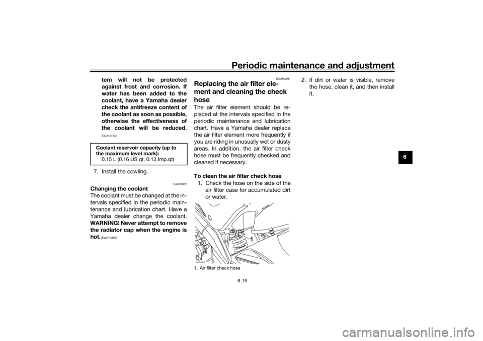
To clean the air filter check hose
1. Check the hose on the side of the air filter case for accumulated dirt
or water. 2. If dirt or water is visible, remove
the hose, clean it, and then install
it.
Coolant reservoir capacity (up to
the maximum level mark):0.15 L (0.16 US qt, 0.13 Imp.qt)
1. Air filter check hoseZAUM1594
UB5GE2E0.book Page 15 Thursday, July 30, 2020 3:08 PM
Page 60 of 94
Periodic maintenance an d a djustment
6-16
6
EAU34302
A djustin g the eng ine idlin g
spee dThe engine idling speed must be
checked and, if necessary, adjusted as
follows at the intervals specified in the
periodic maintenance and lubrication
chart.
The engine should be warm before
making this adjustment.
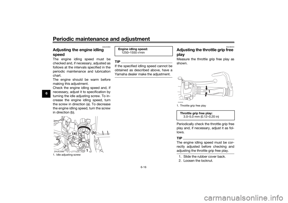
Check the engine idling speed and, if
necessary, adjust it to specification by
turning the idle adjusting screw. To in-
crease the engine idling speed, turn
the screw in direction (a). To decrease
the engine idling speed, turn the screw
in direction (b).
TIPIf the specified idling speed cannot be
obtained as described above, have a
Yamaha dealer make the adjustment.
EAU48434
A djustin g the throttle grip free
playMeasure the throttle grip free play as
shown.
Periodically check the throttle grip free
play and, if necessary, adjust it as fol-
lows.TIPThe engine idling speed must be cor-
rectly adjusted before checking and
adjusting the throttle grip free play.1. Slide the rubber cover back.
2. Loosen the locknut.
1. Idle adjusting screwZAUE3388
(a)
(b)
1
En gine i dlin g spee d:
1250–1550 r/min
1. Throttle grip free playThrottle grip free play:
3.0–5.0 mm (0.12–0.20 in)ZAUM1595
1
UB5GE2E0.book Page 16 Thursday, July 30, 2020 3:08 PM