lock YAMAHA YZF-R125 2021 Owners Manual
[x] Cancel search | Manufacturer: YAMAHA, Model Year: 2021, Model line: YZF-R125, Model: YAMAHA YZF-R125 2021Pages: 94, PDF Size: 3.34 MB
Page 6 of 94

Table of contentsSafety information ............................ 1-1
Description ....................................... 2-1
Left view ......................................... 2-1
Right view ....................................... 2-2
Controls and instruments ............... 2-3
Instrument an d control functions ... 3-1
Main switch/steering lock............... 3-1
Indicator lights and warning lights............................................ 3-2
Multi-function meter unit ................ 3-4
Handlebar switches ...................... 3-12
Clutch lever .................................. 3-13
Shift pedal .................................... 3-14
Brake lever.................................... 3-14
Brake pedal .................................. 3-14
ABS .............................................. 3-15
Fuel tank cap ................................ 3-16
Fuel ............................................... 3-16
Fuel tank breather hose and overflow hose ............................ 3-18
Catalytic converter ....................... 3-19
Seats ............................................ 3-19
Sidestand ..................................... 3-20
Ignition circuit cut-off system ....... 3-21 For your safety – pre-operation
checks
............................................... 4-1
Operation an d important ri din g
points ................................................. 5-1
Engine break-in ............................... 5-1
Starting the engine .......................... 5-2
Shifting ............................................ 5-3
Tips for reducing fuel consumption ................................ 5-4
Parking ............................................ 5-4
Perio dic maintenance an d
a d justment ........................................ 6-1
Tool kit ............................................ 6-2
Periodic maintenance chart for the emission control system .............. 6-3
General maintenance and lubrication chart ........................... 6-4
Removing and installing cowlings... 6-8
Checking the spark plug ................. 6-9
Canister ......................................... 6-10
Engine oil and oil filter element ..... 6-11
Why Yamalube .............................. 6-13
Coolant.......................................... 6-14
Replacing the air filter element
and cleaning the check hose..... 6-15
Adjusting the engine idling speed ......................................... 6-16
Adjusting the throttle grip free play ............................................ 6-16 Valve clearance............................. 6-17
Tires .............................................. 6-17
Cast wheels .................................. 6-19
Adjusting the clutch lever free
play ............................................ 6-20
Checking the front brake lever free play..................................... 6-21
Adjusting the brake pedal free
play ............................................ 6-21
Brake light switches ..................... 6-22
Checking the front and rear brake pads .......................................... 6-22
Checking the brake fluid level ...... 6-23
Changing the brake fluid .............. 6-24
Drive chain slack........................... 6-25
Cleaning and lubricating the drive chain.......................................... 6-26
Checking and lubricating the cables ........................................ 6-27
Checking and lubricating the
throttle grip and cable ............... 6-27
Checking and lubricating the brake and shift pedals............... 6-27
Checking and lubricating the brake and clutch levers ............. 6-28
Checking and lubricating the
sidestand................................... 6-29
Lubricating the rear suspension ... 6-29
Checking the front fork ................. 6-29
Checking the steering................... 6-30
Checking the wheel bearings ....... 6-30UB5GE2E0.book Page 1 Thursday, July 30, 2020 3:08 PM
Page 14 of 94
Description
2-2
2
EAU10421
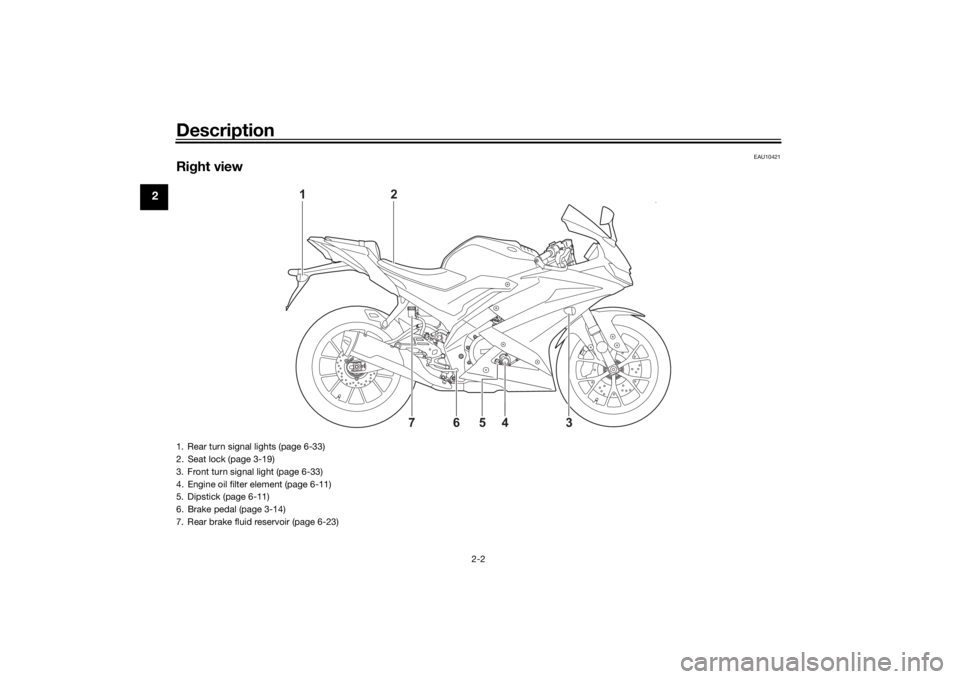
Right view
2
1
4
76
3
5
1. Rear turn signal lights (page 6-33)
2. Seat lock (page 3-19)
3. Front turn signal light (page 6-33)
4. Engine oil filter element (page 6-11)
5. Dipstick (page 6-11)
6. Brake pedal (page 3-14)
7. Rear brake fluid reservoir (page 6-23)UB5GE2E0.book Page 2 Thursday, July 30, 2020 3:08 PM
Page 15 of 94

Description
2-3
2
EAU10431
Controls and instruments
12 34 6
578
1. Clutch lever (page 3-13)
2. Left handlebar switches (page 3-12)
3. Multi-function meter unit (page 3-4)
4. Main switch/steering lock (page 3-1)
5. Front brake fluid reservoir (page 6-23)
6. Right handlebar switches (page 3-12)
7. Throttle grip (page 6-16)
8. Brake lever (page 3-14)
UB5GE2E0.book Page 3 Thursday, July 30, 2020 3:08 PM
Page 16 of 94
Instrument and control functions
3-1
3
EAU10462
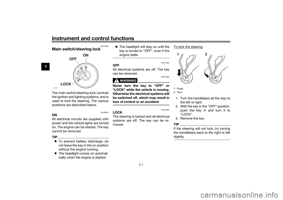
Main switch/steerin g lockThe main switch/steering lock controls
the ignition and lighting systems, and is
used to lock the steering. The various
positions are described below.
EAU85050
ON
All electrical circuits are supplied with
power and the vehicle lights are turned
on. The engine can be started. The key
cannot be removed.TIP To prevent battery discharge, do
not leave the key in the on position
without the engine running.
The headlight comes on automat-
ically when the engine is started.
The headlight will stay on until the
key is turned to “OFF”, even if the
engine stalls.
EAU10662
OFF
All electrical systems are off. The key
can be removed.
WARNING
EWA10062
Never turn the key to “OFF” or
“LOCK” while the vehicle is movin g.
Otherwise the electrical systems will
b e switche d off, which may result in
loss of control or an acci dent.
EAU10696
LOCK
The steering is locked and all electrical
systems are off. The key can be re-
moved. To lock the steering
1. Turn the handlebars all the way to
the left or right.
2. With the key in the “OFF” position, push the key in and turn it to
“LOCK”.
3. Remove the key.TIPIf the steering will not lock, try turning
the handlebars back to the right or left
slightly.
ZAUE0971
1. Push.
2. Turn.12
UB5GE2E0.book Page 1 Thursday, July 30, 2020 3:08 PM
Page 17 of 94
Instrument and control functions
3-2
3
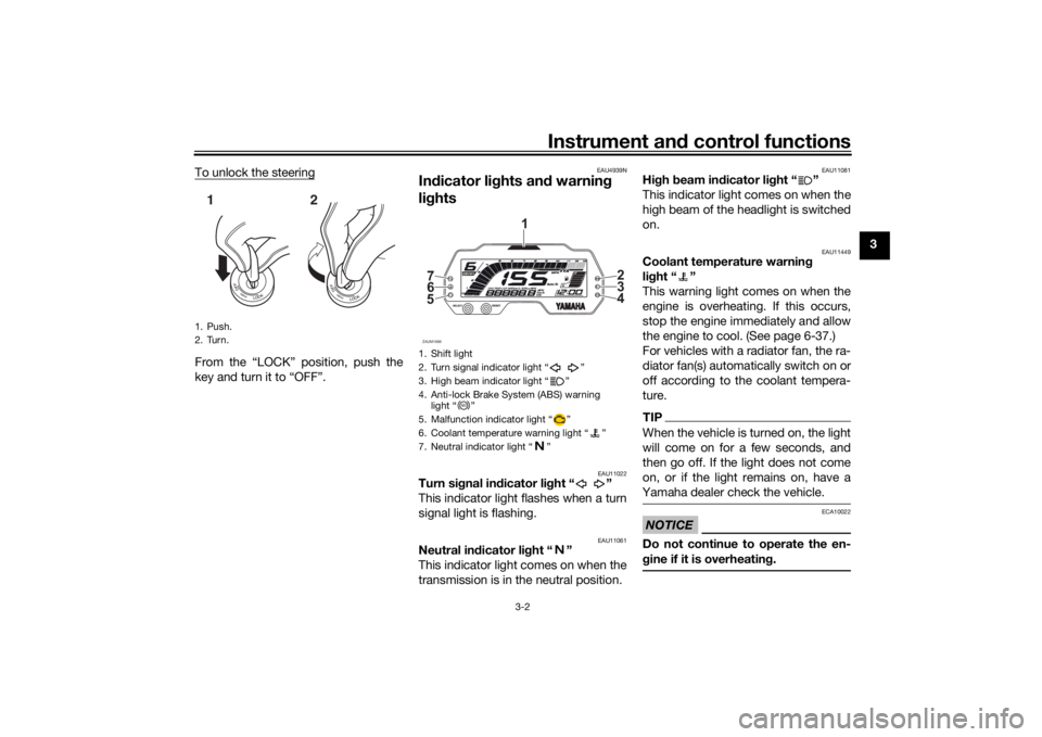
To unlock the steering
From the “LOCK” position, push the
key and turn it to “OFF”.
EAU4939N
In
dicator li ghts an d warnin g
lig hts
EAU11022
Turn si gnal in dicator li ght “ ”
This indicator light flashes when a turn
signal light is flashing.
EAU11061
Neutral in dicator li ght “ ”
This indicator light comes on when the
transmission is in the neutral position.
EAU11081
Hi gh beam in dicator li ght “ ”
This indicator light comes on when the
high beam of the headlight is switched
on.
EAU11449
Coolant temperature warnin g
li g ht “ ”
This warning light comes on when the
engine is overheating. If this occurs,
stop the engine immediately and allow
the engine to cool. (See page 6-37.)
For vehicles with a radiator fan, the ra-
diator fan(s) automatically switch on or
off according to the coolant tempera-
ture.TIPWhen the vehicle is turned on, the light
will come on for a few seconds, and
then go off. If the light does not come
on, or if the light remains on, have a
Yamaha dealer check the vehicle. NOTICE
ECA10022
Do not continue to operate the en-
g ine if it is overheatin g.
1. Push.
2. Turn.12
1. Shift light
2. Turn signal indicator light “ ”
3. High beam indicator light “ ”
4. Anti-lock Brake System (ABS) warning
light “ ”
5. Malfunction indicator light “ ”
6. Coolant temperature warning light “ ”
7. Neutral indicator light “ ”ZAUM15665 6 7
2
3
4
1
ABS
UB5GE2E0.book Page 2 Thursday, July 30, 2020 3:08 PM
Page 18 of 94
Instrument and control functions
3-3
3
EAU88330
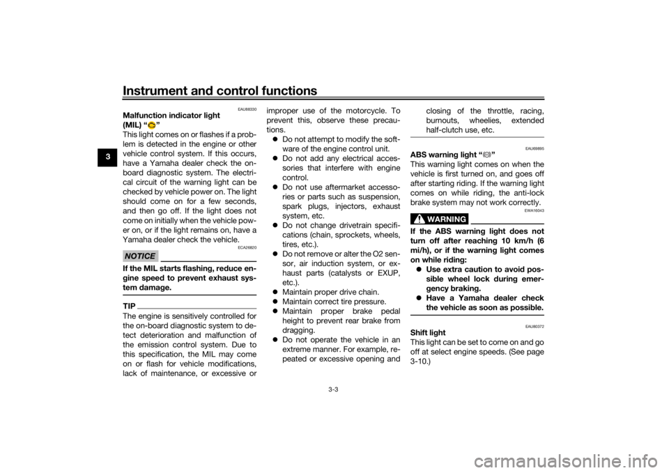
Malfunction in dicator li ght
(MIL) “ ”
This light comes on or flashes if a prob-
lem is detected in the engine or other
vehicle control system. If this occurs,
have a Yamaha dealer check the on-
board diagnostic system. The electri-
cal circuit of the warning light can be
checked by vehicle power on. The light
should come on for a few seconds,
and then go off. If the light does not
come on initially when the vehicle pow-
er on, or if the light remains on, have a
Yamaha dealer check the vehicle.NOTICE
ECA26820
If the MIL starts flashin g, re duce en-
g ine speed to prevent exhaust sys-
tem damag e.TIPThe engine is sensitively controlled for
the on-board diagnostic system to de-
tect deterioration and malfunction of
the emission control system. Due to
this specification, the MIL may come
on or flash for vehicle modifications,
lack of maintenance, or excessive or improper use of the motorcycle. To
prevent this, observe these precau-
tions.
Do not attempt to modify the soft-
ware of the engine control unit.
Do not add any electrical acces-
sories that interfere with engine
control.
Do not use aftermarket accesso-
ries or parts such as suspension,
spark plugs, injectors, exhaust
system, etc.
Do not change drivetrain specifi-
cations (chain, sprockets, wheels,
tires, etc.).
Do not remove or alter the O2 sen-
sor, air induction system, or ex-
haust parts (catalysts or EXUP,
etc.).
Maintain proper drive chain.
Maintain correct tire pressure.
Maintain proper brake pedal
height to prevent rear brake from
dragging.
Do not operate the vehicle in an
extreme manner. For example, re-
peated or excessive opening and closing of the throttle, racing,
burnouts, wheelies, extended
half-clutch use, etc.
EAU69895
ABS warnin
g li ght “ ”
This warning light comes on when the
vehicle is first turned on, and goes off
after starting riding. If the warning light
comes on while riding, the anti-lock
brake system may not work correctly.
WARNING
EWA16043
If the ABS warnin g li ght does not
turn off after reachin g 10 km/h (6
mi/h), or if the warnin g li ght comes
on while ri din g:
Use extra caution to avoi d pos-
si ble wheel lock d uring emer-
g ency brakin g.
Have a Yamaha dealer check
the vehicle as soon as possi ble.
EAU80372
Shift li ght
This light can be set to come on and go
off at select engine speeds. (See page
3-10.)
ABS
UB5GE2E0.book Page 3 Thursday, July 30, 2020 3:08 PM
Page 19 of 94
Instrument and control functions
3-4
3
TIPWhen the vehicle is turned on, the light
will come on for a few seconds and
then go off. If the light does not come
on, have a Yamaha dealer check the
vehicle.
EAUM4011
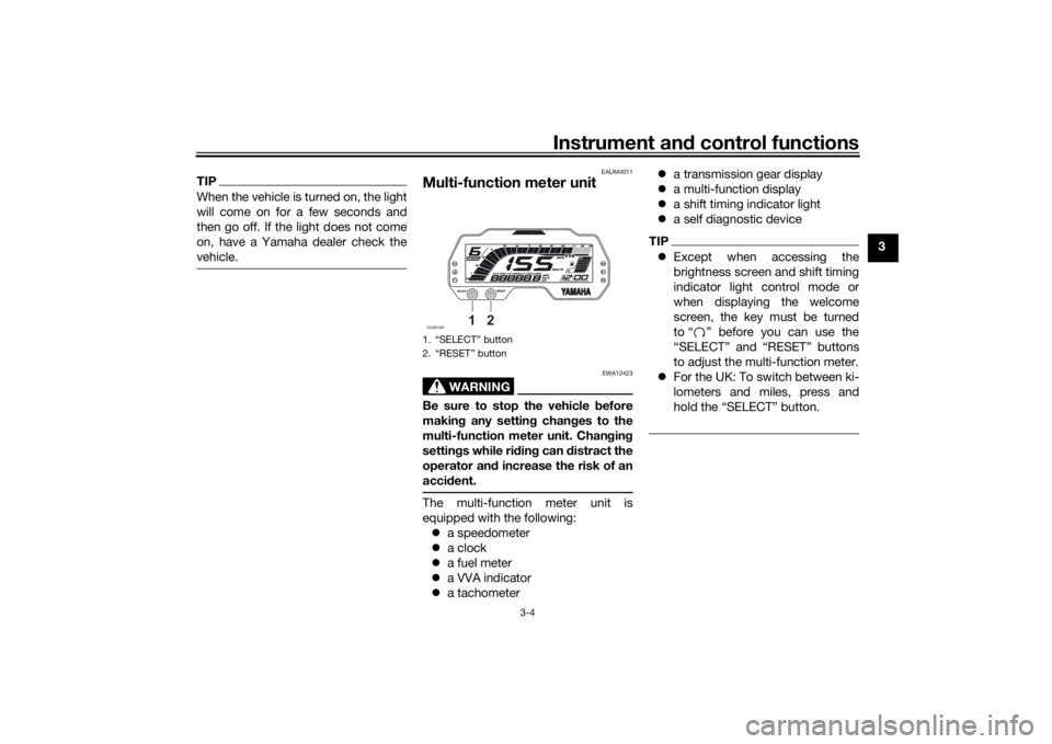
Multi-function meter unit
WARNING
EWA12423
Be sure to stop the vehicle before
makin g any settin g chan ges to the
multi-function meter unit. Chan gin g
settin gs while ri din g can distract the
operator an d increase the risk of an
acci dent.The multi-function meter unit is
equipped with the following:
a speedometer
a clock
a fuel meter
a VVA indicator
a tachometer
a transmission gear display
a multi-function display
a shift timing indicator light
a self diagnostic device
TIPExcept when accessing the
brightness screen and shift timing
indicator light control mode or
when displaying the welcome
screen, the key must be turned
to “ ” before you can use the
“SELECT” and “RESET” buttons
to adjust the multi-function meter.
For the UK: To switch between ki-
lometers and miles, press and
hold the “SELECT” button.
1. “SELECT” button
2. “RESET” buttonZAUM1567
1
2
UB5GE2E0.book Page 4 Thursday, July 30, 2020 3:08 PM
Page 20 of 94
Instrument and control functions
3-5
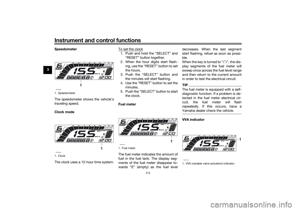
3 Speed
ometer
The speedometer shows the vehicle’s
traveling speed.
Clock mo de
The clock uses a 12-hour time system. To set the clock
1. Push and hold the “SELECT” and
“RESET” button together.
2. When the hour digits start flash- ing, use the “RESET” button to set
the hours.
3. Push the “SELECT” button and the minutes will start flashing.
4. Use the “RESET” button to set the minutes.
5. Push the “SELECT” button to start the clock.
Fuel meter
The fuel meter indicates the amount of
fuel in the fuel tank. The display seg-
ments of the fuel meter disappear to-
wards “E” (empty) as the fuel level decreases. When the last segment
start flashing, refuel as soon as possi-
ble.
When the key is turned to “ ”, the dis-
play segments of the fuel meter will
sweep once across the fuel level range
and then return to the current amount
in order to test the electrical circuit.
TIPThe fuel meter is equipped with a self-
diagnostic function. If a problem is de-
tected in the fuel meter electrical cir-
cuit, the fuel meter will flash
repeatedly. If this occurs, have a
Yamaha dealer check the vehicle.VVA in dicator
1. Speedometer
1. ClockZAUM1568
1
ZAUM1569
1
1. Fuel meterZAUM1570
1
1. VVA (variable valve actuation) indicatorZAUM1571
1
UB5GE2E0.book Page 5 Thursday, July 30, 2020 3:08 PM
Page 22 of 94
Instrument and control functions
3-7
3 1” and “TRIP 2”, instantaneous fuel
consumption mode “km/L” or “L/100
km”, average fuel consumption mode
“AVE_ _._ km/L” or “AVE_ _._ L/100
km” and average speed mode “AVE_
_._ km/h” in the following order:
ODO
→ TRIP 1 → TRIP 2 → km/L or
L/100 km → AVE_ _._ km/L or AVE_ _._
L/100 km → AVE_ _._ km/h → ODO
For the UK:
Push the “SELECT” button to switch
the display between the odometer
mode “ODO”, tripmeters mode “TRIP
1” and “TRIP 2”, instantaneous fuel
consumption mode “km/L” or “L/100
km” or “MPG”, average fuel consump-
tion mode “AVE_ _._ km/L”, “AVE_ _._
L/100 km” or “AVE_ _ _._ MPG” and
average speed mode “AVE_ _._ km/h”
or “AVE_ _._ MPH” in the following or-
der:
ODO → TRIP 1 → TRIP 2 → km/L or
L/100 km or MPG → AVE_ _._ km/L or
AVE_ _._ L/100 km or AVE_ _ _._
MPG → AVE_ _._ km/h or AVE_ _._
MPH → ODO Push the “RESET” button to switch
display backward.
If the last segment of the fuel meter
starts flashing, the display automati-
cally changes to the fuel reserve trip-
meter mode “TRIP F” and starts
counting the distance traveled from
that point. In that case, push the “SE-
LECT” button to switch the display be-
tween the various tripmeter, odometer,
instantaneous fuel consumption, aver-
age fuel consumption, and average
speed modes in the following order:
TRIP F
→ km/L or L/100 km → AVE_
_._ km/L or AVE_ _._ L/100 km → AVE_
_._ km/h → ODO → TRIP 1 → TRIP 2
→ TRIP F
For the UK:
TRIP F → km/L, L/100 km or MPG →
AVE_ _._ km/L, AVE_ _._ L/100 km or
AVE_ _ _._ MPG → AVE_ _._ km/h or
AVE_ _._ MPH → ODO → TRIP 1 →
TRIP 2 → TRIP F To reset a tripmeter, select it by push-
ing the “SELECT” button and then
push and hold the “RESET” button.
If you do not reset the fuel reserve trip-
meter manually, it resets itself auto-
matically and the display returns to the
prior mode after refueling and traveling
5 km (3 mi).
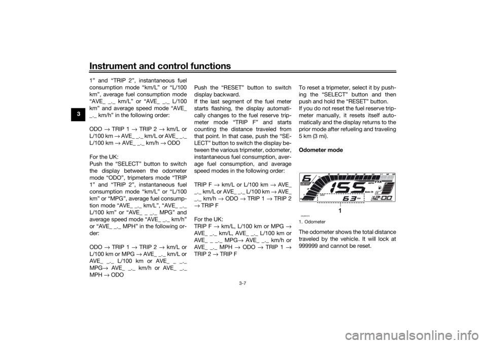
O
dometer mo de
The odometer shows the total distance
traveled by the vehicle. It will lock at
999999 and cannot be reset.
1. OdometerZAUM1575
1
UB5GE2E0.book Page 7 Thursday, July 30, 2020 3:08 PM
Page 30 of 94
Instrument and control functions
3-15
3
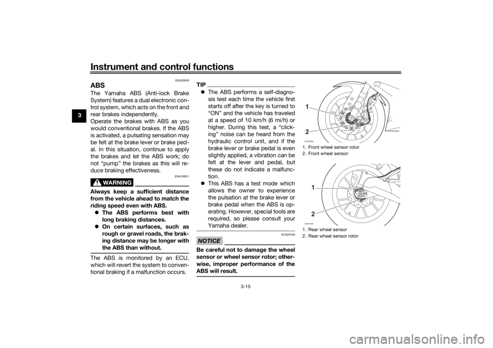
EAU63040
ABSThe Yamaha ABS (Anti-lock Brake
System) features a dual electronic con-
trol system, which acts on the front and
rear brakes independently.
Operate the brakes with ABS as you
would conventional brakes. If the ABS
is activated, a pulsating sensation may
be felt at the brake lever or brake ped-
al. In this situation, continue to apply
the brakes and let the ABS work; do
not “pump” the brakes as this will re-
duce braking effectiveness.
WARNING
EWA16051
Always keep a sufficient d istance
from the vehicle ahea d to match the
ri din g speed even with ABS.
The ABS performs best with
lon g b rakin g d istances.
On certain surfaces, such as
rou gh or g ravel roa ds, the b rak-
in g d istance may b e longer with
the ABS than without.The ABS is monitored by an ECU,
which will revert the system to conven-
tional braking if a malfunction occurs.
TIP The ABS performs a self-diagno-
sis test each time the vehicle first
starts off after the key is turned to
“ON” and the vehicle has traveled
at a speed of 10 km/h (6 mi/h) or
higher. During this test, a “click-
ing” noise can be heard from the
hydraulic control unit, and if the
brake lever or brake pedal is even
slightly applied, a vibration can be
felt at the lever and pedal, but
these do not indicate a malfunc-
tion.
This ABS has a test mode which
allows the owner to experience
the pulsation at the brake lever or
brake pedal when the ABS is op-
erating. However, special tools are
required, so please consult your
Yamaha dealer.NOTICE
ECA20100
Be careful not to damag e the wheel
sensor or wheel sensor rotor; other-
wise, improper performance of the
ABS will result.
1. Front wheel sensor rotor
2. Front wheel sensor
1. Rear wheel sensor
2. Rear wheel sensor rotorZAUM158912ZAUM1590
12
UB5GE2E0.book Page 15 Thursday, July 30, 2020 3:08 PM