torque YAMAHA YZF-R125 2021 Owners Manual
[x] Cancel search | Manufacturer: YAMAHA, Model Year: 2021, Model line: YZF-R125, Model: YAMAHA YZF-R125 2021Pages: 94, PDF Size: 3.34 MB
Page 35 of 94
Instrument and control functions
3-20
3
2. Install the passenger seat by in-
stalling and tightening the nut to
the specified torque.
3. Install the plastic cover.
Ri der seat
To remove the rider seat
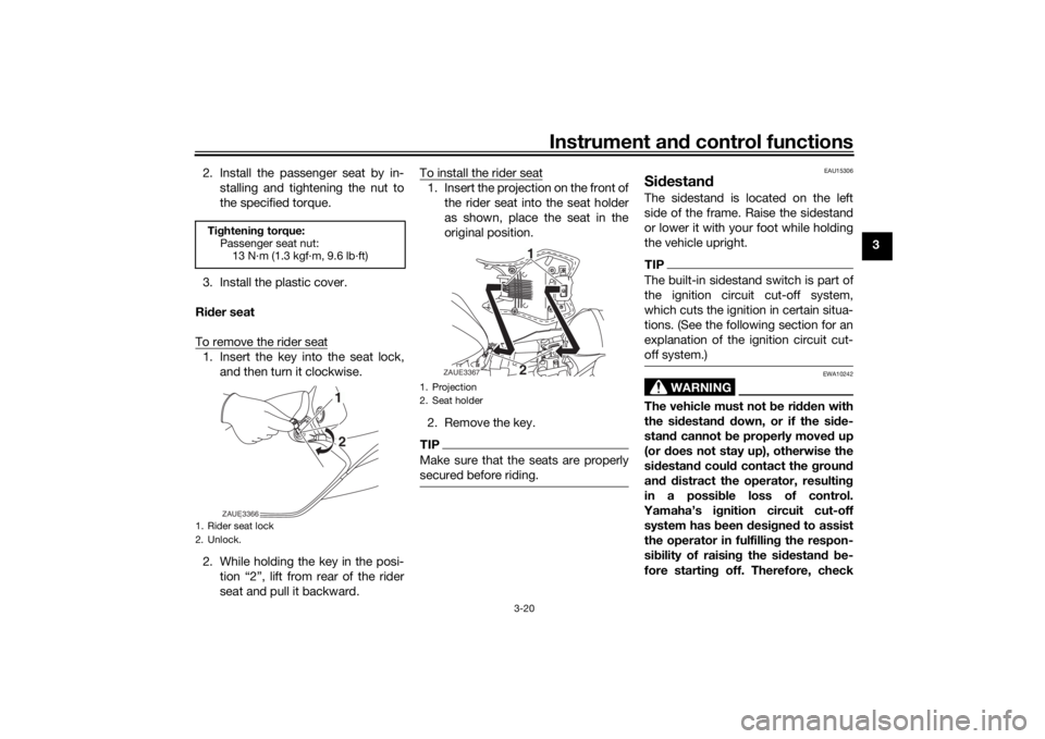
1. Insert the key into the seat lock, and then turn it clockwise.
2. While holding the key in the posi- tion “2”, lift from rear of the rider
seat and pull it backward. To install the rider seat
1. Insert the projection on the front of
the rider seat into the seat holder
as shown, place the seat in the
original position.
2. Remove the key.TIPMake sure that the seats are properly
secured before riding.
EAU15306
Si destan dThe sidestand is located on the left
side of the frame. Raise the sidestand
or lower it with your foot while holding
the vehicle upright.TIPThe built-in sidestand switch is part of
the ignition circuit cut-off system,
which cuts the ignition in certain situa-
tions. (See the following section for an
explanation of the ignition circuit cut-
off system.)
WARNING
EWA10242
The vehicle must not be ri dden with
the si destan d d own, or if the si de-
stan d cannot b e properly move d up
(or does not stay up), otherwise the
si destan d coul d contact the groun d
an d d istract the operator, resultin g
in a possib le loss of control.
Yamaha’s ig nition circuit cut-off
system has been desi gne d to assist
the operator in fulfillin g the respon-
si bility of raisin g the sid estand b e-
fore startin g off. Therefore, check
Ti ghtenin g torque:
Passenger seat nut: 13 N·m (1.3 kgf·m, 9.6 lb·ft)1. Rider seat lock
2. Unlock.
21
ZAUE3366
1. Projection
2. Seat holder
21
ZAUE3367
UB5GE2E0.book Page 20 Thursday, July 30, 2020 3:08 PM
Page 46 of 94
Periodic maintenance an d a djustment
6-2
6
EAU85230
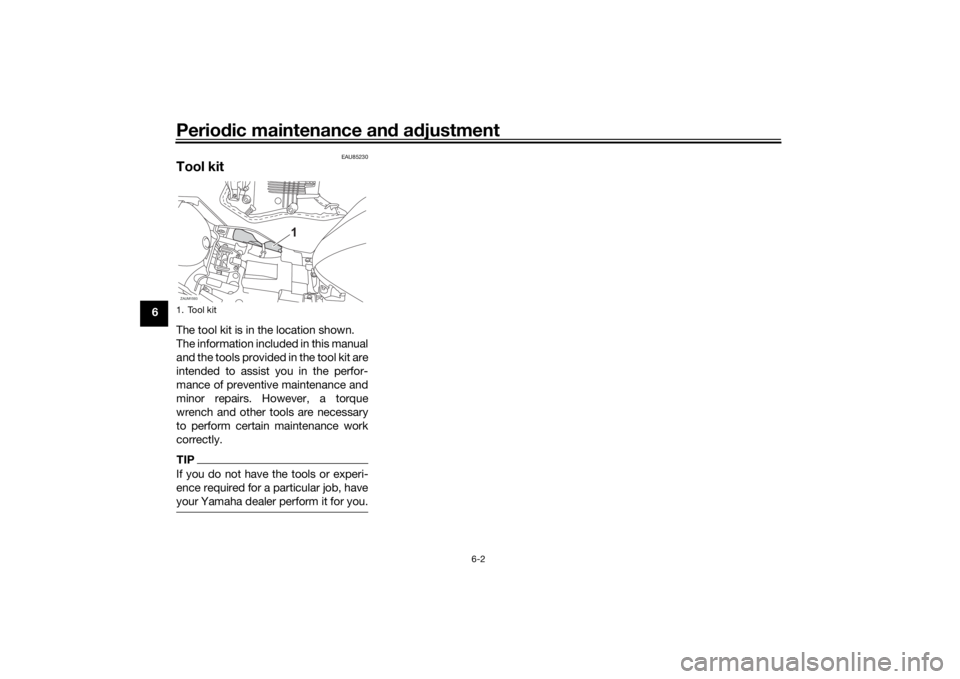
Tool kitThe tool kit is in the location shown.
The information included in this manual
and the tools provided in the tool kit are
intended to assist you in the perfor-
mance of preventive maintenance and
minor repairs. However, a torque
wrench and other tools are necessary
to perform certain maintenance work
correctly.TIPIf you do not have the tools or experi-
ence required for a particular job, have
your Yamaha dealer perform it for you.1. Tool kitZAUM1593
1
UB5GE2E0.book Page 2 Thursday, July 30, 2020 3:08 PM
Page 54 of 94
Periodic maintenance an d a djustment
6-10
6 Before installing a spark plug, the
spark plug gap should be measured
with a wire thickness gauge and, if
necessary, adjusted to specification.
Clean the surface of the spark plug
gasket and its mating surface, and
then wipe off any grime from the spark
plug threads.
TIPIf a torque wrench is not available
when installing a spark plug, a good
estimate of the correct torque is 1/4–
1/2 turn past finger tight. However, the
spark plug should be tightened to the
specified torque as soon as possible.
EAU36112
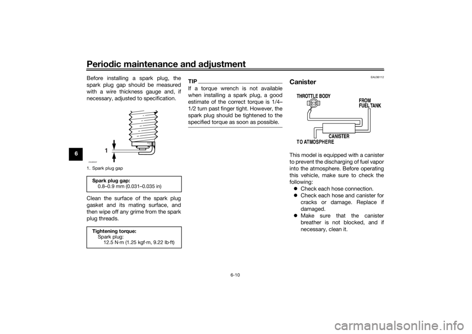
CanisterThis model is equipped with a canister
to prevent the discharging of fuel vapor
into the atmosphere. Before operating
this vehicle, make sure to check the
following:
Check each hose connection.
Check each hose and canister for
cracks or damage. Replace if
damaged.
Make sure that the canister
breather is not blocked, and if
necessary, clean it.
1. Spark plug gapSpark plu g g ap:
0.8–0.9 mm (0.031–0.035 in)
Ti ghtenin g torque:
Spark plug: 12.5 N·m (1.25 kgf·m, 9.22 lb·ft)
1
ZAUM0037
UB5GE2E0.book Page 10 Thursday, July 30, 2020 3:08 PM
Page 56 of 94
Periodic maintenance an d a djustment
6-12
6
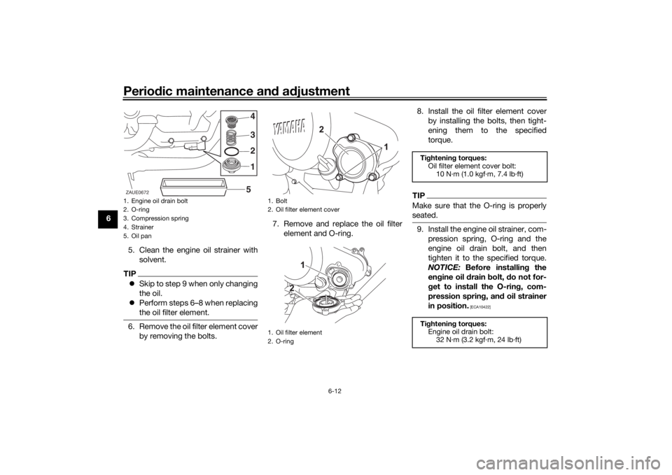
5. Clean the engine oil strainer withsolvent.
TIPSkip to step 9 when only changing
the oil.
Perform steps 6–8 when replacing
the oil filter element.6. Remove the oil filter element cover
by removing the bolts. 7. Remove and replace the oil filter
element and O-ring. 8. Install the oil filter element cover
by installing the bolts, then tight-
ening them to the specified
torque.
TIPMake sure that the O-ring is properly
seated.9. Install the engine oil strainer, com-pression spring, O-ring and the
engine oil drain bolt, and then
tighten it to the specified torque.
NOTICE: Before installin g the
en gine oil d rain bolt, do not for-
g et to install the O-rin g, com-
pression sprin g, an d oil strainer
in position.
[ECA10422]
1. Engine oil drain bolt
2. O-ring
3. Compression spring
4. Strainer
5. Oil pan
2 3 4
5 1
ZAUE0672
1. Bolt
2. Oil filter element cover
1. Oil filter element
2. O-ring
Ti
ghtenin g torques:
Oil filter element cover bolt: 10 N·m (1.0 kgf·m, 7.4 lb·ft)
Ti ghtenin g torques:
Engine oil drain bolt: 32 N·m (3.2 kgf·m, 24 lb·ft)
UB5GE2E0.book Page 12 Thursday, July 30, 2020 3:08 PM
Page 70 of 94
Periodic maintenance an d a djustment
6-26
6 3. Tighten the axle nut, then the lock-
nuts to their specified torques.
4. Make sure that the drive chain pullers are in the same position,
the drive chain slack is correct,
and the drive chain moves
smoothly.
EAU23026
Cleanin g an d lu bricatin g the
d rive chainThe drive chain must be cleaned and
lubricated at the intervals specified in
the periodic maintenance and lubrica-
tion chart, otherwise it will quickly wear
out, especially when riding in dusty or
wet areas. Service the drive chain as
follows.NOTICE
ECA10584
The drive chain must b e lubricated
after washin g the motorcycle, ri din g
in the rain or ri din g in wet areas.1. Clean the drive chain with kero-
sene and a small soft brush.
NOTICE: To prevent d amaging
the O-rin gs, do not clean the
d rive chain with steam cleaners,
hi gh-pressure washers or inap-
propriate solvents.
[ECA11122]
2. Wipe the drive chain dry.
3. Thoroughly lubricate the drive chain with a special O-ring chain
lubricant. NOTICE: Do not use
en gine oil or any other lu bri-
cants for the drive chain, as they may contain su
bstances that
coul d damag e the O-rin gs.
[ECA11112]
Ti ghtenin g torques:
Axle nut: 85 N·m (8.5 kgf·m, 63 lb·ft)
Locknut:
15 N·m (1.5 kgf·m, 11 lb·ft)
UB5GE2E0.book Page 26 Thursday, July 30, 2020 3:08 PM