traction control YAMAHA YZF-R1M 2020 Owners Manual
[x] Cancel search | Manufacturer: YAMAHA, Model Year: 2020, Model line: YZF-R1M, Model: YAMAHA YZF-R1M 2020Pages: 136, PDF Size: 16.15 MB
Page 18 of 136
Special features
3-1
3
EAU6629B
YRC (Yamaha Ride Control)Yamaha Ride Control is a system that
incorporates numerous sensors and
controls to support an improved riding
experience. The vehicle senses and
can react to forces along the longitudi-
nal (front-to-back), lateral (left-to-right),
and vertical (up-and-down) axes. Lean
angle and G-force accelerations are
also detected. This information is pro-
cessed multiple times a second and
the related physical systems are auto-
matically adjusted as necessary. The
following functions represent individual
YRC items which can be turned on/off
or adjusted to suit various riders and
riding conditions. For setting details,
see pages 4-11 and 4-16.
WARNING
EWA18221
The Yamaha Ri de Control (YRC) sys-
tem is not a su bstitute for the use of
proper ri din g techniques or the ex-
pertise of the operator. This system
cannot prevent loss of control
caused b y ri der errors such as trav-
elin g faster than warranted b y roa d
an d traffic con ditions, inclu din g loss of traction
due to excessive spee d
when enterin g turns, when acceler-
atin g har d at a sharp lean an gle, or
while brakin g, an d it cannot prevent
front wheel slip or front wheel lift. As
with any motorcycle, always ri de
within in your limits, be aware of sur-
roun din g con ditions, an d ri de ap-
propriately for those con ditions.
Become thorou ghly familiar with the
way the motorcycle han dles with
various YRC settin gs before at-
temptin g more a dvance d maneu-
vers.
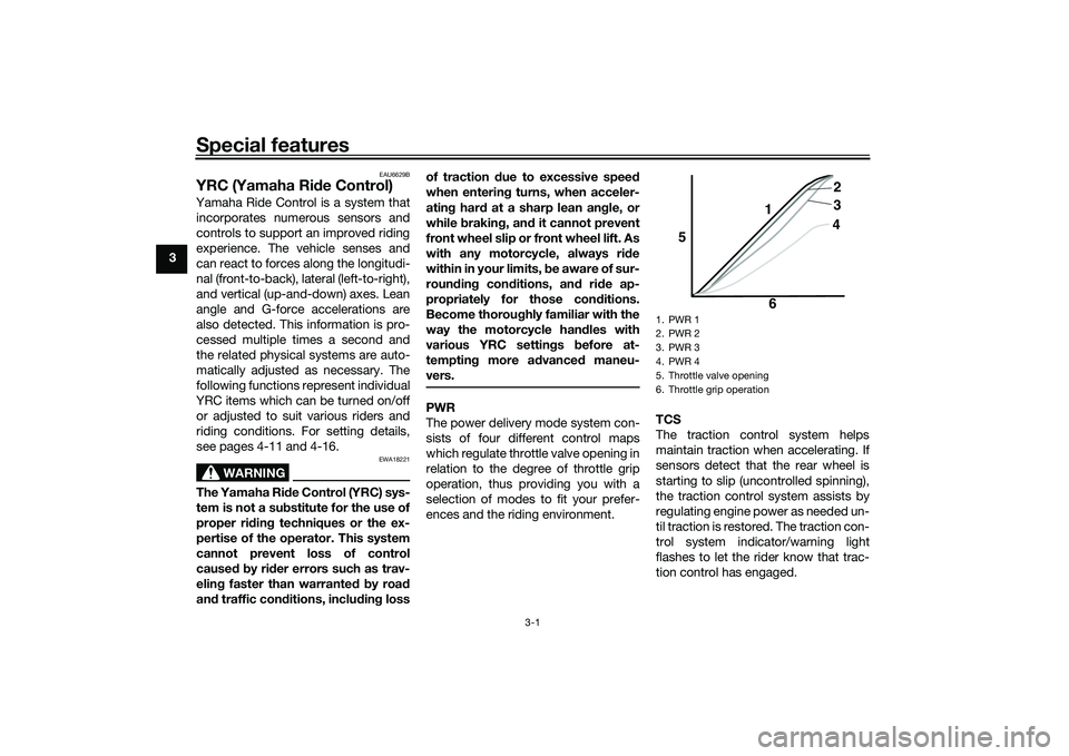
PWR
The power delivery mode system con-
sists of four different control maps
which regulate throttle valve opening in
relation to the degree of throttle grip
operation, thus providing you with a
selection of modes to fit your prefer-
ences and the riding environment. TCS
The traction control system helps
maintain traction when accelerating. If
sensors detect that the rear wheel is
starting to slip (uncontrolled spinning),
the traction control system assists by
regulating engine power as needed un-
til traction is restored. The traction con-
trol system indicator/warning light
flashes to let the rider know that trac-
tion control has engaged.
1. PWR 1
2. PWR 2
3. PWR 3
4. PWR 4
5. Throttle valve opening
6. Throttle grip operation
5
64
3 2
1
UB3LE0E0.book Page 1 Tuesday, July 23, 2019 12:05 PM
Page 19 of 136
Special features
3-2
3
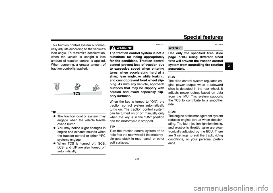
This traction control system automati-
cally adjusts according to the vehicle’s
lean angle. To maximize acceleration,
when the vehicle is upright a less
amount of traction control is applied.
When cornering, a greater amount of
traction control is applied.
TIP
The traction control system may
engage when the vehicle travels
over a bump.
You may notice slight changes in
engine and exhaust sounds when
the traction control or other YRC
systems engage.
When TCS is turned off, SCS,
LCS, and LIF are also turned off
automatically.
WARNING
EWA15433
The traction control system is not a
substitute for ri din g appropriately
for the con ditions. Traction control
cannot prevent loss of traction d ue
to excessive spee d when enterin g
turns, when acceleratin g har d at a
sharp lean an gle, or while brakin g,
an d cannot prevent front wheel slip-
pin g. As with any vehicle, approach
surfaces that may be slippery with
caution an d avoi d especially slip-
pery surfaces.When the key is turned to “ON”, the
traction control system automatically
turns on. The traction control system
can be turned on or off manually only
when the key is in the “ON” position
and the motorcycle is stopped.TIPTurn the traction control system off to
help free the rear wheel if the motorcy-
cle gets stuck in mud, sand, or other
soft surfaces.
NOTICE
ECA16801
Use only the specifie d tires. (See
pa ge 7-19.) Usin g different size d
tires will prevent the traction control
system from controllin g tire rotation
accurately.SCS
The slide control system regulates en-
gine power output when a sideward
slide is detected in the rear wheel. It
adjusts power output based on data
from the IMU. This system supports
the TCS to contribute to a smoother
ride.
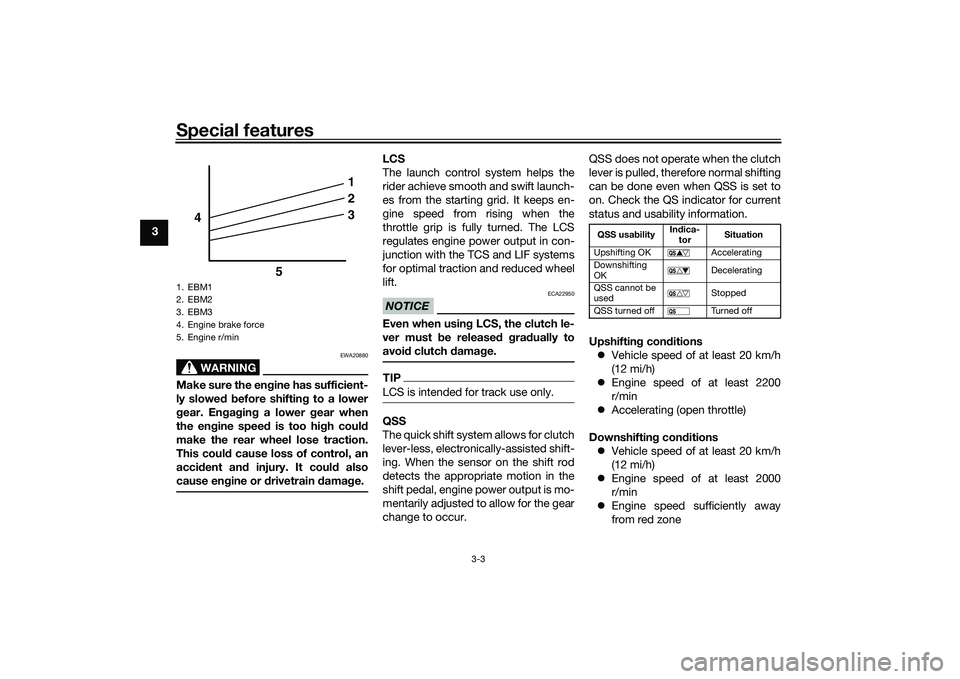
EBM
The engine brake management system
reduces engine torque when deceler-
ating. The fuel injection, ignition timing,
and electronic throttle valve are elec-
tronically adjusted by the ECU. There
are 3 settings to suit the track, riding
conditions, or your personal prefer-
ence.
TCS
UB3LE0E0.book Page 2 Tuesday, July 23, 2019 12:05 PM
Page 20 of 136
Special features
3-3
3
WARNING
EWA20880
Make sure the engine has sufficient-
ly slowe d b efore shiftin g to a lower
g ear. En gag in g a lower gear when
the en gine speed is too high coul d
make the rear wheel lose traction.
This coul d cause loss of control, an
acci dent an d injury. It coul d also
cause en gine or d rivetrain damag e.
LCS
The launch control system helps the
rider achieve smooth and swift launch-
es from the starting grid. It keeps en-
gine speed from rising when the
throttle grip is fully turned. The LCS
regulates engine power output in con-
junction with the TCS and LIF systems
for optimal traction and reduced wheel
lift.NOTICE
ECA22950
Even when usin g LCS, the clutch le-
ver must b e released g ra dually to
avoi d clutch damag e.TIPLCS is intended for track use only.QSS
The quick shift system allows for clutch
lever-less, electronically-assisted shift-
ing. When the sensor on the shift rod
detects the appropriate motion in the
shift pedal, engine power output is mo-
mentarily adjusted to allow for the gear
change to occur. QSS does not operate when the clutch
lever is pulled, therefore normal shifting
can be done even when QSS is set to
on. Check the QS indicator for current
status and usability information.
Upshiftin
g con ditions
Vehicle speed of at least 20 km/h
(12 mi/h)
Engine speed of at least 2200
r/min
Accelerating (open throttle)
Downshiftin g con ditions
Vehicle speed of at least 20 km/h
(12 mi/h)
Engine speed of at least 2000
r/min
Engine speed sufficiently away
from red zone
1. EBM1
2. EBM2
3. EBM3
4. Engine brake force
5. Engine r/min
1
2
3
4
5
QSS usability In
dica-
tor Situation
Upshifting OK Accelerating
Downshifting
OK Decelerating
QSS cannot be
used Stopped
QSS turned off Turned off
UB3LE0E0.book Page 3 Tuesday, July 23, 2019 12:05 PM
Page 21 of 136
Special features
3-4
3
Decelerating and throttle fully-
closed
TIPQS and QS can be individ-
ually set.
Shifting into or out of neutral must
be done using the clutch lever.LIF
The lift control system reduces the rate
at which the front wheel will continue to
rise during extreme acceleration, such
as during starts or out-of-corner exits.
When front-wheel lift is detected, en-
gine power is regulated to slow front-
wheel lift while still providing good ac-
celeration.
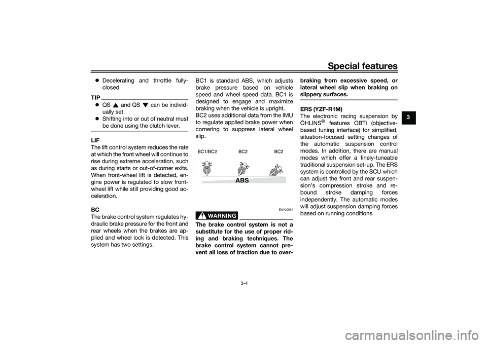
BC
The brake control system regulates hy-
draulic brake pressure for the front and
rear wheels when the brakes are ap-
plied and wheel lock is detected. This
system has two settings. BC1 is standard ABS, which adjusts
brake pressure based on vehicle
speed and wheel speed data. BC1 is
designed to engage and maximize
braking when the vehicle is upright.
BC2 uses additional data from the IMU
to regulate applied brake power when
cornering to suppress lateral wheel
slip.
WARNING
EWA20891
The
brake control system is not a
su bstitute for the use of proper ri d-
in g an d brakin g techniques. The
b rake control system cannot pre-
vent all loss of traction due to over- b
rakin g from excessive spee d, or
lateral wheel slip when brakin g on
slippery surfaces.
ERS (YZF-R1M)
The electronic racing suspension by
ÖHLINS
® features OBTi (objective-
based tuning interface) for simplified,
situation-focused setting changes of
the automatic suspension control
modes. In addition, there are manual
modes which offer a finely-tuneable
traditional suspension set-up. The ERS
system is controlled by the SCU which
can adjust the front and rear suspen-
sion’s compression stroke and re-
bound stroke damping forces
independently. The automatic modes
will adjust suspension damping forces
based on running conditions.
ABS
BC1/BC2 BC2 BC2
UB3LE0E0.book Page 4 Tuesday, July 23, 2019 12:05 PM
Page 22 of 136
Special features
3-5
3
EAU66313
GlossaryABS - Anti-lock Brake System
ABS ECU - Anti-lock Brake System
Electronic Control Unit
BC - Brake Control
CCU - Communication Control Unit
EBM - Engine Brake Management
ECU - Engine Control Unit
ERS - Electronic Racing Suspension
GPS - Global Positioning System
IMU - Inertial Measurement Unit
LCS - Launch Control System
LIF - Lift Control System
PWR - Power delivery mode
QS - Quick Shift
QSS - Quick Shift System
SC - Stability Control
SCS - Slide Control System
SCU - Suspension Control Unit
TCS - Traction Control System
YRC - Yamaha Ride ControlUB3LE0E0.book Page 5 Tuesday, July 23, 2019 12:05 PM
Page 28 of 136
Instrument and control functions
4-5
4 The LCS icon will flash and turn
white when the system has been
activated.
The traction control system can
only be turned off from the main
screen. Select TCS with the center
button, then push and hold the up
button until TCS OFF is displayed.
To turn the traction control system
back on, use the down button.
When TCS has been turned off,
the SCS, LCS, and LIF systems
are also turned off for all YRC
modes.
See “YRC Setting” on page 4-16
for more information on how to
customize YRC modes and adjust
YRC item setting levels.
EAU66100
Wheel switch “ ”
When the main screen is set to
STREET MODE, use the wheel switch
to scroll and reset the information dis-
play items.
When the main screen is set to TRACK
MODE, use the wheel switch to scroll
and reset the information display items
and to activate the lap timer. When the display has been changed to
the MENU screen, use the wheel
switch to navigate the setting modules
and make setting changes.
Operate the wheel switch as follows.
Rotate up
- rotate the wheel upward to
scroll up/left or increase a setting val-
ue.
Rotate down - rotate the wheel down-
ward to scroll down/right or decrease a
setting value.
Short push - briefly press the switch
inward to make and confirm selec-
tions.
Lon g push - press the switch inward
for one second to reset an information
display item or to access and exit the
MENU screen.
TIP See page 4-9 for more information
on the main screen and its func-
tions.
See page 4-15 for more informa-
tion on the MENU screen and how
to make setting changes.
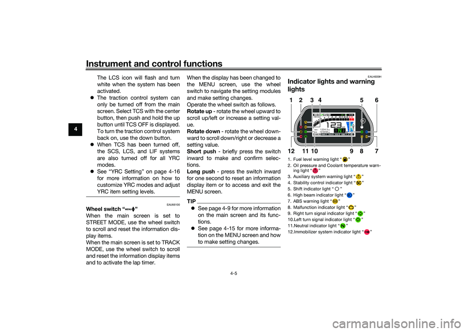
EAU4939H
Indicator li ghts an d warnin g
li g hts1. Fuel level warning light “ ”
2. Oil pressure and Coolant temperature warn-
ing light “ ”
3. Auxiliary system warning light “ ”
4. Stability control indicator light “ ”
5. Shift indicator light “ ”
6. High beam indicator light “ ”
7. ABS warning light “ ”
8. Malfunction indicator light “ ”
9. Right turn signal indicator light “ ”
10.Left turn signal indicator light “ ”
11.Neutral indicator light “ ”
12.Immobilizer system indicator light “ ”
ABS
1 2
GPSN
LCSQS
LIF 2
ODO123456 TRIP-1
1234.5
1000 r/min
km
km
km/h
10:
00
MODE-APWR 1TCS 3SCS 2EBM 1T-2
5
12
6
7
9
8
1012
11
3
4
UB3LE0E0.book Page 5 Tuesday, July 23, 2019 12:05 PM
Page 35 of 136
Instrument and control functions
4-12
4
MODE-D: street use or rainy weather
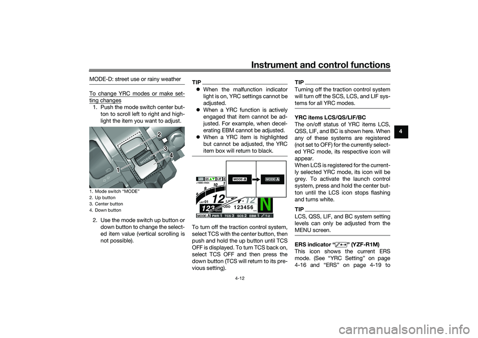
To change YRC modes or make set-ting changes1. Push the mode switch center but-
ton to scroll left to right and high-
light the item you want to adjust.
2. Use the mode switch up button or down button to change the select-
ed item value (vertical scrolling is
not possible).
TIPWhen the malfunction indicator
light is on, YRC settings cannot be
adjusted.
When a YRC function is actively
engaged that item cannot be ad-
justed. For example, when decel-
erating EBM cannot be adjusted.
When a YRC item is highlighted
but cannot be adjusted, the YRC
item box will return to black.To turn off the traction control system,
select TCS with the center button, then
push and hold the up button until TCS
OFF is displayed. To turn TCS back on,
select TCS OFF and then press the
down button (TCS will return to its pre-
vious setting).
TIPTurning off the traction control system
will turn off the SCS, LCS, and LIF sys-
tems for all YRC modes.YRC items LCS/QS/LIF/BC
The on/off status of YRC items LCS,
QSS, LIF, and BC is shown here. When
any of these systems are registered
(not set to OFF) for the currently select-
ed YRC mode, its respective icon will
appear.
When LCS is registered for the current-
ly selected YRC mode, its icon will be
grey. To activate the launch control
system, press and hold the center but-
ton until the LCS icon stops flashing
and turns white.TIPLCS, QSS, LIF, and BC system setting
levels can only be adjusted from the
MENU screen.ERS in dicator “ ” (YZF-R1M)
This icon shows the current ERS
mode. (See “YRC Setting” on page
4-16 and “ERS” on page 4-19 to
1. Mode switch “MODE”
2. Up button
3. Center button
4. Down button
1 2
3
4
N
12
12 34
LAP 01
ODO
km
123456
LATEST
1000 r/min
km/h
123
km/h
123
GEAR
GPS
LCS
QS
LIF
10 :
00
MODE-
APWR
1
TCS
3
SCS
2
EBM
1
T-2
2
MODE -
A
MODE-
A
UB3LE0E0.book Page 12 Tuesday, July 23, 2019 12:05 PM
Page 39 of 136
Instrument and control functions
4-16
4
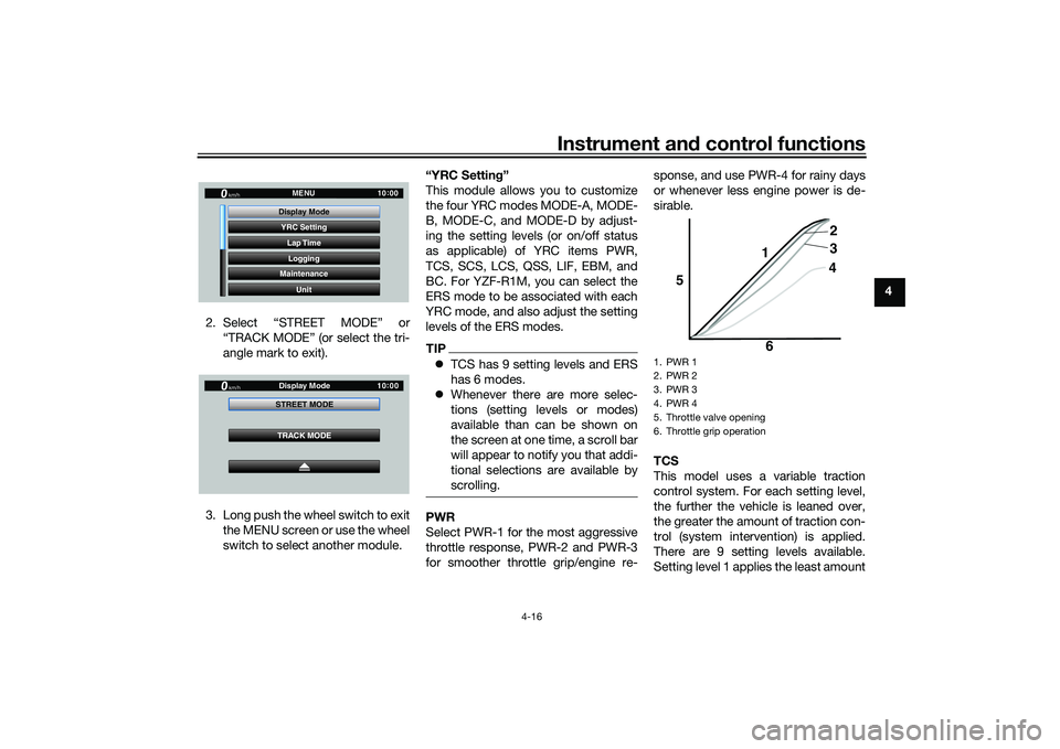
2. Select “STREET MODE” or “TRACK MODE” (or select the tri-
angle mark to exit).
3. Long push the wheel switch to exit the MENU screen or use the wheel
switch to select another module. “YRC Settin
g”
This module allows you to customize
the four YRC modes MODE-A, MODE-
B, MODE-C, and MODE-D by adjust-
ing the setting levels (or on/off status
as applicable) of YRC items PWR,
TCS, SCS, LCS, QSS, LIF, EBM, and
BC. For YZF-R1M, you can select the
ERS mode to be associated with each
YRC mode, and also adjust the setting
levels of the ERS modes.
TIP TCS has 9 setting levels and ERS
has 6 modes.
Whenever there are more selec-
tions (setting levels or modes)
available than can be shown on
the screen at one time, a scroll bar
will appear to notify you that addi-
tional selections are available by
scrolling.PWR
Select PWR-1 for the most aggressive
throttle response, PWR-2 and PWR-3
for smoother throttle grip/engine re- sponse, and use PWR-4 for rainy days
or whenever less engine power is de-
sirable.
TCS
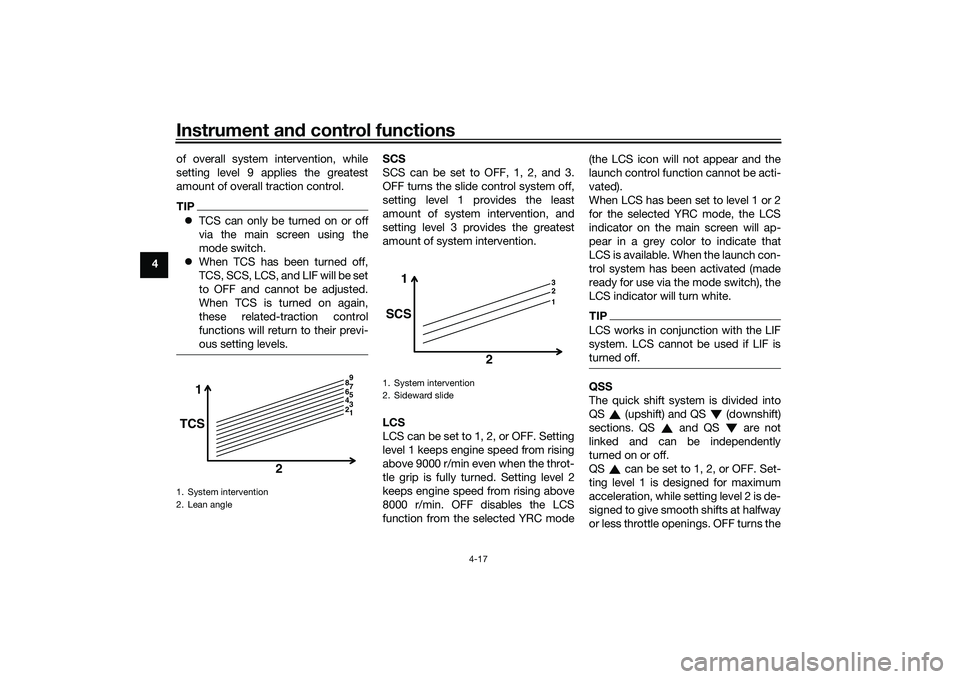
This model uses a variable traction
control system. For each setting level,
the further the vehicle is leaned over,
the greater the amount of traction con-
trol (system intervention) is applied.
There are 9 setting levels available.
Setting level 1 applies the least amount
YRC Setting
Lap TimeLogging
Maintenance
Unit
Display ModeMENU
km/h
GPS
10
:
00
km/h
10 :
00
TRACK MODE
STREET MODE
Display Mode
1. PWR 1
2. PWR 2
3. PWR 3
4. PWR 4
5. Throttle valve opening
6. Throttle grip operation
5
64
3 2
1
UB3LE0E0.book Page 16 Tuesday, July 23, 2019 12:05 PM
Page 40 of 136
Instrument and control functions
4-17
4 of overall system intervention, while
setting level 9 applies the greatest
amount of overall traction control.
TIP
TCS can only be turned on or off
via the main screen using the
mode switch.
When TCS has been turned off,
TCS, SCS, LCS, and LIF will be set
to OFF and cannot be adjusted.
When TCS is turned on again,
these related-traction control
functions will return to their previ-
ous setting levels.
SCS
SCS can be set to OFF, 1, 2, and 3.
OFF turns the slide control system off,
setting level 1 provides the least
amount of system intervention, and
setting level 3 provides the greatest
amount of system intervention.
LCS
LCS can be set to 1, 2, or OFF. Setting
level 1 keeps engine speed from rising
above 9000 r/min even when the throt-
tle grip is fully turned. Setting level 2
keeps engine speed from rising above
8000 r/min. OFF disables the LCS
function from the selected YRC mode (the LCS icon will not appear and the
launch control function cannot be acti-
vated).
When LCS has been set to level 1 or 2
for the selected YRC mode, the LCS
indicator on the main screen will ap-
pear in a grey color to indicate that
LCS is available. When the launch con-
trol system has been activated (made
ready for use via the mode switch), the
LCS indicator will turn white.
TIPLCS works in conjunction with the LIF
system. LCS cannot be used if LIF is
turned off.QSS
The quick shift system is divided into
QS (upshift) and QS (downshift)
sections. QS and QS are not
linked and can be independently
turned on or off.
QS can be set to 1, 2, or OFF. Set-
ting level 1 is designed for maximum
acceleration, while setting level 2 is de-
signed to give smooth shifts at halfway
or less throttle openings. OFF turns the
1. System intervention
2. Lean angle
1
TCS
2
1 5
4 3
2 6 9
8 7
1. System intervention
2. Sideward slide
1 3
2
1
SCS
2
UB3LE0E0.book Page 17 Tuesday, July 23, 2019 12:05 PM
Page 57 of 136
Instrument and control functions
4-34
4
The ABS performs best with
lon g b rakin g d istances.
On certain surfaces, such as
rou gh or g ravel roa ds, the b rak-
in g d istance may be lon ger with
the ABS than without.
BC2 incorporates standard ABS and in
addition regulates braking power when
cornering to suppress lateral wheel
slip.
WARNING
EWA20891
The brake control system is not a
su bstitute for the use of proper ri d-
in g an d brakin g techniques. The
b rake control system cannot pre-
vent all loss of traction due to over-
b rakin g from excessive spee d, or
lateral wheel slip when brakin g on
slippery surfaces.The ABS hydraulic unit is monitored by
the ABS ECU, which will revert the sys-
tem to conventional braking if a mal-
function occurs.
TIPThe ABS performs a self-diagnosis test
when the vehicle is started and reach-
es a speed of 10 km/h (6 mi/h). During
this test, a clicking noise may be audi-
ble from the hydraulic control unit, and
a vibration may be felt at the brake le-
ver or pedal, but this is normal.NOTICE
ECA20100
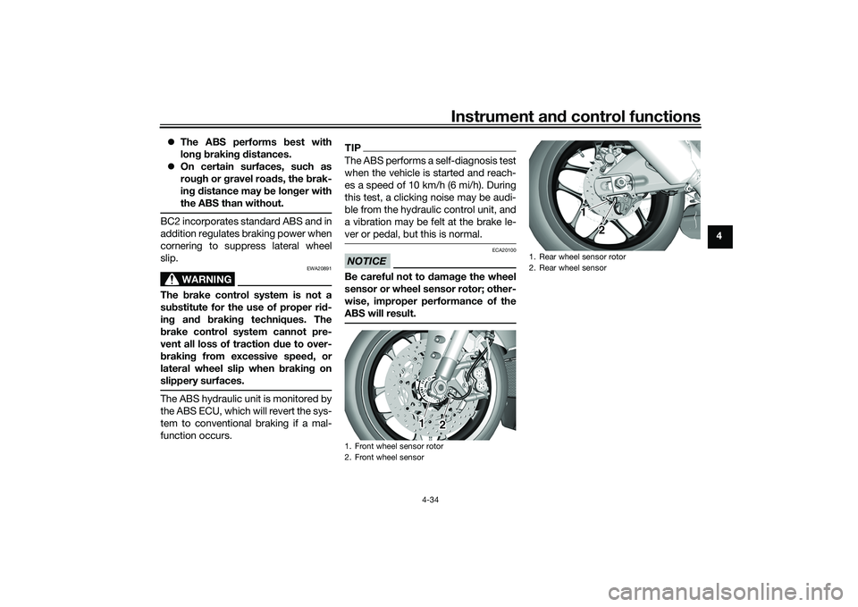
Be careful not to d amage the wheel
sensor or wheel sensor rotor; other-
wise, improper performance of the
ABS will result.1. Front wheel sensor rotor
2. Front wheel sensor
1
2
1. Rear wheel sensor rotor
2. Rear wheel sensor
1
2
UB3LE0E0.book Page 34 Tuesday, July 23, 2019 12:05 PM