clock YAMAHA YZF-R1M 2022 Owners Manual
[x] Cancel search | Manufacturer: YAMAHA, Model Year: 2022, Model line: YZF-R1M, Model: YAMAHA YZF-R1M 2022Pages: 136, PDF Size: 6.01 MB
Page 32 of 136
Instrument and control functions
4-9
4
If the en gine oil pressure is low,
the oil pressure warnin g icon
will come on. Check the oil level
(see pa ge 7-13).
If the warnin g li ght remains on
after lettin g the en gine cool an d
confirmin g the proper oil level,
have a Yamaha d ealer check
the vehicle. Do not continue to
operate the vehicle!
EAU88370
Auxiliary system warning light “ ”
This warning light comes on if a prob-
lem is detected in a non-engine-related
system.TIPWhen the vehicle is turned on, this light
should come on for a few seconds and
then go off. Otherwise, have a Yamaha
dealer check the vehicle.
EAU79286
DisplayThe display has two different main
screen display modes, STREET MODE
and TRACK MODE. Most of the func-
tions are viewable in either mode, but
the layout differs slightly. The following
items can be found on the display. Speedometer
Tachometer
Information display
Transmission gear display
Front brake pressure indicator
Acceleration indicator
YRC setting display MO-
DE/PWR/TCS/SCS/EBM
YRC setting display
LCS/QS/LIF/BC
ERS indicator (YZF-R1M)
GPS indicator (CCU-equipped
models)
Logging indicator (CCU-equipped
models)
Clock
Revolution peak hold indicator
Lap timer
Various warning icons
Error mode warning “Err”
TIPThis model uses a thin-film-transistor
liquid-crystal display (TFT LCD) for
good contrast and readability in vari-
ous lighting conditions. However, due
to the nature of this technology, it is
normal for a small number of pixels to
be inactive.
UB3LE1E0.book Page 9 Tuesday, August 10, 2021 2:28 PM
Page 33 of 136
Instrument and control functions
4-10
4
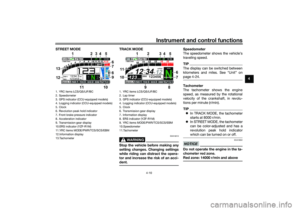
STREET MODE TRACK MODE
WARNING
EWA18210
Stop the vehicle
before makin g any
settin g chan ges. Chan gin g settin gs
while ri din g can distract the opera-
tor an d increase the risk of an acci-
d ent.
Speed ometer
The speedometer shows the vehicle’s
traveling speed.TIPThe display can be switched between
page 4-24.Tachometer
The tachometer shows the engine
speed, as measured by the rotational
velocity of the crankshaft, in revolu-
tions per minute (r/min).TIP In TRACK MODE, the tachometer
starts at 8000 r/min.
In STREET MODE, the tachometer
can be color-adjusted and has a
revolution peak hold indicator
which can be turned on or off.NOTICE
ECA10032
Do not operate the en gine in the ta-
chometer red zone.
Re d zone: 14000 r/min an d a bove
1. YRC items LCS/QS/LIF/BC
2. Speedometer
3. GPS indicator (CCU-equipped models)
4. Logging indicator (CCU-equipped models)
5. Clock
6. Revolution peak hold indicator
7. Front brake pressure indicator
8. Acceleration indicator
9. Transmission gear display
10.ERS indicator (YZF-R1M)
11.YRC items MODE/PWR/TCS/SCS/EBM
12.Information display
13.Tachometer
1
2
GPS
N
LCS
QS
LIF 2
ODO
123456
TRIP-1
1234.5
1000 r/min
km
km
km/h
10:
00
MODE-
APWR
1
TCS
3
SCS
2
EBM
1
T-2
6
11 978
3
1
10
25
4
13
12
1. YRC items LCS/QS/LIF/BC
2. Lap timer
3. GPS indicator (CCU-equipped modelsF
4. Logging indicator (CCU-equipped modelsF
5. Clock
6. Transmission gear display
7. Information display
8. ERS indicator (YZF-R1MF
9. YRC items MODE/PWR/TCS/SCS/EBM
10.Speedometer
11.Tachometer
N
12
12 34
LAP 01
ODO
km
123456
LATEST
1000 r/min
km/h
123
km/h
123
GEAR
GPS
LCS
QS
LIF
10
:
00
MODE-
APWR
1
TCS
3
SCS
2
EBM
1
T-2
29
1
8
1110
2
6
7
3
5
4
UB3LE1E0.book Page 10 Tuesday, August 10, 2021 2:28 PM
Page 36 of 136
Instrument and control functions
4-13
4
TIPTurning off the traction control system
will turn off the SCS, LCS, and LIF sys-
tems for all YRC modes.YRC items LCS/QS/LIF/BC
The on/off status of YRC items LCS,
QSS, LIF, and BC is shown here. When
any of these systems are registered
(not set to OFF) for the currently select-
ed YRC mode, its respective icon will
appear.
When LCS is registered for the current-
ly selected YRC mode, its icon will be
grey. To activate the launch control
system, press and hold the center but-
ton until the LCS icon stops flashing
and turns white.TIPLCS, QSS, LIF, and BC system setting
levels can only be adjusted from the
MENU screen.ERS in dicator “ ” (YZF-R1M)
This icon shows the current ERS mo-
de. (See “YRC Setting” on page 4-16
and “ERS” on page 4-20 to change the registered ERS mode or adjust ERS
setting levels.) If the ERS mode disap-
pears from the ERS indicator (the icon
turns blank), stop the vehicle and wait
a few seconds until the mode reap-
pears.
TIP
The suspension will remain fixed
at its most recent settings until
self-reset has completed.
If the ERS indicator does not re-
turn to normal, have a Yamaha
dealer inspect the vehicle.GPS in dicator “ ”
(CCU-equippe d mo dels)
This icon comes on when a GPS unit is
synched with your vehicle.
Lo ggin g in dicator “ ”
(CCU-equippe d mo dels)
This icon comes on when vehicle data
is being recorded via the logging func-
tion.
Clock
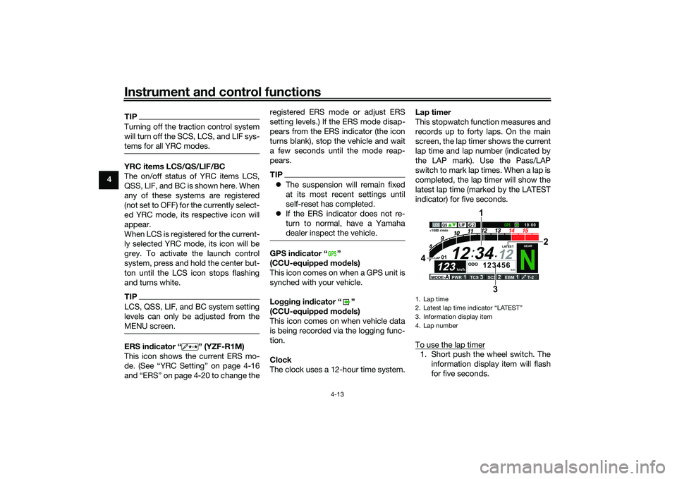
The clock uses a 12-hour time system. Lap timer
This stopwatch function measures and
records up to forty laps. On the main
screen, the lap timer shows the current
lap time and lap number (indicated by
the LAP mark). Use the Pass/LAP
switch to mark lap times. When a lap is
completed, the lap timer will show the
latest lap time (marked by the LATEST
indicator) for five seconds.
To use the lap timer
1. Short push the wheel switch. The
information display item will flash
for five seconds.
GPS
1. Lap time
2. Latest lap time indicator
Page 37 of 136
Instrument and control functions
4-14
4
2. While the information display item
is flashing, rotate the wheel switch
upward. The lap timer will flash for
five seconds.
3. While the lap timer is flashing, long push the wheel switch to activate
the lap timer or stop the lap timer.
4. When the lap timer has been acti- vated, press the Pass/LAP switch
to start the lap timer.
TIPThe engine must be running to use
the lap timer.
Set the information display to
FASTEST or AVERAGE for addi-
tional lap time information.
Accessing the MENU screen will
automatically stop the lap timer.
Whenever the lap timer is
stopped, the current lap will not be
recorded.
The lap time record can be viewed
and reset from the MENU screen.
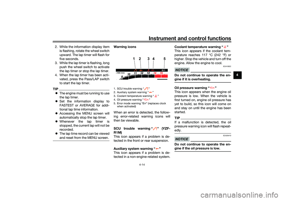
Warnin g icons
When an error is detected, the follow-
ing error-related warning icons will
then be viewable.
SCU trou ble warnin g“” (YZF-
R1M)
This icon appears if a problem is de-
tected in the front or rear suspension.
Auxiliary system warnin g“”
This icon appears if a problem is de-
tected in a non-engine-related system. Coolant temperature warnin
g“”
This icon appears if the coolant tem-
perature reaches 117 °C (242 °F) or
higher. Stop the vehicle and turn off the
engine. Allow the engine to cool.
NOTICE
ECA10022
Do not continue to operate the en-
g ine if it is overheatin g.Oil pressure warnin g“”
This icon appears when the engine oil
pressure is low. When the vehicle is
first turned on, engine oil pressure has
yet to build, so this icon will come on
and stay on until the engine has been
started.TIPIf a malfunction is detected, the oil
pressure warning icon will flash repeat-
edly.NOTICE
ECA26410
Do not continue to operate the en-
g ine if the oil pressure is low.
1. SCU trouble warning “ ”
2. Auxiliary system warning “ ”
3. Coolant temperature warning “ ”
4. Oil pressure warning “ ”
5. Error mode warning “Err” (replaces clock
when activated)1000 r/min
4
12
5
3
Er r
UB3LE1E0.book Page 14 Tuesday, August 10, 2021 2:28 PM
Page 38 of 136
Instrument and control functions
4-15
4 Error mo
de warnin g “Err”
When an internal error occurs (e.g.,
communication with a system control-
ler has been cut off), the error mode
warning will appear as follows.
“Err” and “ ” indicates an ECU error.
“Err” and “ ” indicates an SCU error.
“Err” only indicates an ABS ECU error.
TIPDepending on the nature of the error,
the display may not function properly
and YRC settings may be impossible
to change. Additionally, ABS may not
function properly. Use extra care when
braking and have a Yamaha dealer
check the vehicle immediately.
EAU7929B
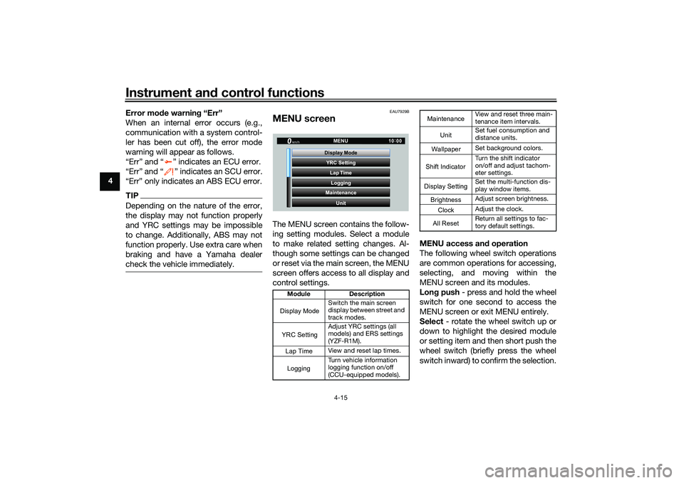
MENU screenThe MENU screen contains the follow-
ing setting modules. Select a module
to make related setting changes. Al-
though some settings can be changed
or reset via the main screen, the MENU
screen offers access to all display and
control settings. MENU access an
d operation
The following wheel switch operations
are common operations for accessing,
selecting, and moving within the
MENU screen and its modules.
Lon g push - press and hold the wheel
switch for one second to access the
MENU screen or exit MENU entirely.
Select - rotate the wheel switch up or
down to highlight the desired module
or setting item and then short push the
wheel switch (briefly press the wheel
switch inward) to confirm the selection.
Mo dule Description
Switch the main screen
display between street and
track modes.
Adjust YRC settings (all
models) and ERS settings
(YZF-R1M).
View and reset lap times.
Turn vehicle information
logging function on/off
(CCU-equipped models).
YRC Setting
Lap TimeLogging
Maintenance
Unit
Display ModeMENU
km/h
GPS
10
:
00
Display ModeYRC SettingLogging
View and reset three main-
tenance item intervals.
Set fuel consumption and
distance units.
Set background colors.
Turn the shift indicator
on/off and adjust tachom-
eter settings.
Set the multi-function dis-
play window items.
Adjust screen brightness.
Adjust the clock.
Return all settings to fac-
tory default settings.
Maintenance
Unit
WallpaperShift IndicatorDisplay SettingBrightnessClockAll Reset
UB3LE1E0.book Page 15 Tuesday, August 10, 2021 2:28 PM
Page 54 of 136

Instrument and control functions
4-31
4 To set the brightness
1. From the MENU screen, select
“Brightness”.
2. Select the desired brightness level by rotating the wheel switch, and
then short push the wheel switch
to fix the setting. “Clock”
This module allows you to set the
clock.
To set the clock
1. From the MENU screen, select
“Clock”.
2. When “Clock” is selected, the hours figure will be highlighted. 3. Set the hour by rotating and then
short push the wheel switch.
4. The minutes figure will become highlighted.
5. Set the minutes figure by rotating and then short push the wheel
switch.
GP GPS
Wallpaper Unit
Shift Indicator
Display Setting MENU
Maintenance
Brightness
km/h
10 :
00
Brightness
km/h
GPS
10 :
00
2
GP GPS
Shift Indicator Wallpaper
Display Setting Brightness MENU
Unit
Clock
km/h
10 :
00
Clock
km/h
10 :
00
11 :
34
Clock
km/h
10 :
00
10 :
34
Clock
km/h
10 :
00
10 34
:
UB3LE1E0.book Page 31 Tuesday, August 10, 2021 2:28 PM
Page 55 of 136
Instrument and control functions
4-32
4
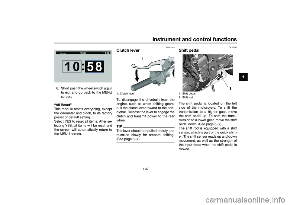
6. Short push the wheel switch again to exit and go back to the MENU
screen.
“All Reset”
This module resets everything, except
the odometer and clock, to its factory
preset or default setting.
Select YES to reset all items. After se-
lecting YES, all items will be reset and
the screen will automatically return to
the MENU screen.
EAU12823
Clutch leverTo disengage the drivetrain from the
engine, such as when shifting gears,
pull the clutch lever toward to the han-
dlebar. Release the lever to engage the
clutch and transmit power to the rear
wheel.TIPThe lever should be pulled rapidly and
released slowly for smooth shifting.
(See page 6-3.)
EAU83692
Shift pe dalThe shift pedal is located on the left
side of the motorcycle. To shift the
transmission to a higher gear, move
the shift pedal up. To shift the trans-
mission to a lower gear, move the shift
pedal down. (See page 6-3.)
The shift rod is equipped with a shift
sensor, which is part of the quick shift-
er. The shift sensor reads up and down
movement, as well as the strength of
the input force when the shift pedal is
moved.
Clock
km/h
10 :
00
10 :
58
1. Clutch lever
1
1. Shift pedal
2. Shift rod
1
2
UB3LE1E0.book Page 32 Tuesday, August 10, 2021 2:28 PM
Page 58 of 136

Instrument and control functions
4-35
4
EAU13077
Fuel tank capTo open the fuel tank cap
Open the fuel tank cap lock cover, in-
sert the key, and then turn it 1/4 turn
clockwise. The lock will be released
and the fuel tank cap can be opened.
To close the fuel tank cap
With the key still inserted, push down
the fuel tank cap. Turn the key 1/4 turn
counterclockwise, remove it, and then
close the lock cover.
TIPThe fuel tank cap cannot be closed un-
less the key is in the lock. In addition,
the key cannot be removed if the cap is
not properly closed and locked.
WARNING
EWA11092
Make sure that the fuel tank cap is
properly closed after filling fuel.
Leaking fuel is a fire hazard.
1. Rear wheel sensor rotor
2. Rear wheel sensor
12
1. Fuel tank cap lock cover
2. UnlockK
1
2
UB3LE1E0.book Page 35 Tuesday, August 10, 2021 2:28 PM
Page 61 of 136

Instrument and control functions
4-38
4
TIPSee page 7-13 for canister information.
EAU13435
Catalytic converterThe exhaust system contains catalytic
converter(s) to reduce harmful exhaust
emissions.
WARNING
EWA10863
The exhaust system is hot after op-
eration. To prevent a fire hazard or
burns: Do not park the vehicle near
possible fire hazards such as
grass or other materials that
easily burn.
Park the vehicle in a place
where pedestrians or children
are not likely to touch the hot
exhaust system.
Make sure that the exhaust sys-
tem has cooled down before
doing any maintenance work.
Do not allow the engine to idle
more than a few minutes. Long
idling can cause a build-up of
heat.
EAU79902
SeatsPassenger seat
To remove the passenger seat1. Insert the key into the seat lock,
and then turn it clockwise.
2. Lift the front of the passenger seat and pull it forward.
To install the passenger seat1. With the seat lock key still in the open position (turned clockwise),
insert the projection on the rear of
the passenger seat into the seat1. Seat lock
2. Unlock.
1
2
UB3LE1E0.book Page 38 Tuesday, August 10, 2021 2:28 PM
Page 115 of 136
![YAMAHA YZF-R1M 2022 Owners Manual Periodic maintenance and adjustment
7-34
7
switch off, then disconnect the
negative lead before discon-
necting the positive lead.
[ECA16304]
2. If the battery will be stored for
more than two months YAMAHA YZF-R1M 2022 Owners Manual Periodic maintenance and adjustment
7-34
7
switch off, then disconnect the
negative lead before discon-
necting the positive lead.
[ECA16304]
2. If the battery will be stored for
more than two months](/img/51/54067/w960_54067-114.png)
Periodic maintenance and adjustment
7-34
7
switch off, then disconnect the
negative lead before discon-
necting the positive lead.
[ECA16304]
2. If the battery will be stored for
more than two months, check it at
least once a month and fully char-
ge it if necessary.
3. Fully charge the battery before installation. NOTICE: When in-
stalling the battery, be sure to
turn the main switch off, then
connect the positive lead before
connecting the negative lead.
[ECA16842]
4. After installation, make sure that the battery leads are properly con-
nected to the battery terminals.NOTICE
ECA16531
Always keep the battery charged.
Storing a discharged battery can
cause permanent battery damage.
EAU66594
Replacing the fusesThe main fuse, the ABS motor fuse,
and fuse box 1 are located under the
rider seat. (See page 4-38.)
To access the main fuse and the ABS
motor fuse1. Remove the passenger seat andrider seat. (See page 4-38.)
2. Remove the battery cover by re- moving the bolts.
1. Main fuse
2. ABS motor fuse
3. Starter relay cover
4. ABS motor spare fuse
14
3
2
1. Fuse box 1
2. ABS solenoid fuse
3. Fuel injection system fuse
4. Electronic throttle valve fuse
5. Backup fuse (for clock and ECUF
6. Sub radiator fan motor fuse
7. Radiator fan motor fuse
8. Spare fuse
8 2
3
4
5
6
7
1
UB3LE1E0.book Page 34 Tuesday, August 10, 2021 2:28 PM