clock YAMAHA YZF-R3 2018 Owners Manual
[x] Cancel search | Manufacturer: YAMAHA, Model Year: 2018, Model line: YZF-R3, Model: YAMAHA YZF-R3 2018Pages: 100, PDF Size: 3.79 MB
Page 18 of 100

Instrument and control functions
3-4
3 b
rakin g. Have a Yamaha dealer
check the brake system an d electri-
cal circuits as soon as possi ble.
TIP
If the start switch is pushed while the
engine is running, the ABS warning
light will come on, but this is not a mal-
function.
EAU62470Shift timin g in dicator li ght
This indicator light can be set to come
on and go off at the desired engine
speeds and is used to inform the rider
when it is time to shift to the next high-
er gear. (See page 3-9 for a more de-
tailed explanation of this indicator light
and on how to set it.)
The electrical circuit of the indicator
light can be checked by turning the key
to “ ”. The indicator light should
come on for a few seconds, and then
go off.
If the indicator light does not come on
initially when the key is turned to “ ”,
or if the indicator light remains on, have
a Yamaha dealer check the electrical
circuit.
EAUN1470
Multi-function meter unit
WARNING
EWA12423
Be sure to stop the vehicle before
makin g any settin g chan ges to the
multi-function meter unit. Chang ing
settin gs while ri din g can d istract the
operator an d increase the risk of an
acci dent.
The multi-function meter unit is
equipped with the following:
a speedometer
a tachometer
a clock
a fuel meter
a coolant temperature meter
a transmission gear display
a multi-function display
a shift timing indicator light
1. “SEL” button
2. “RES” button
3. Tachometer
4. Fuel meter
5. Shift timing indicator light
6. Clock
7. Transmission gear display
8. Speedometer
9. Multi-function display
10.Coolant temperature meter
1091 3
246578
km/hkm/L
L/100kmMPH
mileMPG
UBR5E0E0.book Page 4 Wednesday, July 5, 2017 11:10 AM
Page 19 of 100

Instrument and control functions
3-5
3
Speed
ometer
The speedometer shows the vehicle’s
traveling speed.
TIP
For the UK: to switch the speedometer
and multi-function displays between
kilometers and miles, press the “SEL”
button for one second.
Tachometer
The tachometer allows the rider to
monitor the engine speed and keep it
within the ideal power range.
When the key is turned to “ ”, the ta-
chometer will sweep across the r/min
range and then return to zero r/min in
order to test the electrical circuit.
NOTICE
ECA10032
Do not operate the en gine in the ta-
chometer re d zone.
Re d zone: 12500 r/min an d a bove
Clock
The clock displays time in 12-hour for-
mat.
To set the clock
1. Turn the key to “ ”.
2. Push the “SEL” button and “RES”
button together for at least two
seconds.
3. When the hour digits start flash- ing, push the “RES” button to set
the hours.
4. Push the “SEL” button, and the minute digits will start flashing.
5. Push the “RES” button to set the minutes.
6. Push the “SEL” button and then release it to start the clock.
Fuel meter
1. Tachometer
2. Tachometer red zone
21
km/hkm/L
L/100kmMPH
mileMPG
1. Clock
1. Fuel meter
1
1
UBR5E0E0.book Page 5 Wednesday, July 5, 2017 11:10 AM
Page 29 of 100

Instrument and control functions
3-15
3
This ABS has a test mode which
allows the owner to experience
the pulsation at the brake lever or
brake pedal when the ABS is op-
erating. However, special tools are
required, so please consult your
Yamaha dealer.
NOTICE
ECA20100
Be careful not to damag e the wheel
sensor or wheel sensor rotor; other-
wise, improper performance of the
ABS will result.
EAU13075
Fuel tank cap
To open the fuel tank cap
Open the fuel tank cap lock cover, in-
sert the key into the lock, and then turn
it 1/4 turn clockwise. The lock will be
released and the fuel tank cap can be
opened.
To close the fuel tank cap 1. Push the fuel tank cap into posi- tion with the key inserted in the
lock.
2. Turn the key counterclockwise to the original position, remove it,
and then close the lock cover.
TIP
The fuel tank cap cannot be closed un-
less the key is in the lock. In addition,
the key cannot be removed if the cap is
not properly closed and locked.
WARNING
EWA11092
Make sure that the fuel tank cap is
properly close d after fillin g fuel.
Leakin g fuel is a fire hazar d.
1. Front wheel sensor
2. Front wheel sensor rotor
1. Rear wheel sensor
2. Rear wheel sensor rotor
1
2
1
2
1. Fuel tank cap lock cover
2. Unlock.
2 1
UBR5E0E0.book Page 15 Wednesday, July 5, 2017 11:10 AM
Page 32 of 100

Instrument and control functions
3-18
3
EAU13434
Catalytic converter
This model is equipped with a catalytic
converter in the exhaust system.
WARNING
EWA10863
The exhaust system is hot after op-
eration. To prevent a fire hazar d or
b urns:
Do not park the vehicle near
possi ble fire hazard s such as
g rass or other materials that
easily burn.
Park the vehicle in a place
where pe destrians or chil dren
are not likely to touch the hot
exhaust system.
Make sure that the exhaust sys-
tem has coole d down before
d oin g any maintenance work.
Do not allow the en gine to i dle
more than a few minutes. Lon g
i d lin g can cause a b uild-up of
heat.
NOTICE
ECA10702
Use only unlea ded g asoline. The use
of lead ed g asoline will cause unre-
pairab le dama ge to the catalytic
converter.
EAU62622
Seats
Passen ger seat
To remove the passenger seat
1. Insert the key into the seat lock, and then turn it clockwise.
2. While holding the key in that posi- tion, lift the rear of the passenger
seat and pull it backward.
To install the passenger seat
1. Insert the projections on the front of the passenger seat into the seat
holders as shown, and then push
the rear of the seat down to lock it
in place.
2. Remove the key.
1. Passenger seat lock
2. Unlock.
1. Projection
2. Seat holder
2 1
1
2
2
UBR5E0E0.book Page 18 Wednesday, July 5, 2017 11:10 AM
Page 77 of 100

Periodic maintenance an d a djustment
6-32
6
5. Place the tray in its original posi-
tion, and then install the quick fas-
teners.
6. Install the passenger seat.
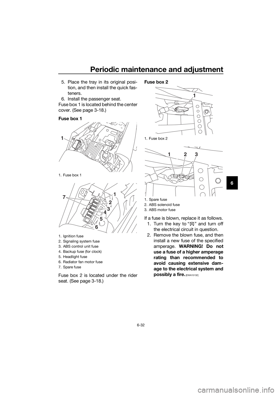
Fuse box 1 is located behind the center
cover. (See page 3-18.)
Fuse box 1
Fuse box 2 is located under the rider
seat. (See page 3-18.) Fuse
box 2
If a fuse is blown, replace it as follows. 1. Turn the key to “ ” and turn off the electrical circuit in question.
2. Remove the blown fuse, and then install a new fuse of the specified
amperage. WARNING! Do not
use a fuse of a hi gher ampera ge
ratin g than recommen ded to
avoi d causin g extensive dam-
a g e to the electrical system an d
possi bly a fire.
[EWA15132]
1. Fuse box 1
1. Ignition fuse
2. Signaling system fuse
3. ABS control unit fuse
4. Backup fuse (for clock)
5. Headlight fuse
6. Radiator fan motor fuse
7. Spare fuse
1
71
2
3
5
6
4
1. Fuse box 2
1. Spare fuse
2. ABS solenoid fuse
3. ABS motor fuse
1
123
UBR5E0E0.book Page 32 Wednesday, July 5, 2017 11:10 AM
Page 78 of 100

Periodic maintenance an d a djustment
6-33
6 3. Turn the key to “ ” and turn on
the electrical circuit in question to
check if the device operates.
4. If the fuse immediately blows again, have a Yamaha dealer
check the electrical system.
EAU39014
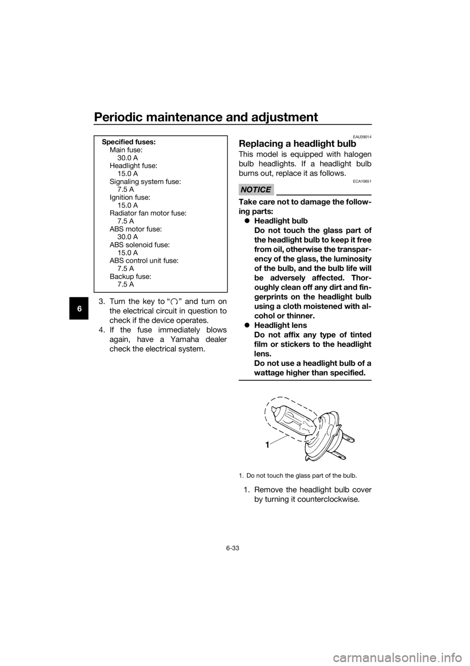
Replacin g a hea dlig ht bul b
This model is equipped with halogen
bulb headlights. If a headlight bulb
burns out, replace it as follows.
NOTICE
ECA10651
Take care not to damag e the follow-
in g parts:
Hea dlig ht bul b
Do not touch the glass part of
the hea dlig ht bul b to keep it free
from oil, otherwise the transpar-
ency of the glass, the luminosity
of the b ulb, an d the bul b life will
b e ad versely affected . Thor-
ou ghly clean off any d irt and fin-
g erprints on the hea dlig ht bul b
usin g a cloth moistene d with al-
cohol or thinner.
Hea dlig ht lens
Do not affix any type of tinted
film or stickers to the head light
lens.
Do not use a hea dlig ht bul b of a
watta ge hi gher than specifie d.
1. Remove the headlight bulb cover
by turning it counterclockwise.
Specifie d fuses:
Main fuse: 30.0 A
Headlight fuse:
15.0 A
Signaling system fuse: 7.5 A
Ignition fuse: 15.0 A
Radiator fan motor fuse:
7.5 A
ABS motor fuse: 30.0 A
ABS solenoid fuse: 15.0 A
ABS control unit fuse:
7.5 A
Backup fuse: 7.5 A
1. Do not touch the glass part of the bulb.
UBR5E0E0.book Page 33 Wednesday, July 5, 2017 11:10 AM
Page 79 of 100

Periodic maintenance an d a djustment
6-34
6
2. Disconnect the headlight coupler.
3. Unhook the headlight bulb holder,
and then remove the burnt-out
bulb.
4. Place a new headlight bulb into position, and then secure it with
the bulb holder.
5. Connect the headlight coupler.
6. Install the headlight bulb cover by turning it clockwise. 7. Have a Yamaha dealer adjust the
headlight beam if necessary.
1. Headlight bulb cover
1. Headlight coupler
1. Headlight bulb holder
1
1
1
UBR5E0E0.book Page 34 Wednesday, July 5, 2017 11:10 AM
Page 81 of 100

Periodic maintenance an d a djustment
6-36
6
EAU62590
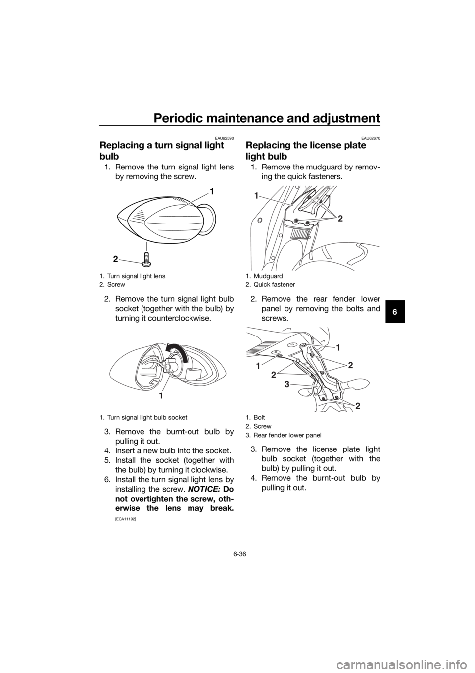
Replacin g a turn si gnal li ght
b ul b
1. Remove the turn signal light lens
by removing the screw.
2. Remove the turn signal light bulb socket (together with the bulb) by
turning it counterclockwise.
3. Remove the burnt-out bulb by pulling it out.
4. Insert a new bulb into the socket.
5. Install the socket (together with the bulb) by turning it clockwise.
6. Install the turn signal light lens by installing the screw. NOTICE: Do
not overti ghten the screw, oth-
erwise the lens may break.
[ECA11192] EAU62670
Replacin
g the license plate
lig ht bul b
1. Remove the mudguard by remov-
ing the quick fasteners.
2. Remove the rear fender lower panel by removing the bolts and
screws.
3. Remove the license plate light bulb socket (together with the
bulb) by pulling it out.
4. Remove the burnt-out bulb by pulling it out.
1. Turn signal light lens
2. Screw
1. Turn signal light bulb socket
1
2
1
1. Mudguard
2. Quick fastener
1. Bolt
2. Screw
3. Rear fender lower panel
1
2
3
2
1
2
2
1
UBR5E0E0.book Page 36 Wednesday, July 5, 2017 11:10 AM
Page 85 of 100

Periodic maintenance an d a djustment
6-40
6
En
gine overheatin g
WARNING
EWAT1041
Do not remove the rad iator cap when the engine an d ra diator are hot.
Scal din g hot flui d an d steam may b e blown out un der pressure, which
coul d cause serious injury. Be sure to wait until the en gine has coole d.
Place a thick ra g, like a towel, over the rad iator cap, and then slowly ro-
tate the cap counterclockwise to the d etent to allow any residual pres-
sure to escape. When the hissin g soun d has stoppe d, press d own on the
cap while turnin g it counterclockwise, an d then remove the cap.
TIP
If coolant is not available, tap water can be temporarily used instead, provided
that it is changed to the recommended coolant as soon as possible.
Wait until the engine
has cooled.
Check the coolant
level in the reservoir
and radiator.Add coolant.
(See TIP.)
The coolant level is
OK.
There is no leakage.
There is leakage.
The coolant level is
low.
Check the cooling
system for leakage.
Have a Yamaha
dealer check and
repair the cooling
system.
Start the engine. If the engine overheats again,
have a Yamaha dealer check and repair the cooling
system.
UBR5E0E0.book Page 40 Wednesday, July 5, 2017 11:10 AM