headlight YAMAHA YZF-R3 2018 Owners Manual
[x] Cancel search | Manufacturer: YAMAHA, Model Year: 2018, Model line: YZF-R3, Model: YAMAHA YZF-R3 2018Pages: 100, PDF Size: 3.79 MB
Page 5 of 100

Table of contents
Safety information ............................1-1
Description ........................................2-1
Left view ..........................................2-1
Right view........................................2-2
Controls and instruments ................2-3
Instrument an d control functions ....3-1
Main switch/steering lock ...............3-1
Indicator lights and warning lights ............................................3-2
Multi-function meter unit .................3-4
Handlebar switches.......................3-11
Clutch lever ...................................3-12
Shift pedal .....................................3-13
Brake lever ....................................3-13
Brake pedal ...................................3-14
ABS ...............................................3-14
Fuel tank cap.................................3-15
Fuel................................................3-16
Fuel tank overflow hose ................3-17
Catalytic converter ........................3-18
Seats .............................................3-18
Helmet holders ..............................3-20
Storage compartment ...................3-21
Rear view mirrors ..........................3-21
Adjusting the shock absorber assembly....................................3-22
Luggage strap holders ..................3-23
Sidestand ......................................3-23
Ignition circuit cut-off system........3-24
For your safety – pre-operation
checks ...............................................4-1
Operation an d important ri din g
points .................................................5-1
Starting the engine ..........................5-2
Shifting ............................................5-3
Engine break-in ...............................5-4
Parking ............................................5-4
Perio dic maintenance an d
a d justment ........................................6-1
Owner’s tool kit ...............................6-2 Periodic maintenance chart for
the emission control system........ 6-3
General maintenance and lubrication chart........................... 6-4
Checking the spark plugs ............... 6-7
Canister........................................... 6-8
Engine oil and oil filter cartridge ..... 6-8
Coolant ......................................... 6-11
Replacing the air filter element
and cleaning the check hose..... 6-13
Checking the throttle grip free
play ............................................ 6-15
Valve clearance ............................. 6-15
Tires .............................................. 6-16
Cast wheels .................................. 6-18
Adjusting the clutch lever free play ..................................... 6-18
Checking the brake lever free play ..................................... 6-20
Brake light switches ...................... 6-20
Checking the front and rear
brake pads................................. 6-21
Checking the brake fluid level....... 6-22
Changing the brake fluid............... 6-23
Drive chain slack ........................... 6-23
Cleaning and lubricating the
drive chain ................................. 6-25
Checking and lubricating the cables ........................................ 6-25
Checking and lubricating the throttle grip and cable ............... 6-26
Checking and lubricating the
brake and shift pedals ............... 6-26
Checking and lubricating the brake and clutch levers ............. 6-27
Checking and lubricating the sidestand ................................... 6-27
Lubricating the swingarm pivots... 6-28
Checking the front fork ................. 6-28
Checking the steering ................... 6-29
Checking the wheel bearings ....... 6-29
Battery .......................................... 6-30
Replacing the fuses ...................... 6-31
Replacing a headlight bulb ........... 6-33
Auxiliary light bulb......................... 6-35
Tail/brake light .............................. 6-35
UBR5E0E0.book Page 1 Wednesday, July 5, 2017 11:10 AM
Page 13 of 100
Description
2-2
2
EAU63391
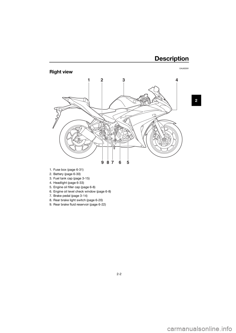
Right view
4
9
123
8765
1. Fuse box (page 6-31)
2. Battery (page 6-30)
3. Fuel tank cap (page 3-15)
4. Headlight (page 6-33)
5. Engine oil filler cap (page 6-8)
6. Engine oil level check window (page 6-8)
7. Brake pedal (page 3-14)
8. Rear brake light switch (page 6-20)
9. Rear brake fluid reservoir (page 6-22)
UBR5E0E0.book Page 2 Wednesday, July 5, 2017 11:10 AM
Page 15 of 100

Instrument and control functions
3-1
3
EAU10462
Main switch/steerin g lock
The main switch/steering lock controls
the ignition and lighting systems, and is
used to lock the steering. The various
positions are described below.
EAU62480 (on)
All electrical circuits are supplied with
power; the meter lighting, taillight, li-
cense plate light and auxiliary light
come on, and the engine can be start-
ed. The key cannot be removed.
TIP
The headlight comes on automatically
when the engine is started and stays
on until the key is turned to “ ”, even
if the engine stalls.
EAU54301 (off)
All electrical systems are off. The key
can be removed.
WARNING
EWA16371
Never turn the key to “ ” or “LOCK”
while the vehicle is movin g. Other-
wise the electrical systems will be
switched off, which may result in
loss of control or an acci dent.
EAU60863LOCK
The steering is locked and all electrical
systems are off. The key can be re-
moved.
To lock the steering
1. Turn the handlebars all the way to
the left.
2. With the key in the “ ” position, push the key in and turn it to
“LOCK”.
3. Remove the key.
TIP
If the steering will not lock, try turning
the handlebars back to the right slight-
ly.
To unlock the steering
ON
OFF
LOCK
1. Push.
2. Turn.
1. Push.
2. Turn.
12
12
UBR5E0E0.book Page 1 Wednesday, July 5, 2017 11:10 AM
Page 16 of 100
Instrument and control functions
3-2
3 From the “LOCK” position, push the
key and turn it to “ ”.
EAU4939C
In
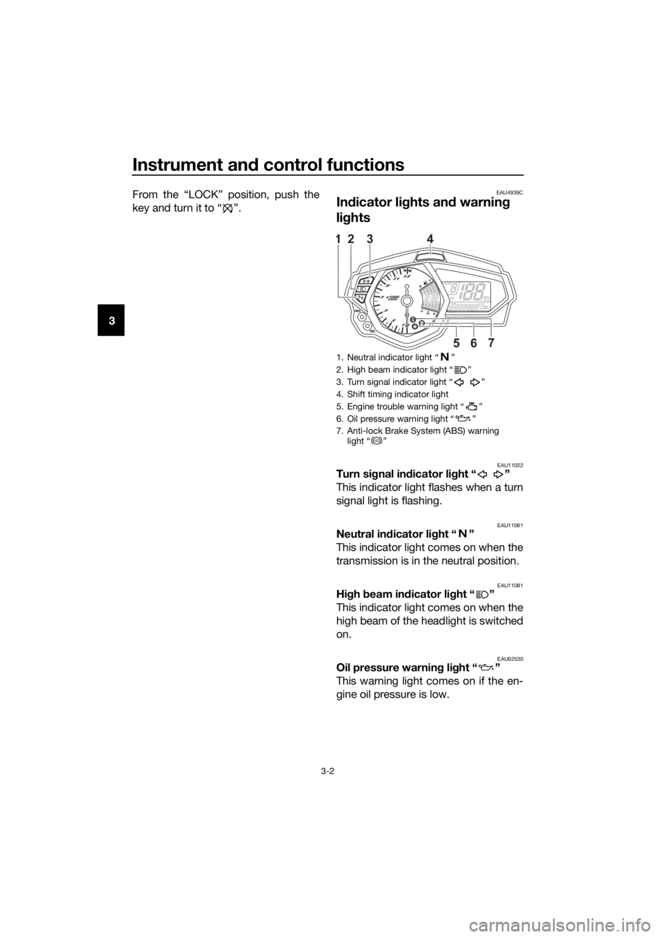
dicator li ghts an d warnin g
li g hts
EAU11022Turn si gnal in dicator li ght “ ”
This indicator light flashes when a turn
signal light is flashing.
EAU11061Neutral in dicator li ght “ ”
This indicator light comes on when the
transmission is in the neutral position.
EAU11081Hi gh beam in dicator li ght “ ”
This indicator light comes on when the
high beam of the headlight is switched
on.
EAU62530Oil pressure warning light “ ”
This warning light comes on if the en-
gine oil pressure is low.
1. Neutral indicator light “ ”
2. High beam indicator light “ ”
3. Turn signal indicator light “ ”
4. Shift timing indicator light
5. Engine trouble warning light “ ”
6. Oil pressure warning light “ ”
7. Anti-lock Brake System (ABS) warning light “ ”
56
3124
km/hkm/L
L/100km
7
MPHmileMPG
ABS
UBR5E0E0.book Page 2 Wednesday, July 5, 2017 11:10 AM
Page 25 of 100
Instrument and control functions
3-11
3
2. Push the “SEL” button to confirm
the selected brightness level. The
display exits the shift timing light
control mode and returns to the
standard multi-function display
mode.
EAU1234M
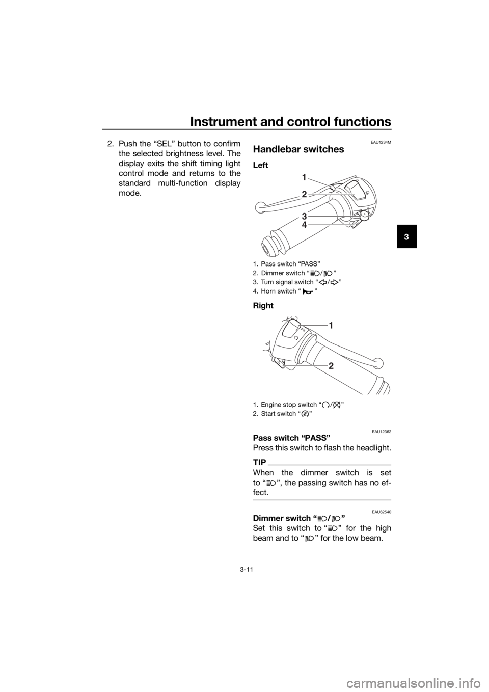
Han dle bar switches
Left
Ri ght
EAU12362Pass switch “PASS”
Press this switch to flash the headlight.
TIP
When the dimmer switch is set
to “ ”, the passing switch has no ef-
fect.
EAU62540Dimmer switch “ / ”
Set this switch to “ ” for the high
beam and to “ ” for the low beam.
1. Pass switch “PASS”
2. Dimmer switch “ / ”
3. Turn signal switch “ / ”
4. Horn switch “ ”
1. Engine stop switch “ / ”
2. Start switch “ ”
4
3
1
2
2
1
UBR5E0E0.book Page 11 Wednesday, July 5, 2017 11:10 AM
Page 26 of 100
Instrument and control functions
3-12
3
TIP
When the switch is set to low beam,
only the right headlight bulb comes on.
When the switch is set to high beam,
both headlight bulbs come on.
EAU12461Turn si gnal switch “ / ”
To signal a right-hand turn, push this
switch to “ ”. To signal a left-hand
turn, push this switch to “ ”. When
released, the switch returns to the cen-
ter position. To cancel the turn signal
lights, push the switch in after it has re-
turned to the center position.
EAU12501Horn switch “ ”
Press this switch to sound the horn.
EAU12662En gine stop switch “ / ”
Set this switch to “ ” before starting
the engine. Set this switch to “ ” to
stop the engine in case of an emergen-
cy, such as when the vehicle overturns
or when the throttle cable is stuck.
EAU12713Start switch “ ”
Push this switch to crank the engine
with the starter. See page 5-2 for start-
ing instructions prior to starting the en-
gine.
EAU62500The engine trouble warning light will
come on when the key is turned to “ ”
and the start switch is pushed, but this
does not indicate a malfunction.
EAU12822
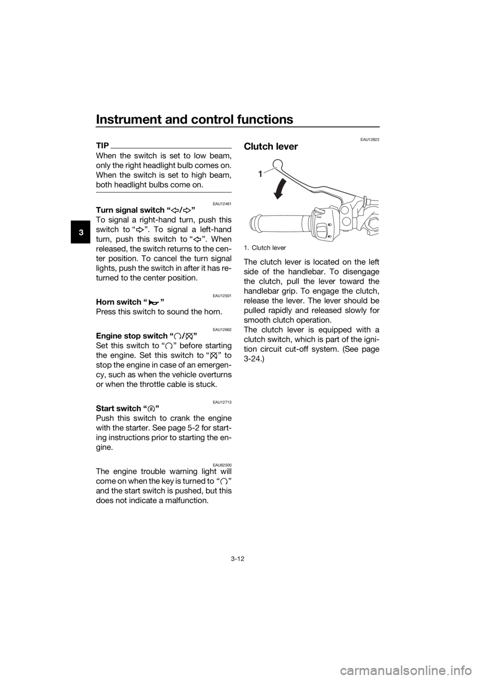
Clutch lever
The clutch lever is located on the left
side of the handlebar. To disengage
the clutch, pull the lever toward the
handlebar grip. To engage the clutch,
release the lever. The lever should be
pulled rapidly and released slowly for
smooth clutch operation.
The clutch lever is equipped with a
clutch switch, which is part of the igni-
tion circuit cut-off system. (See page
3-24.)
1. Clutch lever
1
UBR5E0E0.book Page 12 Wednesday, July 5, 2017 11:10 AM
Page 51 of 100

Periodic maintenance an d a djustment
6-6
6
EAU72800
TIP
Air filter
• This model’s air filter is equipped with a disposable oil-coated paper ele- ment, which must not be cleaned with compressed air to avoid damaging
it.
• The air filter element needs to be replaced more frequently when riding in unusually wet or dusty areas.
Hydraulic brake service
• Regularly check and, if necessary, correct the brake fluid level.
• Every two years replace the internal components of the brake master cyl- inders and calipers, and change the brake fluid.
• Replace the brake hoses every four years and if cracked or damaged.
28 *Movin
g parts an d
cab les • Lubricate.
√√√√√
29 *Throttle
grip hous-
in g an d cab le • Check operation and free play.
• Adjust the throttle cable free
play if necessary.
• Lubricate the throttle grip hous- ing and cable. √√√√√
30 *Li
ghts, si gnals an d
switches • Check operation.
• Adjust headlight beam.
√√√√√√
NO. ITEM
X 1000 km
CHECK OR
MAINTENANCE JOB
X 1000 mi
ODOMETER READINGS
ANNUAL CHECK
110203040
0.66121824
UBR5E0E0.book Page 6 Wednesday, July 5, 2017 11:10 AM
Page 77 of 100
Periodic maintenance an d a djustment
6-32
6
5. Place the tray in its original posi-
tion, and then install the quick fas-
teners.
6. Install the passenger seat.
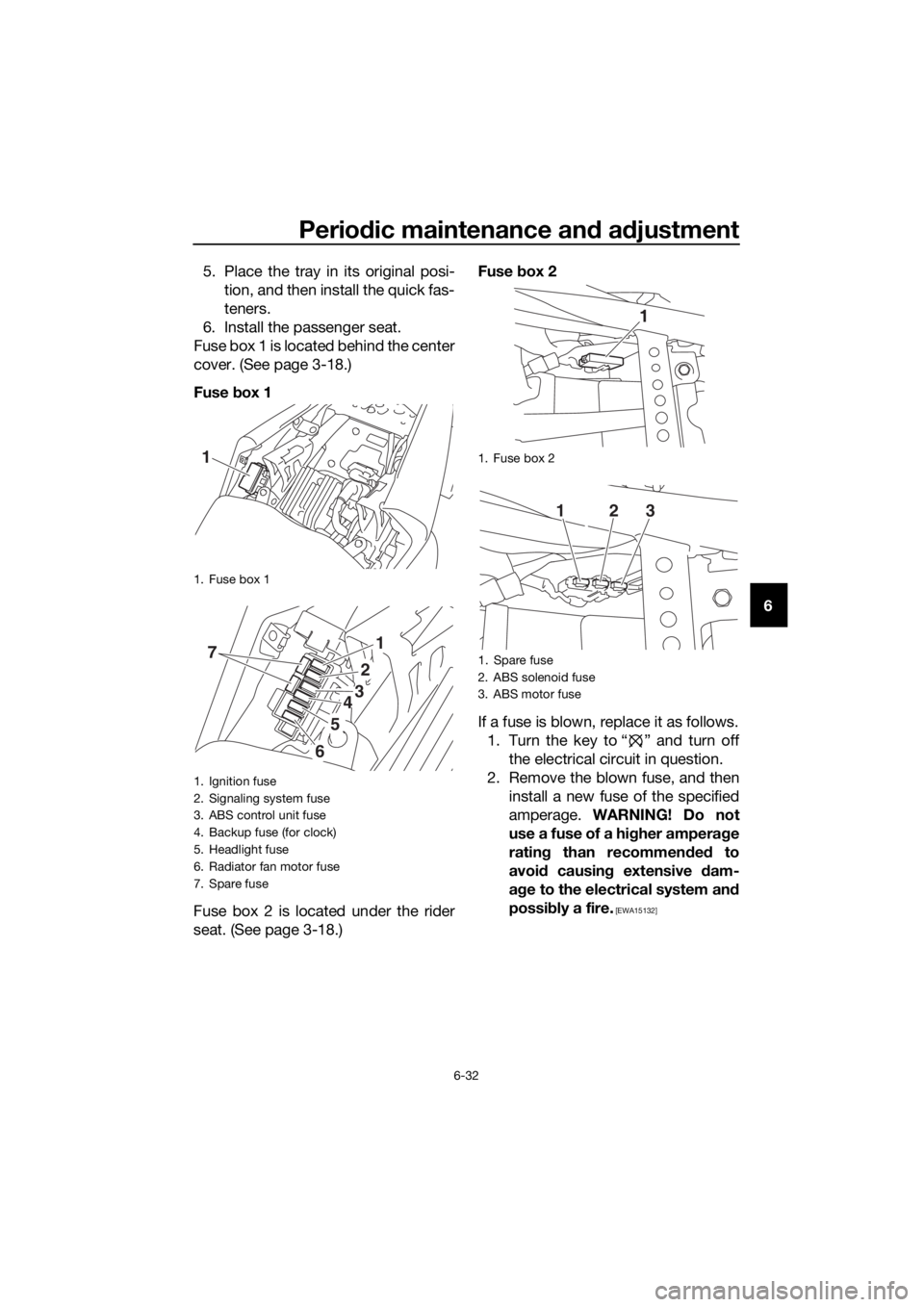
Fuse box 1 is located behind the center
cover. (See page 3-18.)
Fuse box 1
Fuse box 2 is located under the rider
seat. (See page 3-18.) Fuse
box 2
If a fuse is blown, replace it as follows. 1. Turn the key to “ ” and turn off the electrical circuit in question.
2. Remove the blown fuse, and then install a new fuse of the specified
amperage. WARNING! Do not
use a fuse of a hi gher ampera ge
ratin g than recommen ded to
avoi d causin g extensive dam-
a g e to the electrical system an d
possi bly a fire.
[EWA15132]
1. Fuse box 1
1. Ignition fuse
2. Signaling system fuse
3. ABS control unit fuse
4. Backup fuse (for clock)
5. Headlight fuse
6. Radiator fan motor fuse
7. Spare fuse
1
71
2
3
5
6
4
1. Fuse box 2
1. Spare fuse
2. ABS solenoid fuse
3. ABS motor fuse
1
123
UBR5E0E0.book Page 32 Wednesday, July 5, 2017 11:10 AM
Page 78 of 100
Periodic maintenance an d a djustment
6-33
6 3. Turn the key to “ ” and turn on
the electrical circuit in question to
check if the device operates.
4. If the fuse immediately blows again, have a Yamaha dealer
check the electrical system.
EAU39014
Replacin g a hea dlig ht bul b
This model is equipped with halogen
bulb headlights. If a headlight bulb
burns out, replace it as follows.
NOTICE
ECA10651
Take care not to damag e the follow-
in g parts:
Hea dlig ht bul b
Do not touch the glass part of
the hea dlig ht bul b to keep it free
from oil, otherwise the transpar-
ency of the glass, the luminosity
of the b ulb, an d the bul b life will
b e ad versely affected . Thor-
ou ghly clean off any d irt and fin-
g erprints on the hea dlig ht bul b
usin g a cloth moistene d with al-
cohol or thinner.
Hea dlig ht lens
Do not affix any type of tinted
film or stickers to the head light
lens.
Do not use a hea dlig ht bul b of a
watta ge hi gher than specifie d.
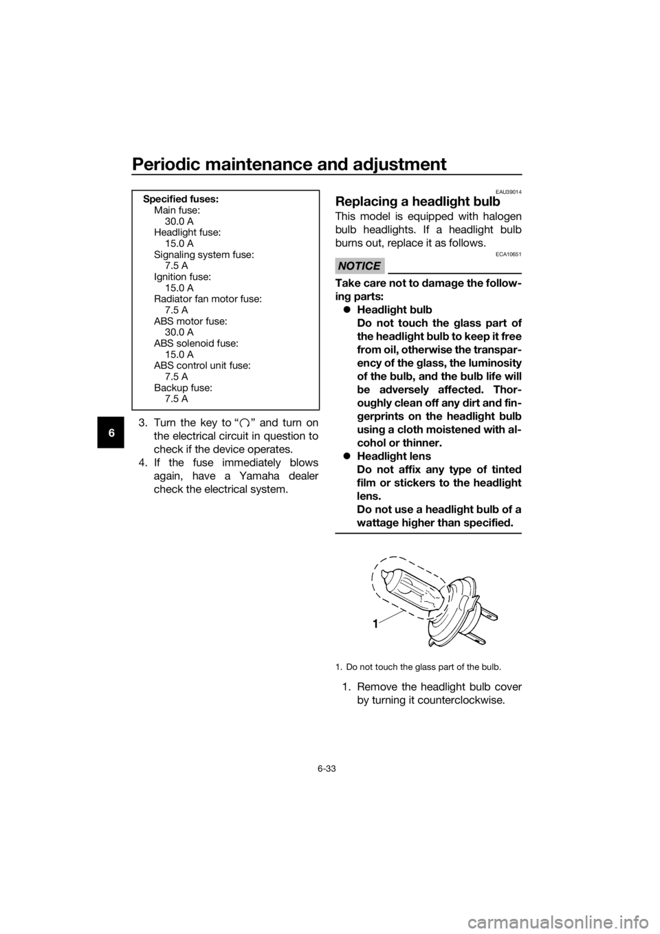
1. Remove the headlight bulb cover
by turning it counterclockwise.
Specifie d fuses:
Main fuse: 30.0 A
Headlight fuse:
15.0 A
Signaling system fuse: 7.5 A
Ignition fuse: 15.0 A
Radiator fan motor fuse:
7.5 A
ABS motor fuse: 30.0 A
ABS solenoid fuse: 15.0 A
ABS control unit fuse:
7.5 A
Backup fuse: 7.5 A
1. Do not touch the glass part of the bulb.
UBR5E0E0.book Page 33 Wednesday, July 5, 2017 11:10 AM
Page 79 of 100

Periodic maintenance an d a djustment
6-34
6
2. Disconnect the headlight coupler.
3. Unhook the headlight bulb holder,
and then remove the burnt-out
bulb.
4. Place a new headlight bulb into position, and then secure it with
the bulb holder.
5. Connect the headlight coupler.
6. Install the headlight bulb cover by turning it clockwise. 7. Have a Yamaha dealer adjust the
headlight beam if necessary.
1. Headlight bulb cover
1. Headlight coupler
1. Headlight bulb holder
1
1
1
UBR5E0E0.book Page 34 Wednesday, July 5, 2017 11:10 AM