alarm YAMAHA YZF-R6 2001 Owners Manual
[x] Cancel search | Manufacturer: YAMAHA, Model Year: 2001, Model line: YZF-R6, Model: YAMAHA YZF-R6 2001Pages: 118, PDF Size: 12.83 MB
Page 15 of 118

3
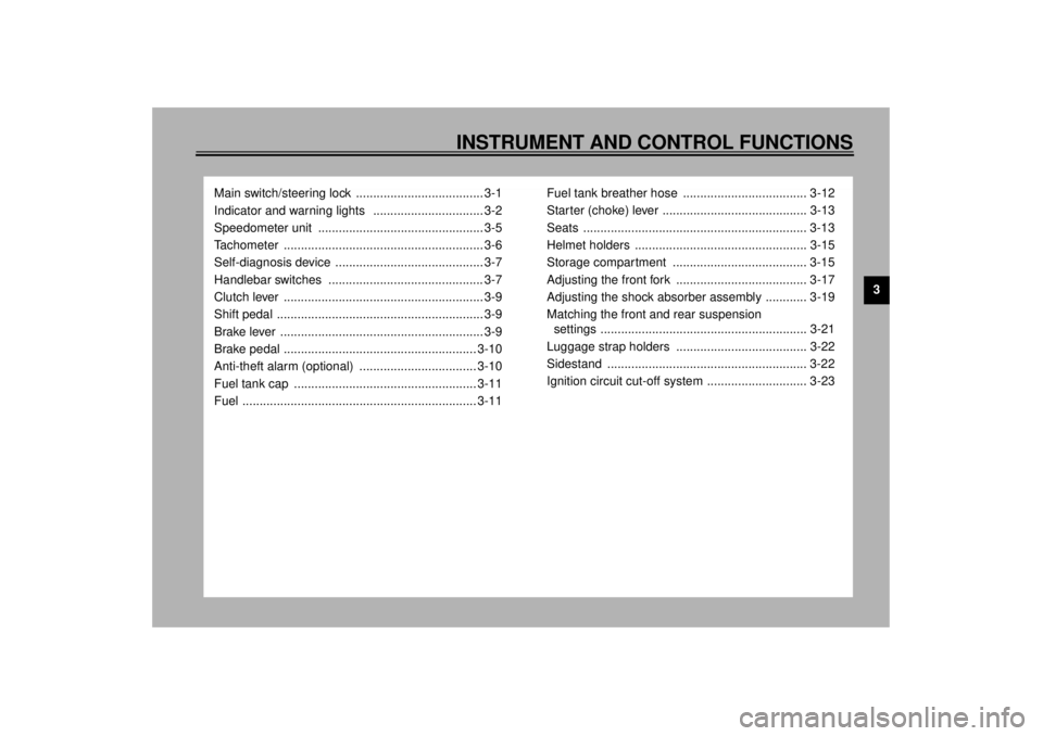
INSTRUMENT AND CONTROL FUNCTIONS
Main switch/steering lock ..................................... 3-1
Indicator and warning lights ................................ 3-2
Speedometer unit ................................................ 3-5
Tachometer .......................................................... 3-6
Self-diagnosis device ........................................... 3-7
Handlebar switches ............................................. 3-7
Clutch lever .......................................................... 3-9
Shift pedal ............................................................ 3-9
Brake lever ........................................................... 3-9
Brake pedal ........................................................ 3-10
Anti-theft alarm (optional) .................................. 3-10
Fuel tank cap ..................................................... 3-11
Fuel .................................................................... 3-11Fuel tank breather hose .................................... 3-12
Starter (choke) lever .......................................... 3-13
Seats ................................................................. 3-13
Helmet holders .................................................. 3-15
Storage compartment ....................................... 3-15
Adjusting the front fork ...................................... 3-17
Adjusting the shock absorber assembly ............ 3-19
Matching the front and rear suspension
settings ............................................................ 3-21
Luggage strap holders ...................................... 3-22
Sidestand .......................................................... 3-22
Ignition circuit cut-off system ............................. 3-23
E_5mt.book Page 1 Monday, September 18, 2000 9:08 AM
Page 25 of 118

INSTRUMENT AND CONTROL FUNCTIONS
3-10
3
The brake lever is equipped with a po-
sition adjusting dial. To adjust the dis-
tance between the brake lever and the
handlebar grip, turn the adjusting dial
while holding the lever pushed away
from the handlebar grip. Make sure that
the appropriate setting on the adjusting
dial is aligned with the arrow mark on
the brake lever.
EAU00162
Brake pedal The brake pedal is on the right side of
the motorcycle. To apply the rear
brake, press down on the brake pedal.
EAU00109
Anti-theft alarm (optional) This motorcycle can be equipped with
an optional anti-theft alarm by a
Yamaha dealer. Contact a Yamaha
dealer for more information.
1. Brake lever position adjusting dial
2. Arrow mark
a. Distance between brake lever and handlebar
grip
1. Brake pedal
E_5mt.book Page 10 Monday, September 18, 2000 9:08 AM
Page 114 of 118

10-INDEXAAir filter element, checking ..................... 6-17
Air intake duct ........................................ 6-20
Anti-theft alarm ...................................... 3-10BBattery ................................................... 6-37
Brake and clutch levers, checking and
lubricating ............................................ 6-34
Brake fluid, changing ............................. 6-30
Brake fluid level, checking...................... 6-29
Brake lever...............................................3-9
Brake light switch (rear), adjusting ......... 6-27
Brake pads, checking............................. 6-28
Brake pedal............................................ 3-10
Brake pedal, lubricating.......................... 6-34
Brake pedal position, adjusting .............. 6-27CCables, checking and lubricating............ 6-33
Carburetors, adjusting............................ 6-20
Care.........................................................7-1
Clutch lever ..............................................3-9
Clutch lever free play, adjusting ............. 6-25
Conversion table ......................................8-5
Coolant .................................................. 6-13
Changing .......................................... 6-15
Checking .......................................... 6-13
Cowlings and panels, removing and
installing ................................................6-6DDimmer switch .........................................3-7
Drive chain, lubricating ........................... 6-32
Drive chain slack ................................... 6-31
Adjusting .......................................... 6-31
Checking .......................................... 6-31EEngine break-in ....................................... 5-4
Engine oil and oil filter cartridge ............. 6-10
Engine stop switch................................... 3-8FFront and rear suspension settings ........ 3-21
Front fork, adjusting ............................... 3-17
Front fork, checking ............................... 6-35
Fuel ....................................................... 3-11
Fuel consumption, tips for reducing ......... 5-3
Fuel level warning light ............................ 3-2
Fuel tank breather hose ......................... 3-12
Fuel tank cap ......................................... 3-11
Fuses, replacing .................................... 6-38HHandlebar switches ................................. 3-7
Headlight bulb, replacing ....................... 6-39
Helmet holder ........................................ 3-15
High beam indicator light ......................... 3-2
Horn switch ............................................. 3-8IIdentification numbers ............................. 9-1
Idling speed, adjusting ........................... 6-21
Ignition circuit cut-off system.................. 3-23
Indicator and warning lights ..................... 3-2KKey identification number ........................ 9-1
LLight switch ..............................................3-8
Luggage strap holders ...........................3-22MMain switch/steering lock .........................3-1
Model label ..............................................9-2NNeutral indicator light ...............................3-2OOil level/coolant temperature warning
light ........................................................3-3PParking.....................................................5-4
Part locations ...........................................2-1
Pass switch ..............................................3-7
Periodic maintenance and lubrication
chart ......................................................6-3
Pre-operation check list ............................4-1SSafety information ....................................1-1
Seats .....................................................3-13
Passenger seat.................................3-14
Rider seat .........................................3-13
Self-diagnosis device ...............................3-7
Shifting .....................................................5-3
Shift pedal ................................................3-9
Shock absorber assembly, adjusting ......3-19
Sidestand ...............................................3-22
Sidestand, checking and lubricating .......6-34
Spark plugs, checking ..............................6-9
E_5mt.book Page 1 Monday, September 18, 2000 9:08 AM