lock YAMAHA YZF-R6 2013 User Guide
[x] Cancel search | Manufacturer: YAMAHA, Model Year: 2013, Model line: YZF-R6, Model: YAMAHA YZF-R6 2013Pages: 110, PDF Size: 2.43 MB
Page 77 of 110
PERIODIC MAINTENANCE AND ADJUSTMENT
6-26
6
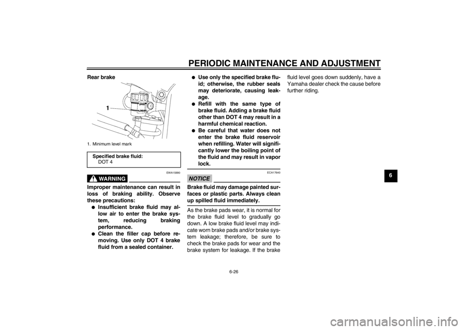
Rear brake
WARNING
EWA15990
Improper maintenance can result in
loss of braking ability. Observe
these precautions:●
Insufficient brake fluid may al-
low air to enter the brake sys-
tem, reducing braking
performance.
●
Clean the filler cap before re-
moving. Use only DOT 4 brake
fluid from a sealed container.
●
Use only the specified brake flu-
id; otherwise, the rubber seals
may deteriorate, causing leak-
age.
●
Refill with the same type of
brake fluid. Adding a brake fluid
other than DOT 4 may result in a
harmful chemical reaction.
●
Be careful that water does not
enter the brake fluid reservoir
when refilling. Water will signifi-
cantly lower the boiling point of
the fluid and may result in vapor
lock.
NOTICE
ECA17640
Brake fluid may damage painted sur-
faces or plastic parts. Always clean
up spilled fluid immediately.As the brake pads wear, it is normal for
the brake fluid level to gradually go
down. A low brake fluid level may indi-
cate worn brake pads and/or brake sys-
tem leakage; therefore, be sure to
check the brake pads for wear and the
brake system for leakage. If the brake fluid level goes down suddenly, have a
Yamaha dealer check the cause before
further riding.
1. Minimum level markSpecified brake fluid:
DOT 4
U1JSE1E0.book Page 26 Wednesday, June 6, 2012 10:05 AM
Page 78 of 110
PERIODIC MAINTENANCE AND ADJUSTMENT
6-27
6
EAU22731
Changing the brake fluid Have a Yamaha dealer change the
brake fluid at the intervals specified in
the TIP after the periodic maintenance
and lubrication chart. In addition, have
the oil seals of the master cylinders and
calipers as well as the brake hoses re-
placed at the intervals listed below or
whenever they are damaged or leak-
ing.●
Oil seals: Replace every two
years.
●
Brake hoses: Replace every four
years.
EAU22760
Drive chain slack The drive chain slack should be
checked before each ride and adjusted
if necessary.
EAU22774
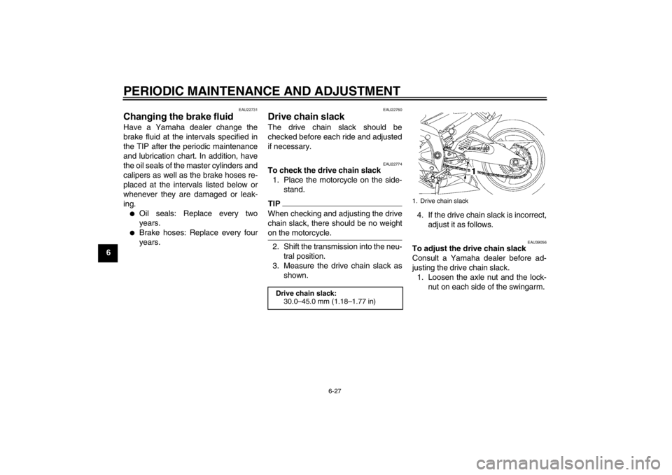
To check the drive chain slack1. Place the motorcycle on the side- stand.TIPWhen checking and adjusting the drive
chain slack, there should be no weight
on the motorcycle.2. Shift the transmission into the neu-tral position.
3. Measure the drive chain slack as shown. 4. If the drive chain slack is incorrect,
adjust it as follows.
EAU39056
To adjust the drive chain slack
Consult a Yamaha dealer before ad-
justing the drive chain slack.1. Loosen the axle nut and the lock- nut on each side of the swingarm.
Drive chain slack:30.0–45.0 mm (1.18–1.77 in)
1. Drive chain slack
U1JSE1E0.book Page 27 Wednesday, June 6, 2012 10:05 AM
Page 79 of 110
PERIODIC MAINTENANCE AND ADJUSTMENT
6-28
6
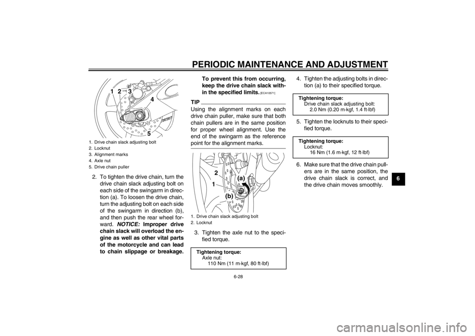
2. To tighten the drive chain, turn the
drive chain slack adjusting bolt on
each side of the swingarm in direc-
tion (a). To loosen the drive chain,
turn the adjusting bolt on each side
of the swingarm in direction (b),
and then push the rear wheel for-
ward. NOTICE: Improper drive
chain slack will overload the en-
gine as well as other vital parts
of the motorcycle and can lead
to chain slippage or breakage. To prevent this from occurring,
keep the drive chain slack with-
in the specified limits.
[ECA10571]
TIPUsing the alignment marks on each
drive chain puller, make sure that both
chain pullers are in the same position
for proper wheel alignment. Use the
end of the swingarm as the reference
point for the alignment marks.3. Tighten the axle nut to the speci-
fied torque. 4. Tighten the adjusting bolts in direc-
tion (a) to their specified torque.
5. Tighten the locknuts to their speci- fied torque.
6. Make sure that the drive chain pull- ers are in the same position, the
drive chain slack is correct, and
the drive chain moves smoothly.
1. Drive chain slack adjusting bolt
2. Locknut
3. Alignment marks
4. Axle nut
5. Drive chain puller
45
1
2
3
1. Drive chain slack adjusting bolt
2. Locknut
Tightening torque:Axle nut:110 Nm (11 m·kgf, 80 ft·lbf)
(a)
(b)
12
Tightening torque:
Drive chain slack adjusting bolt: 2.0 Nm (0.20 m·kgf, 1.4 ft·lbf)
Tightening torque: Locknut: 16 Nm (1.6 m·kgf, 12 ft·lbf)
U1JSE1E0.book Page 28 Wednesday, June 6, 2012 10:05 AM
Page 86 of 110

PERIODIC MAINTENANCE AND ADJUSTMENT
6-35
6
EAU23706
Replacing the fuses The main fuse, the fuel injection system
fuse, and fuse box 1 are located under
the rider seat. (See page 3-20.)TIPTo access the fuel injection system
fuse, remove the starter relay cover by
pulling it upward.
Fuse box 2 is located under panel A.
(See page 6-8.)
If a fuse is blown, replace it as follows.1. Turn the key to “OFF” and turn off the electrical circuit in question.
2. Remove the blown fuse, and then install a new fuse of the specified
amperage. WARNING! Do not
use a fuse of a higher amperage
rating than recommended to avoid causing extensive dam-
age to the electrical system and
possibly a fire.
[EWA15131]
3. Turn the key to “ON” and turn on
the electrical circuit in question to
check if the device operates.
4. If the fuse immediately blows again, have a Yamaha dealer
check the electrical system.
1. Main fuse
2. Fuel injection system spare fuse
3. Starter relay cover
4. Fuel injection system fuse
5. Fuse box 1
6. Backup fuse (for clock and immobilizer sys-tem)
7. Electronic throttle valve fuse
8. Spare fuse
2
1
5
6
3
748
1. Fuse box 2
2. Left radiator fan fuse
3. Right radiator fan fuse
4. Signaling system fuse
5. Ignition fuse
6. Taillight fuse
7. Headlight fuse
8. Spare fuse
Specified fuses: Main fuse:50.0 A
Fuel injection system fuse:
15.0 A
Electronic throttle valve fuse: 7.5 A
Backup fuse: 7.5 A
Radiator fan fuse:
15.0 A × 2
Ignition fuse: 15.0 A
Signaling system fuse: 10.0 A
Taillight fuse:
7.5 A
Headlight fuse: 15.0 A
U1JSE1E0.book Page 35 Wednesday, June 6, 2012 10:05 AM
Page 87 of 110
PERIODIC MAINTENANCE AND ADJUSTMENT
6-36
6
EAU39013
Replacing a headlight bulb This model is equipped with halogen
bulb headlights. If a headlight bulb
burns out, replace it as follows.NOTICE
ECA10650
Take care not to damage the follow-
ing parts:●
Headlight bulb
Do not touch the glass part of
the headlight bulb to keep it free
from oil, otherwise the transpar-
ency of the glass, the luminosity
of the bulb, and the bulb life will
be adversely affected. Thor-
oughly clean off any dirt and fin-
gerprints on the headlight bulb
using a cloth moistened with al-
cohol or thinner.
●
Headlight lens
Do not affix any type of tinted
film or stickers to the headlight
lens.
Do not use a headlight bulb of a
wattage higher than specified.
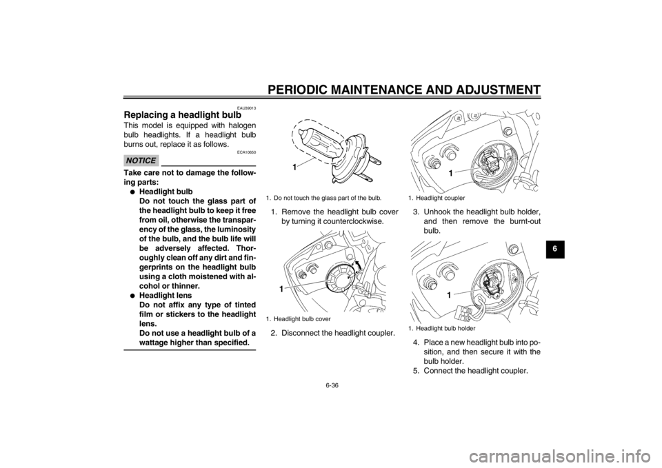
1. Remove the headlight bulb cover
by turning it counterclockwise.
2. Disconnect the headlight coupler. 3. Unhook the headlight bulb holder,
and then remove the burnt-out
bulb.
4. Place a new headlight bulb into po- sition, and then secure it with the
bulb holder.
5. Connect the headlight coupler.1. Do not touch the glass part of the bulb.
1. Headlight bulb cover
1
1. Headlight coupler
1. Headlight bulb holder
U1JSE1E0.book Page 36 Wednesday, June 6, 2012 10:05 AM
Page 88 of 110
PERIODIC MAINTENANCE AND ADJUSTMENT
6-37
66. Install the headlight bulb cover by
turning it clockwise.
7. Have a Yamaha dealer adjust the headlight beam if necessary.
EAU24181
Tail/brake light This model is equipped with an LED-
type tail/brake light.
If the tail/brake light does not come on,
have a Yamaha dealer check it.
EAU24204
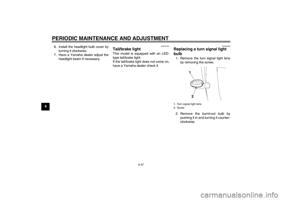
Replacing a turn signal light
bulb 1. Remove the turn signal light lensby removing the screw.
2. Remove the burnt-out bulb by pushing it in and turning it counter-
clockwise.1. Turn signal light lens
2. Screw
21
U1JSE1E0.book Page 37 Wednesday, June 6, 2012 10:05 AM
Page 89 of 110

PERIODIC MAINTENANCE AND ADJUSTMENT
6-38
6
3. Insert a new bulb into the socket,
push it in, and then turn it clock-
wise until it stops.
4. Install the lens by installing the screw. NOTICE: Do not over-
tighten the screw, otherwise the
lens may break.
[ECA11191] EAU24313
Replacing the license plate
light bulb 1. Remove the license plate light unit
by removing the screws.
2. Remove the license plate light bulb socket (together with the bulb) by
pulling it out. 3. Remove the burnt-out bulb by pull-
ing it out.
4. Insert a new bulb into the socket.
5. Install the socket (together with the bulb) by pushing it in.
6. Install the license plate light unit by installing the screws.
1. Turn signal light bulb
1. Screw
2. License plate light unit
1
2
1. License plate light bulb
2. License plate light bulb socket
1
2
U1JSE1E0.book Page 38 Wednesday, June 6, 2012 10:05 AM
Page 93 of 110
PERIODIC MAINTENANCE AND ADJUSTMENT
6-42
6
EAU25080
Rear wheel
EAU44953
To remove the rear wheel
WARNING
EWA10821
To avoid injury, securely support the
vehicle so there is no danger of it
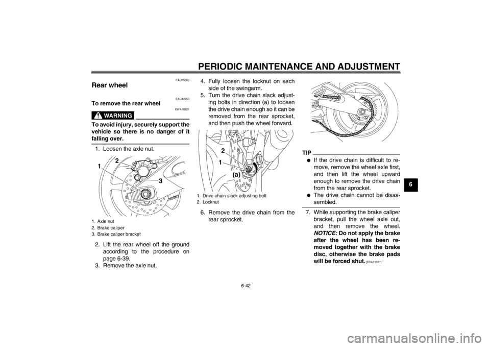
falling over.1. Loosen the axle nut.
2. Lift the rear wheel off the groundaccording to the procedure on
page 6-39.
3. Remove the axle nut. 4. Fully loosen the locknut on each
side of the swingarm.
5. Turn the drive chain slack adjust- ing bolts in direction (a) to loosen
the drive chain enough so it can be
removed from the rear sprocket,
and then push the wheel forward.
6. Remove the drive chain from the rear sprocket.
TIP●
If the drive chain is difficult to re-
move, remove the wheel axle first,
and then lift the wheel upward
enough to remove the drive chain
from the rear sprocket.
●
The drive chain cannot be disas-
sembled.
7. While supporting the brake caliperbracket, pull the wheel axle out,
and then remove the wheel.
NOTICE: Do not apply the brake
after the wheel has been re-
moved together with the brake
disc, otherwise the brake pads
will be forced shut.
[ECA11071]
1. Axle nut
2. Brake caliper
3. Brake caliper bracket
1
2
3
1. Drive chain slack adjusting bolt
2. Locknut
(a)
12
U1JSE1E0.book Page 42 Wednesday, June 6, 2012 10:05 AM
Page 94 of 110
PERIODIC MAINTENANCE AND ADJUSTMENT
6-43
6
EAU39173
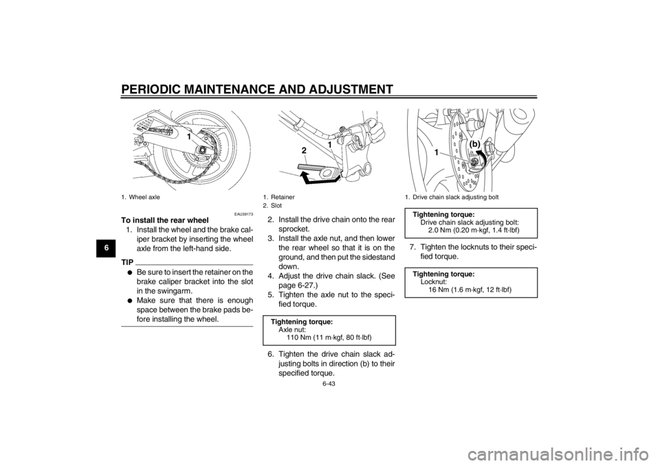
To install the rear wheel1. Install the wheel and the brake cal- iper bracket by inserting the wheel
axle from the left-hand side.TIP●
Be sure to insert the retainer on the
brake caliper bracket into the slot
in the swingarm.
●
Make sure that there is enough
space between the brake pads be-
fore installing the wheel.
2. Install the drive chain onto the rearsprocket.
3. Install the axle nut, and then lower the rear wheel so that it is on the
ground, and then put the sidestand
down.
4. Adjust the drive chain slack. (See page 6-27.)
5. Tighten the axle nut to the speci- fied torque.
6. Tighten the drive chain slack ad- justing bolts in direction (b) to their
specified torque. 7. Tighten the locknuts to their speci-
fied torque.
1. Wheel axle
1. Retainer
2. SlotTightening torque:Axle nut:110 Nm (11 m·kgf, 80 ft·lbf)
1. Drive chain slack adjusting boltTightening torque:Drive chain slack adjusting bolt:2.0 Nm (0.20 m·kgf, 1.4 ft·lbf)
Tightening torque: Locknut:
16 Nm (1.6 m·kgf, 12 ft·lbf)
(b)
1
U1JSE1E0.book Page 43 Wednesday, June 6, 2012 10:05 AM
Page 97 of 110
PERIODIC MAINTENANCE AND ADJUSTMENT
6-46
6
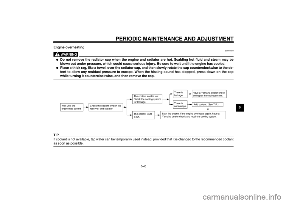
Engine overheating
WARNING
EWAT1040
●
Do not remove the radiator cap when the engine and radiator are hot. Scalding hot fluid and steam may be
blown out under pressure, which could cause serious injury. Be sure to wait until the engine has cooled.
●
Place a thick rag, like a towel, over the radiator cap, and then slowly rotate the cap counterclockwise to the de-
tent to allow any residual pressure to escape. When the hissing sound has stopped, press down on the cap
while turning it counterclockwise, and then remove the cap.
TIPIf coolant is not available, tap water can be temporarily used instead, provided that it is changed to the recommended coolant
as soon as possible.
Wait until the
engine has cooled.
Check the coolant level in the
reservoir and radiator.
The coolant level
is OK.The coolant level is low.
Check the cooling system
for leakage.
Have a Yamaha dealer checkand repair the cooling system.Add coolant. (See TIP.)
Start the engine. If the engine overheats again,
have a
Yamaha dealer check
and repair the cooling system.
There is
leakage.
There is
no leakage.
U1JSE1E0.book Page 46 Wednesday, June 6, 2012 10:05 AM