YAMAHA YZF-R6 2017 User Guide
Manufacturer: YAMAHA, Model Year: 2017, Model line: YZF-R6, Model: YAMAHA YZF-R6 2017Pages: 114, PDF Size: 4.2 MB
Page 11 of 114

Safety information
1-5
1
operator and may limit control
ability, therefore, such accesso-
ries are not recommended.
Use caution when adding electri-
cal accessories. If electrical ac-
cessories exceed the capacity of
the motorcycle’s electrical sys-
tem, an electric failure could re-
sult, which could cause a
dangerous loss of lights or engine
power.
Aftermarket Tires an d Rims
The tires and rims that came with your
motorcycle were designed to match
the performance capabilities and to
provide the best combination of han-
dling, braking, and comfort. Other
tires, rims, sizes, and combinations
may not be appropriate. See page 7-21
for tire specifications and for informa-
tion on servicing and replacing your
tires.
Transportin g the Motorcycle
Be sure to observe following instruc-
tions before transporting the motorcy-
cle in another vehicle. Remove all loose items from the
motorcycle.
Check that the fuel cock (if
equipped) is in the off position and
that there are no fuel leaks.
Shift the transmission into gear
(for models with a manual trans-
mission).
Secure the motorcycle with tie-
downs or suitable straps that are
attached to solid parts of the mo-
torcycle, such as the frame or up-
per front fork triple clamp (and not,
for example, to rubber-mounted handlebars or turn signals, or
parts that could break). Choose
the location for the straps carefully
so the straps will not rub against
painted surfaces during transport.
The suspension should be com-
pressed somewhat by the tie-
downs, if possible, so that the mo-
torcycle will not bounce exces-
sively during transport.
UBN6E0E0.book Page 5 Wednesday, January 25, 2017 1:28 PM
Page 12 of 114
Description
2-1
2
EAU63371
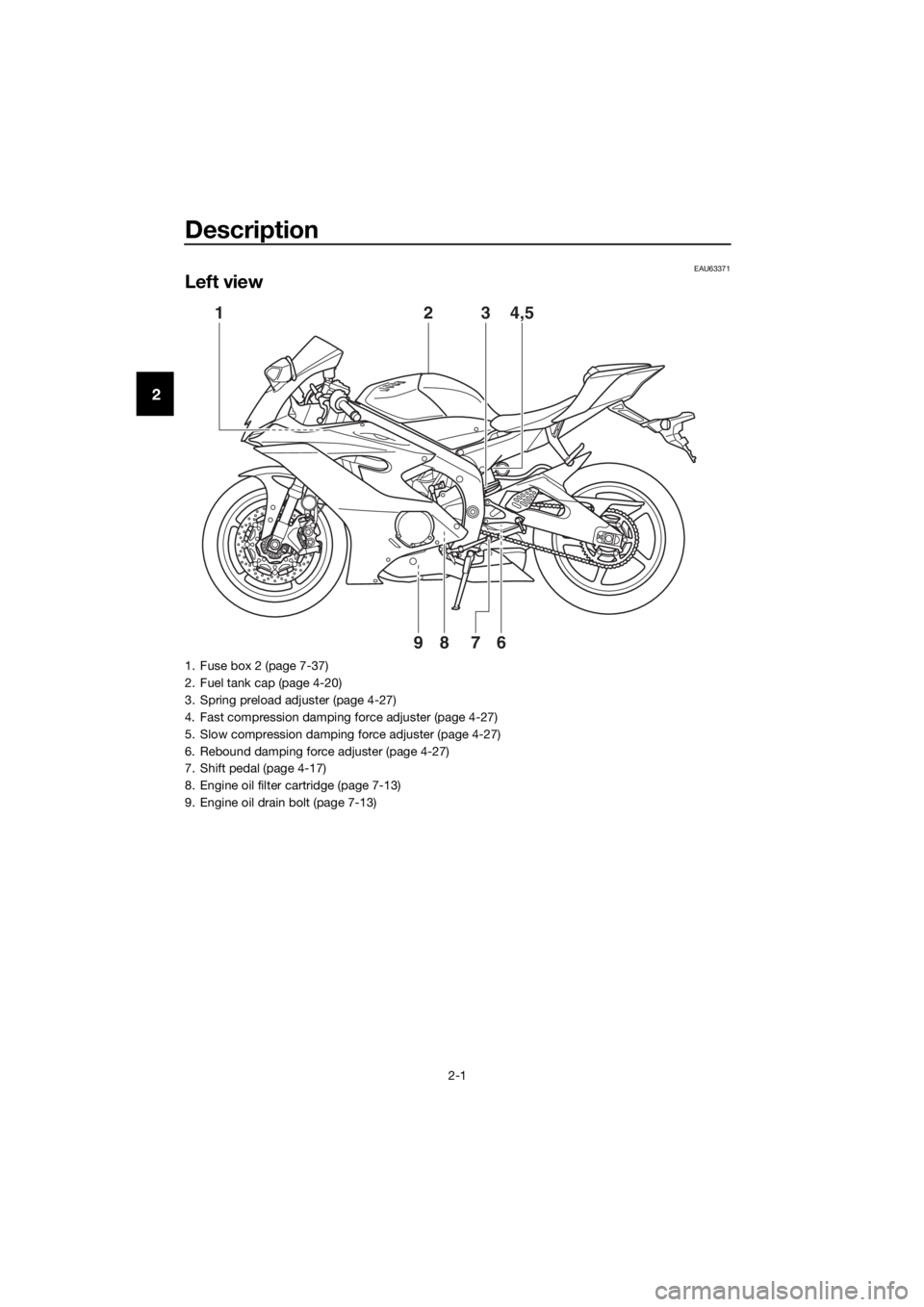
Left view
16789
3 4,52
1. Fuse box 2 (page 7-37)
2. Fuel tank cap (page 4-20)
3. Spring preload adjuster (page 4-27)
4. Fast compression damping force adjuster (page 4-27)
5. Slow compression damping force adjuster (page 4-27)
6. Rebound damping force adjuster (page 4-27)
7. Shift pedal (page 4-17)
8. Engine oil filter cartridge (page 7-13)
9. Engine oil drain bolt (page 7-13)
UBN6E0E0.book Page 1 Wednesday, January 25, 2017 1:28 PM
Page 13 of 114
Description
2-2
2
EAU63391
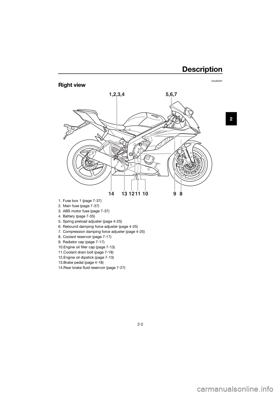
Right view
1,2,3,45,6,7
9
8
11121314 10
1. Fuse box 1 (page 7-37)
2. Main fuse (page 7-37)
3. ABS motor fuse (page 7-37)
4. Battery (page 7-35)
5. Spring preload adjuster (page 4-25)
6. Rebound damping force adjuster (page 4-25)
7. Compression damping force adjuster (page 4-25)
8. Coolant reservoir (page 7-17)
9. Radiator cap (page 7-17)
10.Engine oil filler cap (page 7-13)
11.Coolant drain bolt (page 7-18)
12.Engine oil dipstick (page 7-13)
13.Brake pedal (page 4-18)
14.Rear brake fluid reservoir (page 7-27)
UBN6E0E0.book Page 2 Wednesday, January 25, 2017 1:28 PM
Page 14 of 114

Description
2-3
2
EAU63401
Controls and instruments
12 4 35678
1. Clutch lever (page 4-17)
2. Left handlebar switches (page 4-4)
3. Main switch/steering lock (page 4-2)
4. Multi-function meter unit (page 4-8)
5. Front brake fluid reservoir (page 7-27)
6. Right handlebar switches (page 4-4)
7. Brake lever (page 4-18)
8. Throttle grip (page 7-20)
UBN6E0E0.book Page 3 Wednesday, January 25, 2017 1:28 PM
Page 15 of 114
Special features
3-1
3
EAU76422
D-mode ( drive mo de)
D-mode is an electronically controlled
engine performance system. This
model has three mode selections:
“STD”, “A”, and “B”.
WARNING
EWA18440
Do not chan ge the drive mo de while
the vehicle is movin g.
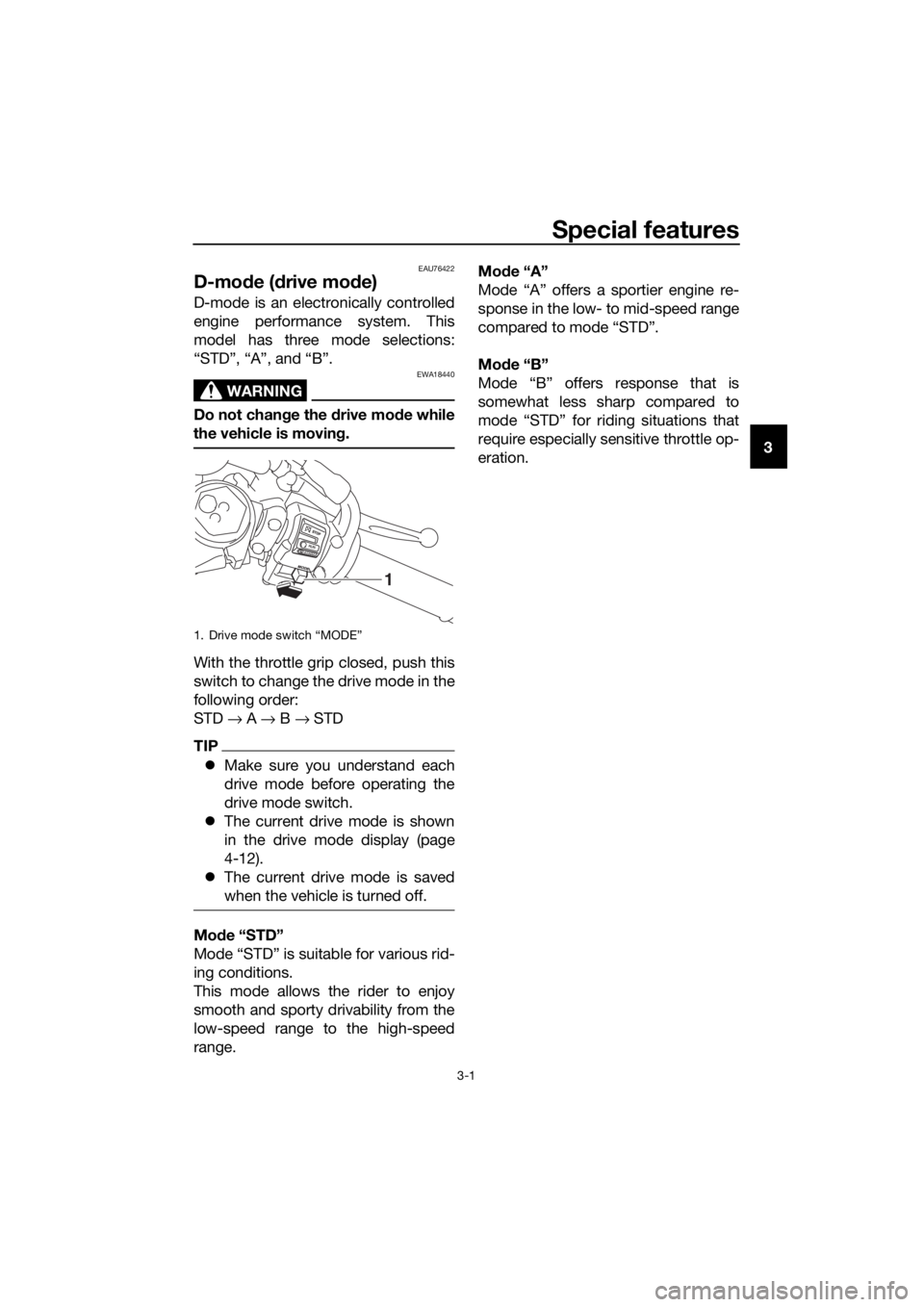
With the throttle grip closed, push this
switch to change the drive mode in the
following order:
STD → A → B → STD
TIP
Make sure you understand each
drive mode before operating the
drive mode switch.
The current drive mode is shown
in the drive mode display (page
4-12).
The current drive mode is saved
when the vehicle is turned off.
Mo de “STD”
Mode “STD” is suitable for various rid-
ing conditions.
This mode allows the rider to enjoy
smooth and sporty drivability from the
low-speed range to the high-speed
range. Mo
de “A”
Mode “A” offers a sportier engine re-
sponse in the low- to mid-speed range
compared to mode “STD”.
Mo de “B”
Mode “B” offers response that is
somewhat less sharp compared to
mode “STD” for riding situations that
require especially sensitive throttle op-
eration.
1. Drive mode switch “MODE”
1
UBN6E0E0.book Page 1 Wednesday, January 25, 2017 1:28 PM
Page 16 of 114
Special features
3-2
3
EAU79732
Traction control system
The traction control system (TCS)
helps maintain traction when acceler-
ating on slippery surfaces, such as un-
paved or wet roads. If sensors detect
that the rear wheel is starting to slip
(uncontrolled spinning), the traction
control system assists by regulating
engine power as needed until traction
is restored.
WARNING
EWA15433
The traction control system is not a
substitute for rid ing appropriately
for the con ditions. Traction control
cannot prevent loss of traction due
to excessive speed when entering
turns, when acceleratin g har d at a
sharp lean an gle, or while brakin g,
an d cannot prevent front wheel slip-
pin g. As with any vehicle, approach
surfaces that may be slippery with
caution an d avoi d especially slip-
pery surfaces.
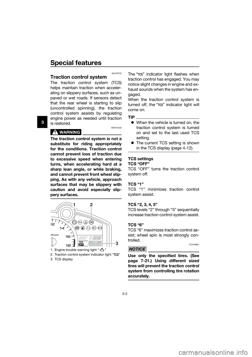
The “ ” indicator light flashes when
traction control has engaged. You may
notice slight changes in engine and ex-
haust sounds when the system has en-
gaged.
When the traction control system is
turned off, the “ ” indicator light will
come on.
TIP
When the vehicle is turned on, the
traction control system is turned
on and set to the last used TCS
setting.
The current TCS setting is shown
in the TCS display (page 4-12).
TCS settin gs
TCS “OFF”
TCS “OFF” turns the traction control
system off.
TCS “1”
TCS “1” minimizes traction control
system assist.
TCS “2, 3, 4, 5”
TCS levels “2” through “5” sequentially
increase traction control system assist.
TCS “6”
TCS “6” maximizes traction control as-
sist; wheel spin is most strongly con-
trolled.
NOTICE
ECA16801
Use only the specifie d tires. (See
pa ge 7-21.) Usin g different sized
tires will prevent the traction control
system from controllin g tire rotation
accurately.
1. Engine trouble warning light “ ”
2. Traction control system indicator light “ ”
3. TCS display
12
3
UBN6E0E0.book Page 2 Wednesday, January 25, 2017 1:28 PM
Page 17 of 114

Special features
3-3
3
Settin
g the traction control system
To turn TCS off
Stop the vehicle and: push up on the TCS switch for two
seconds to turn the traction con-
trol system off.
push down on the TCS switch to
turn the traction control system
back on.
TIP
Turn the traction control system off to
help free the rear wheel if it is stuck in
mud or sand, etc.
To change TCS settings
Stop the vehicle or close the throttle
and:
push up on the TCS switch to de-
crease traction control
(6→ 5→ 4→ 3→ 2→ 1).
push down on the TCS switch to
increase traction control
(1→ 2→ 3→ 4→ 5→ 6).
TIP
TCS settings can also be changed
when moving in straight line if the throt-
tle grip is held in a fixed position for two
seconds while in 4th, 5th, or 6th gear.
WARNING
EWA18940
Take extra precaution when chan g-
in g mo des while ri din g.
Resettin g the traction control sys-
tem
The traction control system will auto-
matically disable when: the front wheel or rear wheel
comes off the ground while riding.
excessive rear wheel spin is de-
tected while riding.
either wheel is rotated with the key
turned to “ON” (such as when per-
forming maintenance).
If the traction control system is dis-
abled, both the “ ” indicator light and
the “ ” warning light will come on.
Should this occur, try resetting the sys-
tem as follows. 1. Stop the vehicle and turn the key to “OFF”.
2. Wait a few seconds and then turn the key back to “ON”.
3. The “ ” indicator light should turn off and the system be en-
abled.
TIP
If the “ ” indicator light remains on af-
ter resetting, the vehicle may still be
ridden; however, have a Yamaha deal-
er check the vehicle as soon as possi-
ble.
4. Have a Yamaha dealer check thevehicle and turn off the “ ”
warning light.
1. Traction control system switch “TCS”
1
UBN6E0E0.book Page 3 Wednesday, January 25, 2017 1:28 PM
Page 18 of 114

Special features
3-4
3
EAU79480
Quick shift system
The quick shift system (QS) allows for
full-throttle, clutch lever-less, electron-
ically-assisted upshifts. When the shift
switch detects motion in the shift pedal
(page 4-17), engine power and drive
torque are momentarily adjusted to al-
low the upshift to occur.
TIP
The quick shift system operates
when traveling at least 20 km/h (12
mi/h) with an engine speed of
2000 r/min or higher, and only
when accelerating.
It does not operate when the
clutch lever is pulled.
UBN6E0E0.book Page 4 Wednesday, January 25, 2017 1:28 PM
Page 19 of 114

Instrument and control functions
4-1
4
EAU10978
Immo bilizer system
This vehicle is equipped with an immo-
bilizer system to help prevent theft by
re-registering codes in the standard
keys. This system consists of the fol-
lowing:
a code re-registering key (with a
red bow)
two standard keys (with a black
bow) that can be re-registered
with new codes
a transponder (which is installed in
the code re-registering key)
an immobilizer unit
an ECU
an immobilizer system indicator
light (See page 4-7.)
The key with the red bow is used to
register codes in each standard key.
Since re-registering is a difficult pro-
cess, take the vehicle along with all
three keys to a Yamaha dealer to have
them re-registered. Do not use the key
with the red bow for driving. It should
only be used for re-registering the
standard keys. Always use a standard
key for driving.
NOTICE
ECA11822
DO NOT LOSE THE CODE RE-
REGISTERING KEY! CONTACT
YOUR DEALER IMMEDIATELY
IF IT IS LOST! If the co de re-reg -
isterin g key is lost, reg istering
new co des in the stan dar d keys
is impossi ble. The stan dar d
keys can still be used to start
the vehicle, however if co de re-
re gisterin g is require d (i.e., if a
new stan dar d key is ma de or all
keys are lost) the entire immob i-
lizer system must be replaced .
Therefore, it is hi ghly recom-
mend ed to use either stan dar d
key an d keep the co de re-re gis-
tering key in a safe place.
Do not su bmerse any key in wa-
ter.
Do not expose any key to exces-
sively hig h temperatures.
Do not place any key close to
ma gnets (this includ es, but not
limite d to, pro ducts such as
speakers, etc.).
Do n
ot place items that transmit
electrical si gnals close to any
key.
Do not place heavy items on any
key.
Do not g rind any key or alter its
shape.
Do not d isassemble the plastic
part of any key.
Do not put two keys of any im-
mo bilizer system on the same
key rin g.
1. Code re-registering key (red bow)
2. Standard keys (black bow)
UBN6E0E0.book Page 1 Wednesday, January 25, 2017 1:28 PM
Page 20 of 114
Instrument and control functions
4-2
4
Keep the stan dar d keys as well
as keys of other immo bilizer
systems away from this vehi-
cle’s cod e re-registering key.
Keep other immo bilizer system
keys away from the main switch
as they may cause si gnal inter-
ference.
EAU10474
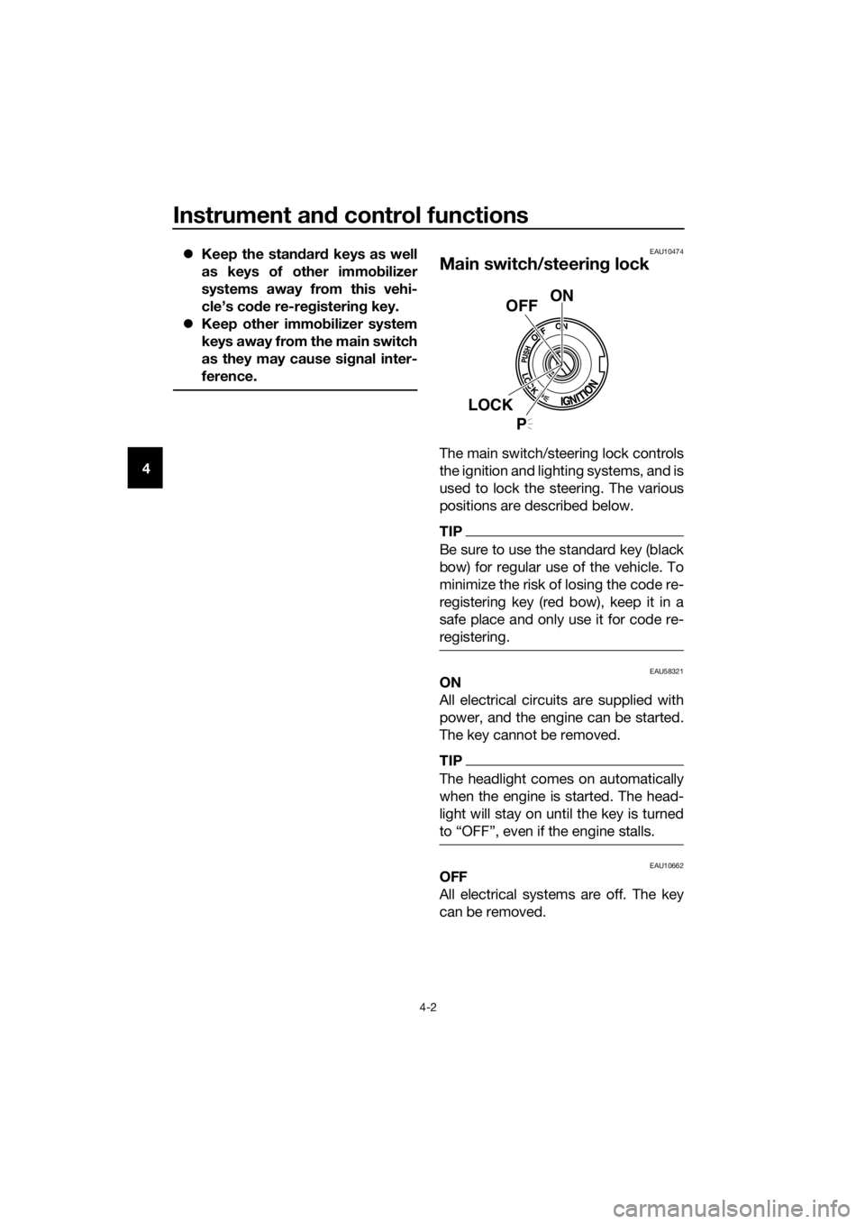
Main switch/steerin g lock
The main switch/steering lock controls
the ignition and lighting systems, and is
used to lock the steering. The various
positions are described below.
TIP
Be sure to use the standard key (black
bow) for regular use of the vehicle. To
minimize the risk of losing the code re-
registering key (red bow), keep it in a
safe place and only use it for code re-
registering.
EAU58321ON
All electrical circuits are supplied with
power, and the engine can be started.
The key cannot be removed.
TIP
The headlight comes on automatically
when the engine is started. The head-
light will stay on until the key is turned
to “OFF”, even if the engine stalls.
EAU10662OFF
All electrical systems are off. The key
can be removed.
ON
OFF
LOCK
P
UBN6E0E0.book Page 2 Wednesday, January 25, 2017 1:28 PM