warning YAMAHA YZF-R6 2020 User Guide
[x] Cancel search | Manufacturer: YAMAHA, Model Year: 2020, Model line: YZF-R6, Model: YAMAHA YZF-R6 2020Pages: 112, PDF Size: 5.44 MB
Page 26 of 112
Instrument and control functions
4-7
4
EAU69893
ABS warnin g li ght “ ”
This warning light comes on when the
vehicle is first turned on, and goes off
after starting riding. If the warning light
comes on while riding, the anti-lock
brake system may not work correctly.
WARNING
EWA16041
If the ABS warnin g li ght does not go
off after travelin g at a speed of 10
km/h (6 mi/h) or hi gher, or if the
warnin g li ght comes on or flashes
while ri din g, the b rake system re-
verts to conventional brakin g. If ei-
ther of the ab ove occurs, or if the
warnin g li ght does not come on at
all, use extra caution to avoi d possi-
b le wheel lock during emer gency
b rakin g. Have a Yamaha d ealer
check the brake system an d electri-
cal circuits as soon as possi ble.
EAU86020
Traction control system in dicator
li g ht “ ”
This indicator light will flash when trac-
tion control has engaged.
If the traction control system is turned
off, this indicator light will come on.
TIPWhen the vehicle is turned on, the light
should come on for a few seconds and
then go off. If the light does not come
on, or if the light remains on, have a
Yamaha dealer check the vehicle.
EAU80372
Shift li ght
This light can be set to come on and go
off at select engine speeds. (See page
4-15.)TIPWhen the vehicle is turned on, the light
will come on for a few seconds and
then go off. If the light does not come
on, have a Yamaha dealer check the
vehicle.
EAU80300
Immo bilizer system in dicator li ght
When the key is turned to “OFF” and
30 seconds have passed, the indicator
light will flash steadily to indicate the
immobilizer system is enabled. After 24
hours have passed, the indicator light
will stop flashing, however the immobi-
lizer system is still enabled. The electrical circuit of the indicator
light can be checked by turning the key
to “ON”. The indicator light should
come on for a few seconds, and then
go off.
If the indicator light does not come on
initially when the key is turned to “ON”,
if the indicator light remains on, or if the
indicator light flashes in a pattern (if a
problem is detected in the immobilizer
system, the immobilizer system indica-
tor light will flash in a pattern), have a
Yamaha dealer check the vehicle.
TIPIf the immobilizer system indicator light
flashes in the pattern, slowly 5 times
then quickly 2 times, this could be
caused by transponder interference. If
this occurs, try the following.1. Make sure there are no other im- mobilizer keys close to the main
switch. Other immobilizer system
keys may cause signal interfer-
ence and prevent the engine from
starting.
2. Use the code re-registering key to start the engine.
ABS
UBN6E2E0.book Page 7 Friday, December 7, 2018 2:56 PM
Page 27 of 112
Instrument and control functions
4-8
4
3. If the engine starts, turn it off, and
try starting the engine with the
standard keys.
4. If one or both of the standard keys do not start the engine, take the
vehicle and all 3 keys to a Yamaha
dealer to have the standard keys
re-registered.
EAU3904G
Multi-function meter unit
WARNING
EWA12423
Be sure to stop the vehicle before
making any setting changes to the
multi-function meter unit. Changing settings while riding can distract the
operator and increase the risk of an
accident.
The multi-function meter unit is
equipped with the following:
speedometer
tachometer
clock
lap timer
coolant temperature display
air temperature display
transmission gear display
drive mode display
TCS display
QS icon
multi-function display
display brightness and shift light
control modeTIPTo switch the multi-function meter
unit between kilometers and
miles, push the “SELECT” button
for one second.
The “ ” and “GPS” icons require
accessory parts to function.
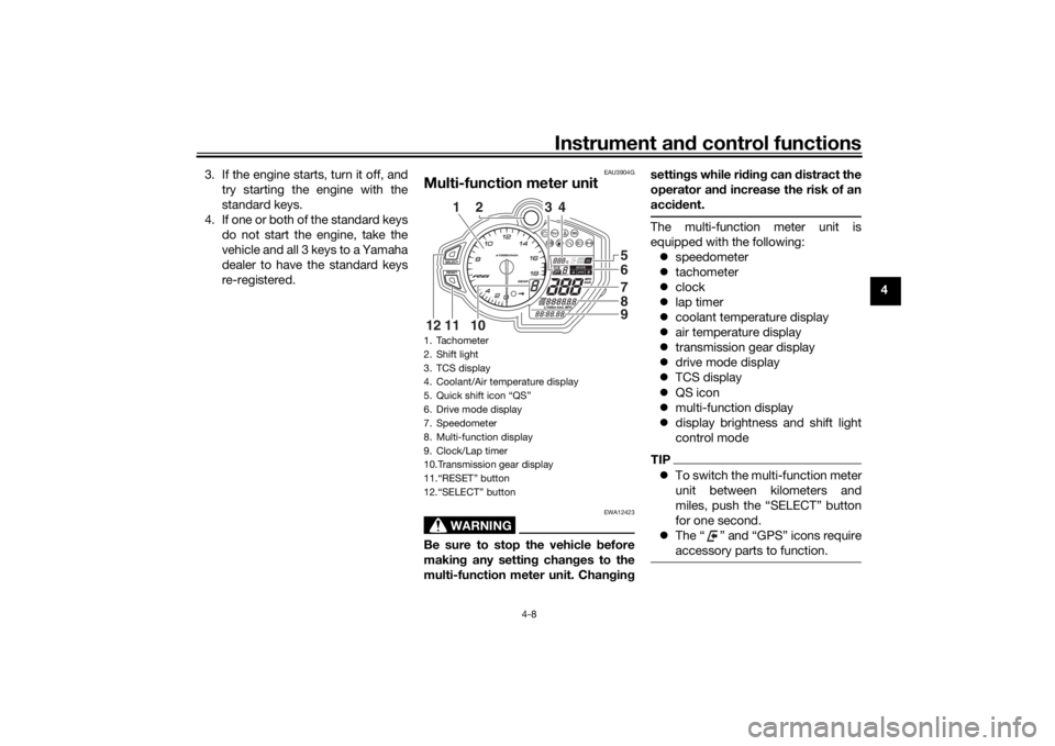
1. Tachometer
2. Shift light
3. TCS display
4. Coolant/Air temperature display
5. Quick shift icon “QS”
6. Drive mode display
7. Speedometer
8. Multi-function display
9. Clock/Lap timer
10.Transmission gear display
11.“RESET” button
12.“SELECT” button
65789
2
3
4
10
11
12
1
UBN6E3E0.book Page 8 Wednesday, September 25, 2019 3:31 PM
Page 30 of 112
Instrument and control functions
4-11
4Coolant temperature display
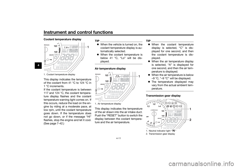
This display indicates the temperature
of the coolant from 41 °C to 124 °C in
1 °C increments.
If the coolant temperature is between
117 and 124 °C, the coolant tempera-
ture display flashes and the coolant
temperature warning light comes on. If
this occurs, reduce the load on the en-
gine by riding at a moderate pace, at
low rpm, until the coolant temperature
goes down. If the temperature does
not go down, or if the message “HI”
flashes, stop the engine and let it cool.
(See page 7-42.)
TIP
When the vehicle is turned on, the
coolant temperature display is au-
tomatically selected.
When the coolant temperature is
below 41 °C, “Lo” will be dis-
played.Air temperature display
This display indicates the temperature
of the air drawn into the air intake duct.
Push the “RESET” button to switch the
display between the coolant tempera-
ture and the air temperature.
TIPWhen the coolant temperature
display is selected, “C” is dis-
played for one second, and then
the coolant temperature is dis-
played.
When the air temperature display
is selected, “A” is displayed for
one second, and then the air tem-
perature is displayed.
When the air temperature is below
–9 °C, “–9 °C” will be displayed.
The temperature displayed may
vary from the actual ambient tem-
perature.Transmission gear display
1. Coolant temperature display
1
1. Air temperature display
1
1. Neutral indicator light “ ”
2. Transmission gear display
2 1
UBN6E3E0.book Page 11 Wednesday, September 25, 2019 3:32 PM
Page 32 of 112

Instrument and control functions
4-13
4 The multi-function display is equipped
with the following:
odometer
two tripmeters
fuel reserve tripmeter
instantaneous fuel consumption
average fuel consumption
total fuel used
Navi gatin g the multi-function dis-
play
Push the “SELECT” button to change
between the odometer “ODO”, tripme-
ters “TRIP 1” and “TRIP 2”, instanta-
neous fuel consumption “km/L”,
“L/100 km” or “MPG”, average fuel
consumption “AVE _ _ _._ km/L”, “AVE
_ _ _._ L/100 km” or “AVE _ _ _._ MPG”,
and total fuel used “_ _._” in the follow-
ing order:
ODO → TRIP 1 → TRIP 2 → km/L,
L/100 km or MPG → AVE _ _ _._ km/L,
AVE _ _ _._ L/100 km or AVE _ _ _._
MPG → _ _._ → ODO
O dometer an d tripmeters
The odometer shows the total distance
traveled by the vehicle. The tripmeters show the distance trav-
eled since they were last reset. To reset
a tripmeter, push the “RESET” button
for one second.
TIP
The odometer will lock at 999999.
The tripmeters will reset and con-
tinue counting after 9999.9 is
reached.Fuel reserve tripmeter
If the fuel level warning light comes on,
the display will automatically change to
the fuel reserve tripmeter “TRIP F” and
start counting the distance traveled
from that point. In this case, push the
“SELECT” button to switch the display
in the following order:
TRIP F → km/L, L/100 km or MPG →
AVE _ _ _._ km/L, AVE _ _ _._ L/100 km
or AVE _ _ _._ MPG → _ _._ → ODO →
TRIP 1 → TRIP 2 → TRIP F
TIPIf you do not reset the fuel reserve trip-
meter manually, after refueling and
traveling 5 km (3 mi), it will reset auto-
matically and disappear from the dis-
play.Instantaneous fuel consumption
This function calculates the fuel con-
sumption under current riding condi-
tions.
The instantaneous fuel consumption
display can be set to either “km/L” or
“L/100 km” when using kilometers, or
to “MPG” when using miles. When us-1. Instantaneous fuel consumption display
1
UBN6E2E0.book Page 13 Friday, December 7, 2018 2:56 PM
Page 37 of 112
Instrument and control functions
4-18
4
EAU63040
ABSThe Yamaha ABS (Anti-lock Brake
System) features a dual electronic con-
trol system, which acts on the front and
rear brakes independently.
Operate the brakes with ABS as you
would conventional brakes. If the ABS
is activated, a pulsating sensation may
be felt at the brake lever or brake ped-
al. In this situation, continue to apply
the brakes and let the ABS work; do
not “pump” the brakes as this will re-
duce braking effectiveness.
WARNING
EWA16051
Always keep a sufficient d istance
from the vehicle ahea d to match the
ri din g speed even with ABS.
The ABS performs best with
lon g b rakin g d istances.
On certain surfaces, such as
rou gh or g ravel roa ds, the b rak-
in g d istance may be lon ger with
the ABS than without.The ABS is monitored by an ECU,
which will revert the system to conven-
tional braking if a malfunction occurs.
TIP The ABS performs a self-diagno-
sis test each time the vehicle first
starts off after the key is turned to
“ON” and the vehicle has traveled
at a speed of 10 km/h (6 mi/h) or
higher. During this test, a “click-
ing” noise can be heard from the
hydraulic control unit, and if the
brake lever or brake pedal is even
slightly applied, a vibration can be
felt at the lever and pedal, but
these do not indicate a malfunc-
tion.
This ABS has a test mode which
allows the owner to experience
the pulsation at the brake lever or
brake pedal when the ABS is op-
erating. However, special tools are
required, so please consult your
Yamaha dealer.NOTICE
ECA20100
Be careful not to d amage the wheel
sensor or wheel sensor rotor; other-
wise, improper performance of the
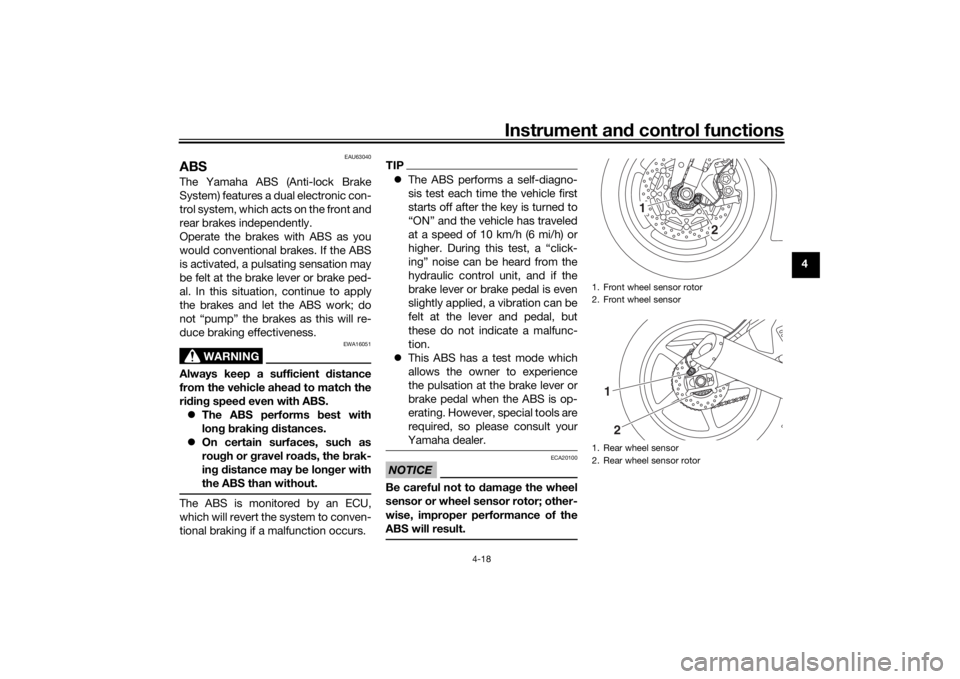
ABS will result.
1. Front wheel sensor rotor
2. Front wheel sensor
1. Rear wheel sensor
2. Rear wheel sensor rotor
1
2
12
UBN6E2E0.book Page 18 Friday, December 7, 2018 2:56 PM
Page 38 of 112

Instrument and control functions
4-19
4
EAU13076
Fuel tank capTo open the fuel tank cap
Open the fuel tank cap lock cover, in-
sert the key into the lock, and then turn
it 1/4 turn clockwise. The lock will be
released and the fuel tank cap can be
opened.
To close the fuel tank cap
With the key still inserted in the lock,
push down the fuel tank cap. Turn the
key 1/4 turn counterclockwise, remove
it, and then close the lock cover.
TIPThe fuel tank cap cannot be closed un-
less the key is in the lock. In addition,
the key cannot be removed if the cap is
not properly closed and locked.
WARNING
EWA11092
Make sure that the fuel tank cap is
properly close d after fillin g fuel.
Leakin g fuel is a fire hazar d.
EAU13222
FuelMake sure there is sufficient gasoline in
the tank.
WARNING
EWA10882
Gasoline an d g asoline vapors are
extremely flamma ble. To avoi d fires
an d explosions an d to re duce the
risk of injury when refuelin g, follow
these instructions.1. Before refueling, turn off the en- gine and be sure that no one is sit-
ting on the vehicle. Never refuel
while smoking, or while in the vi-
cinity of sparks, open flames, or
other sources of ignition such as
the pilot lights of water heaters
and clothes dryers.
2. Do not overfill the fuel tank. When refueling, be sure to insert the
pump nozzle into the fuel tank filler
hole. Stop filling when the fuel
reaches the bottom of the filler
tube. Because fuel expands when
it heats up, heat from the engine or
the sun can cause fuel to spill out
of the fuel tank.
1. Fuel tank cap lock cover
2. Unlock.
1
2
UBN6E2E0.book Page 19 Friday, December 7, 2018 2:56 PM
Page 39 of 112

Instrument and control functions
4-20
4
3. Wipe up any spilled fuel immedi- ately. NOTICE: Immediately
wipe off spilled fuel with a clean,
dry, soft cloth, since fuel may
deteriorate painted surfaces or
plastic parts.
[ECA10072]
4. Be sure to securely close the fuel tank cap.
WARNING
EWA15152
Gasoline is poisonous and can
cause injury or death. Handle gaso-
line with care. Never siphon gasoline
by mouth. If you should swallow
some gasoline or inhale a lot of gas-
oline vapor, or get some gasoline in
your eyes, see your doctor immedi- ately. If gasoline spills on your skin,
wash with soap and water. If gaso-
line spills on your clothing, change
your clothes.
EAU86072
Your Yamaha engine was designed to
use unleaded gasoline with a research
octane number of 95 or higher. If en-
gine knocking or pinging occurs, use a
gasoline of a different brand or higher
octane rating.
TIP
This mark identifies the recom-
mended fuel for this vehicle as
specified by European regulation
(EN228).
Confirm the gasoline pump nozzle
has the same fuel identification
mark.Gasohol
There are two types of gasohol: gaso-
hol containing ethanol and that con-
taining methanol. Gasohol containing
ethanol can be used if the ethanol con-
tent does not exceed 10% (E10). Gas-
ohol containing methanol is not
recommended by Yamaha because it
can cause damage to the fuel system
or vehicle performance problems.
1. Fuel tank filler tube
2. Maximum fuel level
1
2
Recommended fuel:
Unleaded gasoline (E10 acceptable)
Octane number (RON): 95
Fuel tank capacity: 17 L (4.5 US gal, 3.7 Imp.gal)
Fuel tank reserve:
3.4 L (0.90 US gal, 0.75 Imp.gal)
E5
E10
UBN6E3E0.book Page 20 Monday, September 2, 2019 6:55 PM
Page 41 of 112

Instrument and control functions
4-22
4
EAU13435
Catalytic converterThe exhaust system contains catalytic
converter(s) to reduce harmful exhaust
emissions.
WARNING
EWA10863
The exhaust system is hot after op-
eration. To prevent a fire hazar d or
b urns:
Do not park the vehicle near
possi ble fire hazar ds such as
g rass or other materials that
easily burn.
Park the vehicle in a place
where pe destrians or chil dren
are not likely to touch the hot
exhaust system.
Make sure that the exhaust sys-
tem has coole d down before
d oin g any maintenance work.
Do not allow the en gine to i dle
more than a few minutes. Lon g
i d lin g can cause a buil d-up of
heat.
EAU79900
SeatsPassen ger seat
To remove the passenger seat1. Insert the key into the seat lock, and then turn it clockwise.
2. Lift the front of the passenger seat and pull it forward.
To install the passenger seat1. Insert the projection on the rear of the passenger seat into the seat
holder as shown, and then push
the front of the seat down to lock
it in place. 2. Remove the key.
Ri der seat
To remove the rider seat
1. Remove the passenger seat.
2. Pull up the corners on the rear of the rider seat as shown, remove
the bolts with the hexagon wrench
located under the passenger seat,
and then pull the seat off.
1. Seat lock
2. Unlock.
1
2
1. Projection
2. Seat holder
2
1
UBN6E2E0.book Page 22 Friday, December 7, 2018 2:56 PM
Page 42 of 112

Instrument and control functions
4-23
4
To install the rider seat
1. Insert the projection into the seatholder as shown, then place the
seat in the original position. 2. Install the bolts with the hexagon
wrench.
3. Insert the hexagon wrench back into its holder.
4. Install the passenger seat.
TIPMake sure that the seats are properly
secured before riding.
EAU39672
Rear view mirrorsThe rear view mirrors of this vehicle
can be folded forward or backward for
parking in narrow spaces. Fold the mir-
rors back to their original position be-
fore riding.
WARNING
EWA14372
Be sure to fol d the rear view mirrors
b ack to their ori ginal position before
ri din g.
1. Bolt
1. Hexagon wrench
11
1. Seat holder
2. Projection
2
1
1. Riding position
2. Parking position1
22
1
UBN6E2E0.book Page 23 Friday, December 7, 2018 2:56 PM
Page 43 of 112
Instrument and control functions
4-24
4
EAU79923
A djustin g the front forkThis model is equipped with adjustable
suspension. The spring preload, re-
bound damping force, and compres-
sion damping force of each leg can be
adjusted.
WARNING
EWA10181
Always a djust both fork le gs equally,
otherwise poor han dlin g an d loss of
sta bility may result.NOTICE
ECA24120
Use extra care to avoi d scratch-
in g the ano dize d finish of the
a d justin g nuts an d b olts when
makin g suspension ad just-
ments.
To avoi d d amag ing the suspen-
sion’s internal mechanisms, do
not attempt to turn beyon d the
maximum or minimum settin gs.Sprin g preloa d
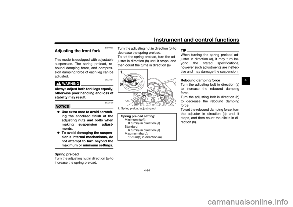
Turn the adjusting nut in direction (a) to
increase the spring preload. Turn the adjusting nut in direction (b) to
decrease the spring preload.
To set the spring preload, turn the ad-
juster in direction (b) until it stops, and
then count the turns in direction (a).
TIPWhen turning the spring preload ad-
juster in direction (a), it may turn be-
yond the stated specifications,
however such adjustments are ineffec-
tive and may damage the suspension.Re
boun d d ampin g force
Turn the adjusting bolt in direction (a)
to increase the rebound damping
force.
Turn the adjusting bolt in direction (b)
to decrease the rebound damping
force.
To set the rebound damping force, turn
the adjuster in direction (a) until it
stops, and then count the clicks in di-
rection (b).
1. Spring preload adjusting nut
Sprin g preloa d settin g:
Minimum (soft): 0 turn(s) in direction (a)
Standard: 6 turn(s) in direction (a)
Maximum (hard):
15 turn(s) in direction (a)(a)
(b)
1
UBN6E2E0.book Page 24 Friday, December 7, 2018 2:56 PM