warning light YAMAHA YZF-R6 2020 User Guide
[x] Cancel search | Manufacturer: YAMAHA, Model Year: 2020, Model line: YZF-R6, Model: YAMAHA YZF-R6 2020Pages: 112, PDF Size: 5.44 MB
Page 37 of 112
Instrument and control functions
4-18
4
EAU63040
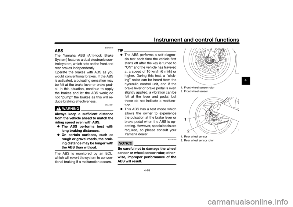
ABSThe Yamaha ABS (Anti-lock Brake
System) features a dual electronic con-
trol system, which acts on the front and
rear brakes independently.
Operate the brakes with ABS as you
would conventional brakes. If the ABS
is activated, a pulsating sensation may
be felt at the brake lever or brake ped-
al. In this situation, continue to apply
the brakes and let the ABS work; do
not “pump” the brakes as this will re-
duce braking effectiveness.
WARNING
EWA16051
Always keep a sufficient d istance
from the vehicle ahea d to match the
ri din g speed even with ABS.
The ABS performs best with
lon g b rakin g d istances.
On certain surfaces, such as
rou gh or g ravel roa ds, the b rak-
in g d istance may be lon ger with
the ABS than without.The ABS is monitored by an ECU,
which will revert the system to conven-
tional braking if a malfunction occurs.
TIP The ABS performs a self-diagno-
sis test each time the vehicle first
starts off after the key is turned to
“ON” and the vehicle has traveled
at a speed of 10 km/h (6 mi/h) or
higher. During this test, a “click-
ing” noise can be heard from the
hydraulic control unit, and if the
brake lever or brake pedal is even
slightly applied, a vibration can be
felt at the lever and pedal, but
these do not indicate a malfunc-
tion.
This ABS has a test mode which
allows the owner to experience
the pulsation at the brake lever or
brake pedal when the ABS is op-
erating. However, special tools are
required, so please consult your
Yamaha dealer.NOTICE
ECA20100
Be careful not to d amage the wheel
sensor or wheel sensor rotor; other-
wise, improper performance of the
ABS will result.
1. Front wheel sensor rotor
2. Front wheel sensor
1. Rear wheel sensor
2. Rear wheel sensor rotor
1
2
12
UBN6E2E0.book Page 18 Friday, December 7, 2018 2:56 PM
Page 38 of 112

Instrument and control functions
4-19
4
EAU13076
Fuel tank capTo open the fuel tank cap
Open the fuel tank cap lock cover, in-
sert the key into the lock, and then turn
it 1/4 turn clockwise. The lock will be
released and the fuel tank cap can be
opened.
To close the fuel tank cap
With the key still inserted in the lock,
push down the fuel tank cap. Turn the
key 1/4 turn counterclockwise, remove
it, and then close the lock cover.
TIPThe fuel tank cap cannot be closed un-
less the key is in the lock. In addition,
the key cannot be removed if the cap is
not properly closed and locked.
WARNING
EWA11092
Make sure that the fuel tank cap is
properly close d after fillin g fuel.
Leakin g fuel is a fire hazar d.
EAU13222
FuelMake sure there is sufficient gasoline in
the tank.
WARNING
EWA10882
Gasoline an d g asoline vapors are
extremely flamma ble. To avoi d fires
an d explosions an d to re duce the
risk of injury when refuelin g, follow
these instructions.1. Before refueling, turn off the en- gine and be sure that no one is sit-
ting on the vehicle. Never refuel
while smoking, or while in the vi-
cinity of sparks, open flames, or
other sources of ignition such as
the pilot lights of water heaters
and clothes dryers.
2. Do not overfill the fuel tank. When refueling, be sure to insert the
pump nozzle into the fuel tank filler
hole. Stop filling when the fuel
reaches the bottom of the filler
tube. Because fuel expands when
it heats up, heat from the engine or
the sun can cause fuel to spill out
of the fuel tank.
1. Fuel tank cap lock cover
2. Unlock.
1
2
UBN6E2E0.book Page 19 Friday, December 7, 2018 2:56 PM
Page 54 of 112
Operation and important rid ing points
6-1
6
EAU15952
Read the Owner’s Manual carefully to
become familiar with all controls. If
there is a control or function you do not
understand, ask your Yamaha dealer.
WARNING
EWA10272
Failure to familiarize yourself with
the controls can lead to loss of con-
trol, which coul d cause an acci dent
or injury.
EAU73452
TIPThis model is equipped with: a lean angle sensor. This sensor
stops the engine in case of a turn-
over. In this case, turn the main
switch off and then on. Failing to
do so will prevent the engine from
starting even though the engine
will crank when pushing the start
switch.
an engine auto-stop system. The
engine stops automatically if left
idling for 20 minutes. If the engine
stops, simply push the start
switch to restart the engine.
EAU79944
Startin g the en gineThe ignition circuit cut-off system will
enable starting when:
the transmission is in the neutral
position or
the transmission is in gear, the
sidestand is up, and the clutch le-
ver is pulled.
To start the engine1. Turn the main switch on and set the engine stop switch to the run
position.
2. Confirm the indicator and warning light(s) come on for a few sec-
onds, and then go off. (See page
4-5.)TIPDo not start the engine if the en-
gine trouble warning light or the oil
level warning light remains on.
The ABS warning light should
come on and stay on until the ve-
hicle reaches a traveling speed of
10 km/h (6 mi/h).
UBN6E2E0.book Page 1 Friday, December 7, 2018 2:56 PM
Page 56 of 112
Operation and important rid ing points
6-3
6 3. Open the throttle gradually, and at
the same time, release the clutch
lever slowly.
4. After starting out, close the throt- tle, and at the same time, quickly
pull the clutch lever in.
5. Shift the transmission into second gear. (Make sure not to shift the
transmission into the neutral posi-
tion.)
6. Open the throttle part way and gradually release the clutch lever.
7. Follow the same procedure when shifting to the next higher gear.
EAU85380
To decelerate
1. Release the throttle and apply both the front and the rear brakes
smoothly to slow the motorcycle.
2. As the vehicle decelerates, shift to a lower gear.
3. When the engine is about to stall or runs roughly, pull the clutch le-
ver in, use the brakes to slow the
motorcycle, and continue to
downshift as necessary. 4. Once the motorcycle has
stopped, the transmission can be
shifted into the neutral position.
The neutral indicator light should
come on and then the clutch lever
can be released.
WARNING
EWA17380
Improper brakin g can cause
loss of control or traction. Al-
ways use b oth brakes an d apply
them smoothly.
Make sure that the motorcycle
and the en gine have sufficiently
slowe d b efore shiftin g to a low-
er gear. En gag in g a lower gear
when the vehicle or en gine
speed is too hi gh coul d make
the rear wheel lose traction or
the en gine to over-rev. This
coul d cause loss of control, an
acci dent an d injury. It coul d also
cause en gine or drive train dam-
a g e.
EAU16811
Tips for re ducin g fuel con-
sumptionFuel consumption depends largely on
your riding style. Consider the follow-
ing tips to reduce fuel consumption:
Shift up swiftly, and avoid high en-
gine speeds during acceleration.
Do not rev the engine while shift-
ing down, and avoid high engine
speeds with no load on the en-
gine.
Turn the engine off instead of let-
ting it idle for an extended length
of time (e.g., in traffic jams, at traf-
fic lights or at railroad crossings).
UBN6E2E0.book Page 3 Friday, December 7, 2018 2:56 PM
Page 75 of 112
Periodic maintenance an d a djustment
7-18
7
TIPBe sure to wipe off spilled oil on any
parts after the engine and exhaust sys-
tem have cooled down.NOTICE
ECA11621
In or der to prevent clutch slip-
pa ge (since the en gine oil also
lu bricates the clutch), do not
mix any chemical additives. Do
not use oils with a diesel speci-
fication of “CD” or oils of a hi gh-
er quality than specifie d. In
a ddition, do not use oils lab eled
“ENERGY CONSERVING II” or
hi gher.
Make sure that no forei gn mate-
rial enters the crankcase.
15. Check the filler cap O-ring for damage, and replace it if neces-
sary.
16. Install and tighten the oil filler cap.
17. Start the engine, and then let it idle for several minutes while checking
it for oil leakage. If oil is leaking,
immediately turn the engine off
and check for the cause.TIPAfter the engine is started, the engine
oil level warning light should go off if
the oil level is sufficient.NOTICE
ECA10402
If the oil level warnin g li ght flickers
or remains on even if the oil level is
correct, imme diately turn the en gine
off an d have a Yamaha dealer check
the vehicle.18. Turn the engine off, and then check the oil level and correct it if
necessary.
19. Check the dipstick O-ring for damage, and replace it if neces-
sary.
20. Install the cowlings.
EAU85450
Why Yamalu beYAMALUBE oil is a Genuine YAMAHA
Part born of the engineers’ passion
and belief that engine oil is an impor-
tant liquid engine component. We form
teams of specialists in the fields of me-
chanical engineering, chemistry, elec-
tronics and track testing, and have
them develop the engine together with
the oil it will use. Yamalube oils take full
advantage of the base oil’s qualities
and blend in the ideal balance of addi-
tives to make sure the final oil clears
our performance standards. Thus,
Yamalube mineral, semisynthetic and
synthetic oils have their own distinct
characters and value. Yamaha’s expe-
rience gained over many years of re-
search and development into oil since
the 1960’s helps make Yamalube the
best choice for your Yamaha engine.
Recommen ded en gine oil:
See page 9-1.
Oil quantity: Oil change:
2.40 L (2.54 US qt, 2.11 Imp.qt)
With oil filter removal: 2.60 L (2.75 US qt, 2.29 Imp.qt)
UBN6E2E0.book Page 18 Friday, December 7, 2018 2:56 PM
Page 94 of 112
Periodic maintenance an d a djustment
7-37
7
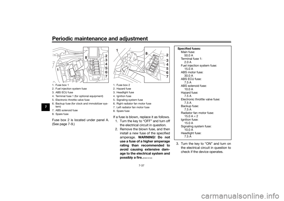
Fuse box 2 is located under panel A.
(See page 7-9.) If a fuse is blown, replace it as follows.
1. Turn the key to “OFF” and turn off the electrical circuit in question.
2. Remove the blown fuse, and then install a new fuse of the specified
amperage. WARNING! Do not
use a fuse of a hi gher ampera ge
ratin g than recommen ded to
avoi d causin g extensive d am-
a g e to the electrical system an d
possi bly a fire.
[EWA15132]
3. Turn the key to “ON” and turn on
the electrical circuit in question to
check if the device operates.
1. Fuse box 1
2. Fuel injection system fuse
3. ABS ECU fuse
4. Terminal fuse 1 (for optional equipment)
5. Electronic throttle valve fuse
6. Backup fuse (for clock and immobilizer sys-tem)
7. ABS solenoid fuse
8. Spare fuse
2
1
345
8
67
1. Fuse box 2
2. Hazard fuse
3. Headlight fuse
4. Ignition fuse
5. Signaling system fuse
6. Right radiator fan motor fuse
7. Left radiator fan motor fuse
8. Spare fuse
2
1
345
8
67
Specifie d fuses:
Main fuse:
50.0 A
Te r m i n a l f u s e 1 :
2.0 A
Fuel injection system fuse: 15.0 A
ABS motor fuse: 30.0 A
ABS ECU fuse:
7.5 A
ABS solenoid fuse: 10.0 A
Hazard fuse: 7.5 A
Electronic throttle valve fuse:
7.5 A
Backup fuse: 7.5 A
Radiator fan motor fuse: 15.0 A × 2
Ignition fuse:
15.0 A
Signaling system fuse: 10.0 A
Headlight fuse: 7.5 A
UBN6E2E0.book Page 37 Friday, December 7, 2018 2:56 PM
Page 96 of 112
Periodic maintenance an d a djustment
7-39
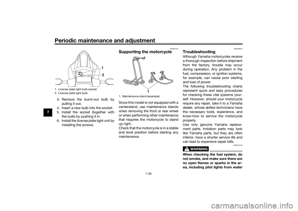
7 3. Remove the burnt-out bulb by
pulling it out.
4. Insert a new bulb into the socket.
5. Install the socket (together with the bulb) by pushing it in.
6. Install the license plate light unit by installing the screws.
EAU67131
Supportin g the motorcycleSince this model is not equipped with a
centerstand, use maintenance stands
when removing the front or rear wheel
or when performing other maintenance
that requires the motorcycle to stand
up right.
Check that the motorcycle is in a stable
and level position before starting any
maintenance.
EAU25872
Trou bleshootin gAlthough Yamaha motorcycles receive
a thorough inspection before shipment
from the factory, trouble may occur
during operation. Any problem in the
fuel, compression, or ignition systems,
for example, can cause poor starting
and loss of power.
The following troubleshooting charts
represent quick and easy procedures
for checking these vital systems your-
self. However, should your motorcycle
require any repair, take it to a Yamaha
dealer, whose skilled technicians have
the necessary tools, experience, and
know-how to service the motorcycle
properly.
Use only genuine Yamaha replace-
ment parts. Imitation parts may look
like Yamaha parts, but they are often
inferior, have a shorter service life and
can lead to expensive repair bills.
WARNING
EWA15142
When checkin g the fuel system, do
not smoke, an d make sure there are
no open flames or sparks in the ar-
ea, inclu din g pilot li ghts from water
1. License plate light bulb socket
2. License plate light bulb
1
2
1. Maintenance stand (example)
1
UBN6E2E0.book Page 39 Friday, December 7, 2018 2:56 PM
Page 101 of 112

Motorcycle care and stora ge
8-2
8
chemicals such as, solvents,
g
asoline, rust removers, b rake
flui d, or antifreeze, etc.
Before washin g
1. Park the vehicle out of direct sun- light and allow it to cool. This will
help avoid water spots.
2. Make sure all caps, covers, elec- trical couplers and connectors are
tightly installed.
3. Cover the muffler end with a plas- tic bag and a strong rubber band.
4. Pre-soak stubborn stains like in- sects or bird droppings with a wet
towel for a few minutes.
5. Remove road grime and oil stains with a quality degreasing agent
and a plastic-bristle brush or
sponge. NOTICE: Do not use
d eg reasin g a gent on areas re-
quirin g lu brication such as
seals, gaskets, an d wheel axles.
Follow pro duct instructions.
[ECA26290]
Washin g
1. Rinse off any degreaser and spray down the vehicle with a garden
hose. Use only enough pressure
to do the job. Avoid spraying wa-
ter directly into the muffler, instru-
ment panel, air inlet, or other inner
areas such as underseat storage
compartments.
2. Wash the vehicle with a quality au- tomotive-type detergent mixed
with cool water and a soft, clean
towel or sponge. Use an old tooth-
brush or plastic-bristle brush for
hard-to-reach places. NOTICE:
Use col d water if the vehicle has
b een exposed to salt. Warm wa-
ter will increase salt’s corrosive
properties.
[ECA26301]
3. For windshield-equipped vehicles: Clean the windshield with a soft
towel or sponge dampened with
water and a pH neutral detergent.
If necessary, use a high-quality
windshield cleaner or polish for
motorcycles. NOTICE: Never use
any stron g chemicals to clean
the wind shield. Additionally,
some cleanin g compoun ds for plastic may scratch the win
d-
shiel d, so b e sure to test all
cleanin g pro ducts before gen-
eral application.
[ECA26310]
4. Rinse off thoroughly with clean water. Be sure to remove all deter-
gent residues, as they can be
harmful to plastic parts.
After washin g
1. Dry the vehicle with a chamois or absorbent towel, preferably mi-
crofiber terrycloth.
2. For drive chain-equipped models: Dry and then lubricate the drive
chain to prevent rust.
3. Use a chrome polish to shine chrome, aluminum, and stainless
steel parts. Often the thermally in-
duced discoloring of stainless
steel exhaust systems can be re-
moved through polishing.
4. Apply a corrosion protection spray on all metal parts including
chrome or nickel-plated surfaces.
WARNING! Do not apply sili- cone or oil spray to seats, han d
g rips, ru bber foot pe gs or tire
trea ds. Otherwise these parts
UBN6E2E0.book Page 2 Friday, December 7, 2018 2:56 PM
Page 102 of 112
![YAMAHA YZF-R6 2020 User Guide Motorcycle care and stora ge
8-3
8 will
become slippery, which
coul d cause loss of control.
Thorou ghly clean the surfaces
of these parts before operatin g
the vehicle.
[EWA20650]
5. Treat rubber, YAMAHA YZF-R6 2020 User Guide Motorcycle care and stora ge
8-3
8 will
become slippery, which
coul d cause loss of control.
Thorou ghly clean the surfaces
of these parts before operatin g
the vehicle.
[EWA20650]
5. Treat rubber,](/img/51/54310/w960_54310-101.png)
Motorcycle care and stora ge
8-3
8 will
become slippery, which
coul d cause loss of control.
Thorou ghly clean the surfaces
of these parts before operatin g
the vehicle.
[EWA20650]
5. Treat rubber, vinyl, and unpainted plastic parts with a suitable care
product.
6. Touch up minor paint damage caused by stones, etc.
7. Wax all painted surfaces using a non-abrasive wax or use a detail
spray for motorcycles.
8. When finished cleaning, start the engine and let it idle for several
minutes to help dry any remaining
moisture.
9. If the headlight lens has fogged up, start the engine and turn on
the headlight to help remove the
moisture.
10. Let the vehicle dry completely be- fore storing or covering it.NOTICE
ECA26320
Do not apply wax to ru bber or
unpainte d plastic parts.
Do not use a brasive polishin g
compoun ds as they will wear
away the paint.
Apply sprays an d wax sparin gly.
Wipe off excess afterwar ds.
WARNING
EWA20660
Contaminants left on the b rakes or
tires can cause loss of control. Make sure there is no lu bricant
or wax on the brakes or tires.
If necessary, wash the tires with
warm water an d a mil d d eter-
g ent.
If necessary, clean the brake
d iscs an d pa ds with brake
cleaner or acetone.
Before ri din g at hi gher spee ds,
test the vehicle’s b raking per-
formance an d cornerin g b ehav-
ior.
EAU83472
Stora geAlways store the vehicle in a cool, dry
place. If necessary, protect it against
dust with a porous cover. Be sure the
engine and the exhaust system are
cool before covering the vehicle. If the
vehicle often sits for weeks at a time
between uses, the use of a quality fuel
stabilizer is recommended after each
fill-up.NOTICE
ECA21170
Storin g the vehicle in a poorly
ventilate d room or coverin g it
with a tarp, while it is still wet,
will allow water an d humi dity to
seep in an d cause rust.
To prevent corrosion, avoi d
d amp cellars, sta bles (b ecause
of the presence of ammonia)
an d areas where stron g chemi-
cals are store d.Lon g term stora ge
Before storing the vehicle long term (60
days or more):
UBN6E2E0.book Page 3 Friday, December 7, 2018 2:56 PM
Page 109 of 112

11-1
11
Index
AABS....................................................... 4-18
ABS warning light ................................... 4-7
Air filter element.................................... 7-20
Auxiliary DC connector ......................... 4-29BBattery .................................................. 7-35
Brake and clutch levers, checking and
lubricating........................................... 7-32
Brake and shift pedals, checking and lubricating........................................... 7-32
Brake fluid, changing............................ 7-28
Brake fluid level, checking.................... 7-27
Brake lever............................................ 4-17
Brake lever free play, checking ............ 7-25
Brake light switches ............................. 7-26
Brake pedal .......................................... 4-17CCables, checking and lubricating ......... 7-31
Canister ................................................ 7-14
Care ........................................................ 8-1
Catalytic converter ............................... 4-22
Clutch lever........................................... 4-16
Clutch lever free play, adjusting ........... 7-24
Coolant ................................................. 7-19
Coolant temperature warning light ......... 4-6
Cowlings and panels, removing and installing ............................................... 7-9DData recording, vehicle......................... 10-2
Diagnostic connector ........................... 10-2
Dimmer switch........................................ 4-4
D-mode (drive mode).............................. 3-1
Drive chain, cleaning and lubricating ... 7-30 Drive chain slack .................................. 7-29
Drive mode switch ................................. 4-5
EEngine break-in ...................................... 6-4
Engine idling speed, checking ............. 7-20
Engine oil and oil filter cartridge........... 7-15
Engine overheating .............................. 7-42
Engine serial number ........................... 10-1
Engine trouble warning light .................. 4-6
EXUP system ....................................... 4-28FFront and rear brake pads, checking ... 7-26
Front fork, adjusting ............................. 4-24
Front fork, checking ............................. 7-34
Fuel ...................................................... 4-19
Fuel consumption, tips for reducing ...... 6-3
Fuel level warning light........................... 4-6
Fuel tank cap........................................ 4-19
Fuel tank overflow hose ....................... 4-21
Fuses, replacing ................................... 7-36HHandlebar switches ............................... 4-3
Hazard switch ........................................ 4-4
High beam indicator light ....................... 4-5
Horn switch ............................................ 4-4IIdentification numbers ......................... 10-1
Ignition circuit cut-off system .............. 4-30
Immobilizer system ................................ 4-1
Immobilizer system indicator light ......... 4-7
Indicator lights and warning lights ......... 4-5LLicense plate light bulb, replacing ....... 7-38
MMain switch/steering lock ....................... 4-2
Maintenance and lubrication, periodic ... 7-5
Maintenance, emission control
system .................................................. 7-3
Matte color, caution................................ 8-1
Model label ........................................... 10-1
Multi-function meter unit ........................ 4-8NNeutral indicator light ............................. 4-5OOil level warning light .............................. 4-5PParking.................................................... 6-4
Part locations.......................................... 2-1
Pass switch............................................. 4-4QQuick shift system .................................. 3-4RRear view mirrors .................................. 4-23SSafety information................................... 1-1
Seats ..................................................... 4-22
Shifting.................................................... 6-2
Shift light ................................................. 4-7
Shift pedal............................................. 4-17
Shock absorber assembly, adjusting ... 4-26
Sidestand.............................................. 4-29
Sidestand, checking and lubricating .... 7-33
Spark plugs, checking .......................... 7-13
Special features ...................................... 3-1
Specifications ......................................... 9-1
Starting the engine ................................. 6-1
Steering, checking ................................ 7-34
UBN6E2E0.book Page 1 Friday, December 7, 2018 2:56 PM