Diag YAMAHA YZF-R6 2020 Owners Manual
[x] Cancel search | Manufacturer: YAMAHA, Model Year: 2020, Model line: YZF-R6, Model: YAMAHA YZF-R6 2020Pages: 112, PDF Size: 5.44 MB
Page 7 of 112

Table of contents
Checking and lubricating the
sidestand ...................................7-33
Lubricating the swingarm pivots ...7-33
Checking the front fork..................7-34
Checking the steering ...................7-34
Checking the wheel bearings ........7-35
Battery ...........................................7-35
Replacing the fuses .......................7-36
Vehicle lights .................................7-38
Replacing the license plate light bulb ............................................7-38
Supporting the motorcycle............7-39
Troubleshooting ............................7-39
Troubleshooting chart ...................7-41
Motorcycle care an d stora ge ..........8-1
Matte color caution .........................8-1
Care .................................................8-1
Storage ............................................8-3
Specifications ....................................9-1
Consumer information ...................10-1
Identification numbers ...................10-1
Diagnostic connector ....................10-2
Vehicle data recording ..................10-2
In dex ................................................11-1
UBN6E2E0.book Page 2 Friday, December 7, 2018 2:56 PM
Page 25 of 112

Instrument and control functions
4-6
4
on, or if the light remains on after con-
firming that the oil level is correct (see
page 7-15), have a Yamaha dealer
check the vehicle.
EAU11369
Fuel level warnin
g li ght “ ”
This warning light comes on when you
are low on fuel. When the fuel level
drops below approximately 3.4 L (0.90
US gal, 0.75 Imp.gal), the light will
come on to remind you to refuel as
soon as possible.
When the vehicle is turned on, the light
will perform a circuit check (come on
for a few seconds and then go off).
If the warning light does not come on
during the circuit check, or if the warn-
ing light remains on after refueling,
have a Yamaha dealer check the vehi-
cle.TIPIf a malfunction is detected, the fuel
level warning light will flash repeatedly.
Have a Yamaha dealer check the vehi-
cle.
EAU72931
Coolant temperature warnin g
li g ht “ ”
This warning light comes on if the en-
gine overheats. If this occurs, reduce
the load on the engine immediately. If
message “HI” flashes in the coolant
temperature display, stop the vehicle,
then stop the engine and let the engine
cool.
The electrical circuit of the warning
light can be checked by turning the ve-
hicle on. The warning light should
come on for a few seconds, and then
go off.
If the warning light does not come on
initially when the vehicle is turned on,
or if the warning light remains on, have
a Yamaha dealer check the electrical
circuit.NOTICE
ECA10022
Do not continue to operate the en-
g ine if it is overheatin g.
TIP For radiator-fan-equipped vehi-
cles, the radiator fan(s) automati-
cally switch on or off according to
the coolant temperature in the ra-
diator.
If the engine overheats, see page
7-42 for further instructions.
EAU73172
Engine trou ble warnin g li ght “ ”
This warning light comes on if a prob-
lem is detected in the engine or other
vehicle control system. If this occurs,
have a Yamaha dealer check the on-
board diagnostic system.TIPWhen the vehicle is turned on, the light
will come on for a few seconds and
then go off. If the light does not come
on, or if the light remains on, have a
Yamaha dealer check the vehicle.
UBN6E2E0.book Page 6 Friday, December 7, 2018 2:56 PM
Page 37 of 112

Instrument and control functions
4-18
4
EAU63040
ABSThe Yamaha ABS (Anti-lock Brake
System) features a dual electronic con-
trol system, which acts on the front and
rear brakes independently.
Operate the brakes with ABS as you
would conventional brakes. If the ABS
is activated, a pulsating sensation may
be felt at the brake lever or brake ped-
al. In this situation, continue to apply
the brakes and let the ABS work; do
not “pump” the brakes as this will re-
duce braking effectiveness.
WARNING
EWA16051
Always keep a sufficient d istance
from the vehicle ahea d to match the
ri din g speed even with ABS.
The ABS performs best with
lon g b rakin g d istances.
On certain surfaces, such as
rou gh or g ravel roa ds, the b rak-
in g d istance may be lon ger with
the ABS than without.The ABS is monitored by an ECU,
which will revert the system to conven-
tional braking if a malfunction occurs.
TIP The ABS performs a self-diagno-
sis test each time the vehicle first
starts off after the key is turned to
“ON” and the vehicle has traveled
at a speed of 10 km/h (6 mi/h) or
higher. During this test, a “click-
ing” noise can be heard from the
hydraulic control unit, and if the
brake lever or brake pedal is even
slightly applied, a vibration can be
felt at the lever and pedal, but
these do not indicate a malfunc-
tion.
This ABS has a test mode which
allows the owner to experience
the pulsation at the brake lever or
brake pedal when the ABS is op-
erating. However, special tools are
required, so please consult your
Yamaha dealer.NOTICE
ECA20100
Be careful not to d amage the wheel
sensor or wheel sensor rotor; other-
wise, improper performance of the
ABS will result.
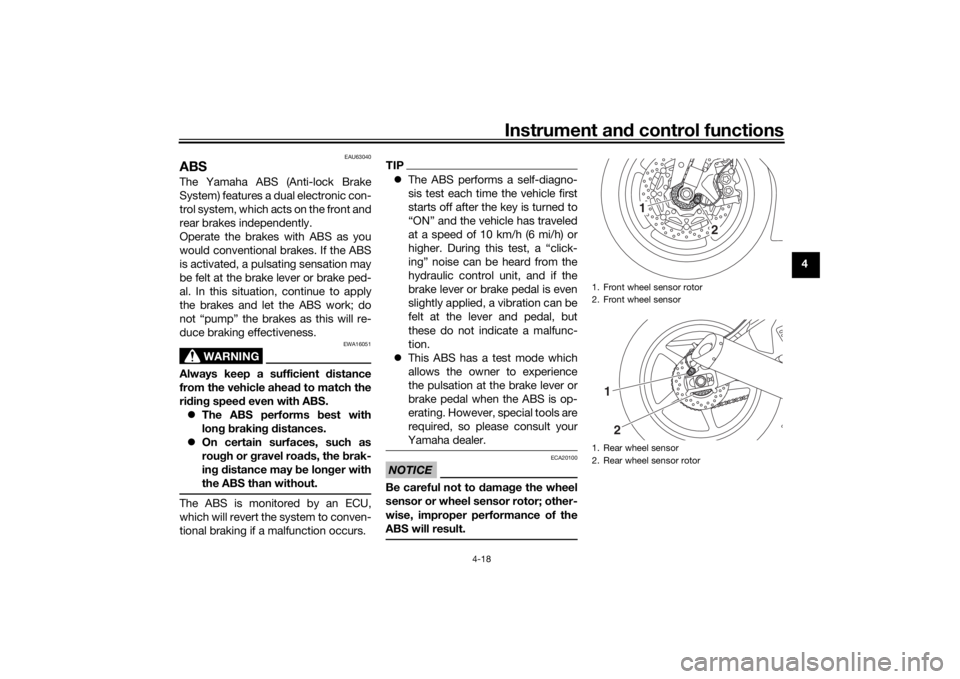
1. Front wheel sensor rotor
2. Front wheel sensor
1. Rear wheel sensor
2. Rear wheel sensor rotor
1
2
12
UBN6E2E0.book Page 18 Friday, December 7, 2018 2:56 PM
Page 62 of 112

Periodic maintenance an d a djustment
7-5
7
EAU71352
General maintenance an d lu brication chartNO. ITEM CHECK OR MAINTENANCE JOB ODOMETER READING
ANNUAL
CHECK
1000 km
(600 mi) 10000 km
(6000 mi) 20000 km
(12000 mi) 30000 km
(18000 mi) 40000 km
(24000 mi)
1 *Dia
gnostic system
check • Perform dynamic inspection us-
ing Yamaha diagnostic tool.
• Check the error codes. √√√√√√
2 *Air filter element • Replace. Every 40000 km (24000 mi)
3Clutch • Check operation.
•Adjust. √√√√√
4 *Front brake • Check operation, fluid level, and
for fluid leakage.
• Replace brake pads if necessary. √√√√√√
5 *Rear brake • Check operation, fluid level, and
for fluid leakage.
• Replace brake pads if necessary. √√√√√√
6 *Brake hoses • Check for cracks or damage.
√√√√√
• Replace. Every 4 years
7 *Brake flui d • Change. Every 2 years
8 *Wheels • Check runout and for damage.
• Replace if necessary. √√√√
9 *Tires • Check tread depth and for dam-
age.
• Replace if necessary.
• Check air pressure.
• Correct if necessary. √√√√√
10 *Wheel bearin gs • Check bearing for looseness or
damage. √√√√
UBN6E2E0.book Page 5 Friday, December 7, 2018 2:56 PM
Page 70 of 112

Periodic maintenance an d a djustment
7-13
7 To install the cowling
1. Place cowling D in its original po-
sition, and then install the bolts.
2. Install cowling C and panel B.
EAU79970
Panels A an d B
To remove a panelRemove the quick fasteners, and then
pull the panel off as shown.
To install a panelPlace the panel in the original position,
and then install the quick fasteners.
EAU19653
Checkin g the spark plu gsThe spark plugs are important engine
components, which should be
checked periodically, preferably by a
Yamaha dealer. Since heat and depos- its will cause any spark plug to slowly
erode, they should be removed and
checked in accordance with the peri-
odic maintenance and lubrication
chart. In addition, the condition of the
spark plugs can reveal the condition of
the engine.
The porcelain insulator around the
center electrode of each spark plug
should be a medium-to-light tan (the
ideal color when the vehicle is ridden
normally), and all spark plugs installed
in the engine should have the same
color. If any spark plug shows a dis-
tinctly different color, the engine could
be operating improperly. Do not at-
tempt to diagnose such problems
yourself. Instead, have a Yamaha deal-
er check the vehicle.
If a spark plug shows signs of elec-
trode erosion and excessive carbon or
other deposits, it should be replaced.
1. Panel A
2. Quick fastener
2
1
UBN6E2E0.book Page 13 Friday, December 7, 2018 2:56 PM
Page 107 of 112

Consumer information
10-2
10
The model label is affixed to the frame
under the passenger seat. (See page
4-22.) Record the information on this
label in the space provided. This infor-
mation will be needed when ordering
spare parts from a Yamaha dealer.
EAU69910
Dia
gnostic connectorThe diagnostic connector is located as
shown.
EAU85300
Vehicle data recor din gThis model’s ECU stores certain vehi-
cle data to assist in the diagnosis of
malfunctions and for research, statisti-
cal analysis and development purpos-
es.
Although the sensors and recorded
data will vary by model, the main data
points are:
Vehicle status and engine perfor-
mance data
Fuel-injection and emission-relat-
ed data
This data will be uploaded only when a
special Yamaha diagnostic tool is at-
tached to the vehicle, such as when
maintenance checks or service proce-
dures are performed.
Vehicle data uploaded will be handled
appropriately according to the follow-
ing Privacy Policy.
Privacy Policy
1. Diagnostic connector
1
https://www.yamaha-motor.eu/eu/
privacy/privacy-policy.aspx
UBN6E2E0.book Page 2 Friday, December 7, 2018 2:56 PM
Page 109 of 112

11-1
11
Index
AABS....................................................... 4-18
ABS warning light ................................... 4-7
Air filter element.................................... 7-20
Auxiliary DC connector ......................... 4-29BBattery .................................................. 7-35
Brake and clutch levers, checking and
lubricating........................................... 7-32
Brake and shift pedals, checking and lubricating........................................... 7-32
Brake fluid, changing............................ 7-28
Brake fluid level, checking.................... 7-27
Brake lever............................................ 4-17
Brake lever free play, checking ............ 7-25
Brake light switches ............................. 7-26
Brake pedal .......................................... 4-17CCables, checking and lubricating ......... 7-31
Canister ................................................ 7-14
Care ........................................................ 8-1
Catalytic converter ............................... 4-22
Clutch lever........................................... 4-16
Clutch lever free play, adjusting ........... 7-24
Coolant ................................................. 7-19
Coolant temperature warning light ......... 4-6
Cowlings and panels, removing and installing ............................................... 7-9DData recording, vehicle......................... 10-2
Diagnostic connector ........................... 10-2
Dimmer switch........................................ 4-4
D-mode (drive mode).............................. 3-1
Drive chain, cleaning and lubricating ... 7-30 Drive chain slack .................................. 7-29
Drive mode switch ................................. 4-5
EEngine break-in ...................................... 6-4
Engine idling speed, checking ............. 7-20
Engine oil and oil filter cartridge........... 7-15
Engine overheating .............................. 7-42
Engine serial number ........................... 10-1
Engine trouble warning light .................. 4-6
EXUP system ....................................... 4-28FFront and rear brake pads, checking ... 7-26
Front fork, adjusting ............................. 4-24
Front fork, checking ............................. 7-34
Fuel ...................................................... 4-19
Fuel consumption, tips for reducing ...... 6-3
Fuel level warning light........................... 4-6
Fuel tank cap........................................ 4-19
Fuel tank overflow hose ....................... 4-21
Fuses, replacing ................................... 7-36HHandlebar switches ............................... 4-3
Hazard switch ........................................ 4-4
High beam indicator light ....................... 4-5
Horn switch ............................................ 4-4IIdentification numbers ......................... 10-1
Ignition circuit cut-off system .............. 4-30
Immobilizer system ................................ 4-1
Immobilizer system indicator light ......... 4-7
Indicator lights and warning lights ......... 4-5LLicense plate light bulb, replacing ....... 7-38
MMain switch/steering lock ....................... 4-2
Maintenance and lubrication, periodic ... 7-5
Maintenance, emission control
system .................................................. 7-3
Matte color, caution................................ 8-1
Model label ........................................... 10-1
Multi-function meter unit ........................ 4-8NNeutral indicator light ............................. 4-5OOil level warning light .............................. 4-5PParking.................................................... 6-4
Part locations.......................................... 2-1
Pass switch............................................. 4-4QQuick shift system .................................. 3-4RRear view mirrors .................................. 4-23SSafety information................................... 1-1
Seats ..................................................... 4-22
Shifting.................................................... 6-2
Shift light ................................................. 4-7
Shift pedal............................................. 4-17
Shock absorber assembly, adjusting ... 4-26
Sidestand.............................................. 4-29
Sidestand, checking and lubricating .... 7-33
Spark plugs, checking .......................... 7-13
Special features ...................................... 3-1
Specifications ......................................... 9-1
Starting the engine ................................. 6-1
Steering, checking ................................ 7-34
UBN6E2E0.book Page 1 Friday, December 7, 2018 2:56 PM