reset YAMAHA YZF-R6 2020 Owners Manual
[x] Cancel search | Manufacturer: YAMAHA, Model Year: 2020, Model line: YZF-R6, Model: YAMAHA YZF-R6 2020Pages: 112, PDF Size: 5.44 MB
Page 18 of 112

Special features
3-3
3Setting
the traction control system
To turn TCS off
Stop the vehicle and: push up on the TCS switch for two
seconds to turn the traction con-
trol system off.
push down on the TCS switch to
turn the traction control system
back on.TIPTurn the traction control system off to
help free the rear wheel if it is stuck in
mud or sand, etc.To change TCS settingsStop the vehicle or close the throttle
and:
push up on the TCS switch to de-
crease traction control
(6→ 5→ 4→ 3→ 2→ 1).
push down on the TCS switch to
increase traction control
(1→ 2→ 3→ 4→ 5→ 6).
TIPTCS settings can also be changed
when moving in straight line if the throt-
tle grip is held in a fixed position for two
seconds while in 4th, 5th, or 6th gear.
WARNING
EWA18940
Take extra precaution when chan g-
in g mo des while rid ing.Resettin g the traction control sys-
tem
The traction control system will auto-
matically disable when: the front wheel or rear wheel
comes off the ground while riding.
excessive rear wheel spin is de-
tected while riding.
either wheel is rotated with the
main switch turned on (such as
when performing maintenance). If the traction control system is dis-
abled, both the “ ” indicator light and
the “ ” warning light will come on.
Should this occur, try resetting the sys-
tem as follows.
1. Stop the vehicle and turn the main switch off.
2. Wait a few seconds and then turn the main switch back on.
3. The “ ” indicator light should turn off and the system be en-
abled.
TIPIf the “ ” indicator light remains on af-
ter resetting, the vehicle may still be
ridden; however, have a Yamaha deal-
er check the vehicle as soon as possi-
ble.4. Have a Yamaha dealer check thevehicle and turn off the “ ”
warning light.
1. Traction control system switch “TCS”
1
UBN6E2E0.book Page 3 Friday, December 7, 2018 2:56 PM
Page 27 of 112
Instrument and control functions
4-8
4
3. If the engine starts, turn it off, and
try starting the engine with the
standard keys.
4. If one or both of the standard keys do not start the engine, take the
vehicle and all 3 keys to a Yamaha
dealer to have the standard keys
re-registered.
EAU3904G
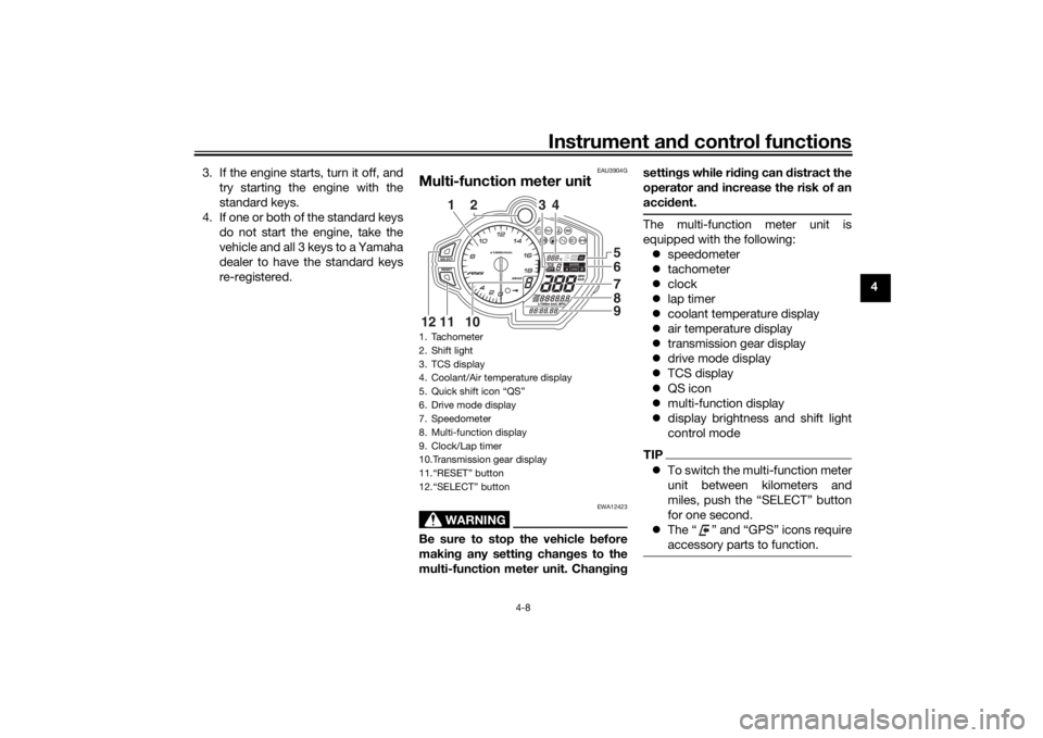
Multi-function meter unit
WARNING
EWA12423
Be sure to stop the vehicle before
making any setting changes to the
multi-function meter unit. Changing settings while riding can distract the
operator and increase the risk of an
accident.
The multi-function meter unit is
equipped with the following:
speedometer
tachometer
clock
lap timer
coolant temperature display
air temperature display
transmission gear display
drive mode display
TCS display
QS icon
multi-function display
display brightness and shift light
control modeTIPTo switch the multi-function meter
unit between kilometers and
miles, push the “SELECT” button
for one second.
The “ ” and “GPS” icons require
accessory parts to function.
1. Tachometer
2. Shift light
3. TCS display
4. Coolant/Air temperature display
5. Quick shift icon “QS”
6. Drive mode display
7. Speedometer
8. Multi-function display
9. Clock/Lap timer
10.Transmission gear display
11.“RESET” button
12.“SELECT” button
65789
2
3
4
10
11
12
1
UBN6E3E0.book Page 8 Wednesday, September 25, 2019 3:31 PM
Page 28 of 112
Instrument and control functions
4-9
4 Speed
ometer
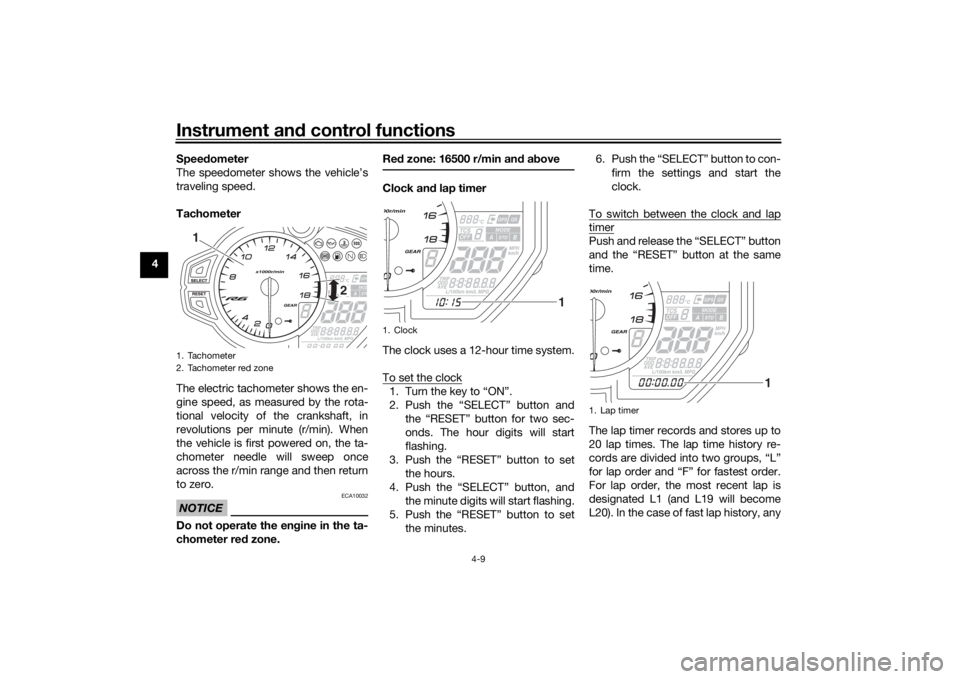
The speedometer shows the vehicle’s
traveling speed.
Tachometer
The electric tachometer shows the en-
gine speed, as measured by the rota-
tional velocity of the crankshaft, in
revolutions per minute (r/min). When
the vehicle is first powered on, the ta-
chometer needle will sweep once
across the r/min range and then return
to zero.
NOTICE
ECA10032
Do not operate the en gine in the ta-
chometer red zone. Re
d zone: 16500 r/min an d a bove
Clock an d lap timer
The clock uses a 12-hour time system.
To set the clock1. Turn the key to “ON”.
2. Push the “SELECT” button and the “RESET” button for two sec-
onds. The hour digits will start
flashing.
3. Push the “RESET” button to set the hours.
4. Push the “SELECT” button, and the minute digits will start flashing.
5. Push the “RESET” button to set the minutes. 6. Push the “SELECT” button to con-
firm the settings and start the
clock.
To switch between the clock and lap
timerPush and release the “SELECT” button
and the “RESET” button at the same
time.
The lap timer records and stores up to
20 lap times. The lap time history re-
cords are divided into two groups, “L”
for lap order and “F” for fastest order.
For lap order, the most recent lap is
designated L1 (and L19 will become
L20). In the case of fast lap history, any
1. Tachometer
2. Tachometer red zone
2
1
1. Clock
1
1. Lap timer
1
UBN6E2E0.book Page 9 Friday, December 7, 2018 2:56 PM
Page 29 of 112
Instrument and control functions
4-10
4
new fast lap within the top 20 will be in-
serted and the previous F20 will be
pushed out of the history.
To use the lap timer
1. Push the “RESET” button for one
second to set the lap timer to the
counting-ready state (the colon “:”
and period “.” will flash).
2. Push the pass switch “ ” to start the lap timer.
3. Push the pass switch “ ” to mark the start of each new lap.
4. Push the “SELECT” button to stop the lap timer.
5. Push the “SELECT” button again to reset the lap timer (or push the
“RESET” button for one second to
reset the lap timer and set it to the
counting-ready state).
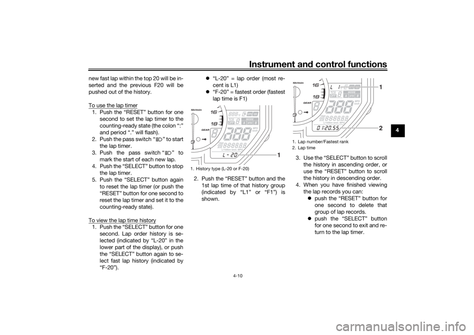
To view the lap time history1. Push the “SELECT” button for one second. Lap order history is se-
lected (indicated by “L-20” in the
lower part of the display), or push
the “SELECT” button again to se-
lect fast lap history (indicated by
“F-20”).
“L-20” = lap order (most re-
cent is L1)
“F-20” = fastest order (fastest
lap time is F1)
2. Push the “RESET” button and the 1st lap time of that history group
(indicated by “L1” or “F1”) is
shown. 3. Use the “SELECT” button to scroll
the history in ascending order, or
use the “RESET” button to scroll
the history in descending order.
4. When you have finished viewing the lap records you can: push the “RESET” button for
one second to delete that
group of lap records.
push the “SELECT” button
for one second to exit and re-
turn to the lap timer.
1. History type (L-20 or F-20)
1
1. Lap number/Fastest rank
2. Lap time
12
UBN6E2E0.book Page 10 Friday, December 7, 2018 2:56 PM
Page 30 of 112
Instrument and control functions
4-11
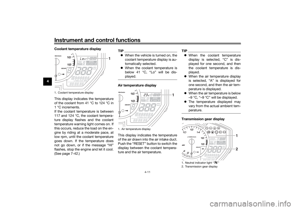
4Coolant temperature display
This display indicates the temperature
of the coolant from 41 °C to 124 °C in
1 °C increments.
If the coolant temperature is between
117 and 124 °C, the coolant tempera-
ture display flashes and the coolant
temperature warning light comes on. If
this occurs, reduce the load on the en-
gine by riding at a moderate pace, at
low rpm, until the coolant temperature
goes down. If the temperature does
not go down, or if the message “HI”
flashes, stop the engine and let it cool.
(See page 7-42.)
TIP
When the vehicle is turned on, the
coolant temperature display is au-
tomatically selected.
When the coolant temperature is
below 41 °C, “Lo” will be dis-
played.Air temperature display
This display indicates the temperature
of the air drawn into the air intake duct.
Push the “RESET” button to switch the
display between the coolant tempera-
ture and the air temperature.
TIPWhen the coolant temperature
display is selected, “C” is dis-
played for one second, and then
the coolant temperature is dis-
played.
When the air temperature display
is selected, “A” is displayed for
one second, and then the air tem-
perature is displayed.
When the air temperature is below
–9 °C, “–9 °C” will be displayed.
The temperature displayed may
vary from the actual ambient tem-
perature.Transmission gear display
1. Coolant temperature display
1
1. Air temperature display
1
1. Neutral indicator light “ ”
2. Transmission gear display
2 1
UBN6E3E0.book Page 11 Wednesday, September 25, 2019 3:32 PM
Page 32 of 112

Instrument and control functions
4-13
4 The multi-function display is equipped
with the following:
odometer
two tripmeters
fuel reserve tripmeter
instantaneous fuel consumption
average fuel consumption
total fuel used
Navi gatin g the multi-function dis-
play
Push the “SELECT” button to change
between the odometer “ODO”, tripme-
ters “TRIP 1” and “TRIP 2”, instanta-
neous fuel consumption “km/L”,
“L/100 km” or “MPG”, average fuel
consumption “AVE _ _ _._ km/L”, “AVE
_ _ _._ L/100 km” or “AVE _ _ _._ MPG”,
and total fuel used “_ _._” in the follow-
ing order:
ODO → TRIP 1 → TRIP 2 → km/L,
L/100 km or MPG → AVE _ _ _._ km/L,
AVE _ _ _._ L/100 km or AVE _ _ _._
MPG → _ _._ → ODO
O dometer an d tripmeters
The odometer shows the total distance
traveled by the vehicle. The tripmeters show the distance trav-
eled since they were last reset. To reset
a tripmeter, push the “RESET” button
for one second.
TIP
The odometer will lock at 999999.
The tripmeters will reset and con-
tinue counting after 9999.9 is
reached.Fuel reserve tripmeter
If the fuel level warning light comes on,
the display will automatically change to
the fuel reserve tripmeter “TRIP F” and
start counting the distance traveled
from that point. In this case, push the
“SELECT” button to switch the display
in the following order:
TRIP F → km/L, L/100 km or MPG →
AVE _ _ _._ km/L, AVE _ _ _._ L/100 km
or AVE _ _ _._ MPG → _ _._ → ODO →
TRIP 1 → TRIP 2 → TRIP F
TIPIf you do not reset the fuel reserve trip-
meter manually, after refueling and
traveling 5 km (3 mi), it will reset auto-
matically and disappear from the dis-
play.Instantaneous fuel consumption
This function calculates the fuel con-
sumption under current riding condi-
tions.
The instantaneous fuel consumption
display can be set to either “km/L” or
“L/100 km” when using kilometers, or
to “MPG” when using miles. When us-1. Instantaneous fuel consumption display
1
UBN6E2E0.book Page 13 Friday, December 7, 2018 2:56 PM
Page 33 of 112

Instrument and control functions
4-14
4
ing kilometers, push the “SELECT”
button for one second to switch be-
tween “km/L” and “L/100 km”.
“km/L”: The distance that can be
traveled on 1.0 L of fuel under the
current riding conditions is shown.
“L/100 km”: The amount of fuel
necessary to travel 100 km under
the current riding conditions is
shown.
“MPG”: The distance that can be
traveled on 1.0 US gal of fuel un-
der the current riding conditions is
shown.
TIPIf traveling at speeds under 20 km/h
(12 mi/h), “_ _ _._” is displayed.
Avera ge fuel consumption
This function calculates the average
fuel consumption since it was last re-
set.
The average fuel consumption display
can be set to either “AVE _ _ _._ km/L”
or “AVE _ _ _._ L/100 km” when using
kilometers, or to “AVE _ _ _._ MPG”
when using miles. When using kilome-
ters, push the “SELECT” button for one
second to switch between “AVE _ _ _._
km/L” and “AVE _ _ _._ L/100 km”. “AVE _ _ _._ km/L”: The average
distance that can be traveled on
1.0 L of fuel is shown.
“AVE _ _ _._ L/100 km”: The aver-
age amount of fuel necessary to
travel 100 km is shown.
“AVE _ _ _._ MPG”: The average
distance that can be traveled on
1.0 US gal of fuel is shown.
TIPTo reset the average fuel con-
sumption display, push the “RE-
SET” button for one second.
After resetting the average fuel
consumption display, “_ _ _._” will
be shown until the vehicle has
traveled 1 km (0.6 mi).Total fuel use d
This display shows the total amount of
fuel that has been used since it was
last reset.
1. Average fuel consumption display
1
1. Total fuel used display
1
UBN6E2E0.book Page 14 Friday, December 7, 2018 2:56 PM
Page 34 of 112
Instrument and control functions
4-15
4 When using kilometers, this figure is
shown in liters. When using miles, this
figure is shown in gallons.
To reset the total fuel used display,
push the “RESET” button for one sec-
ond.
TIPAfter the total fuel used display is reset,
“_ _ . _” will be shown until the vehicle
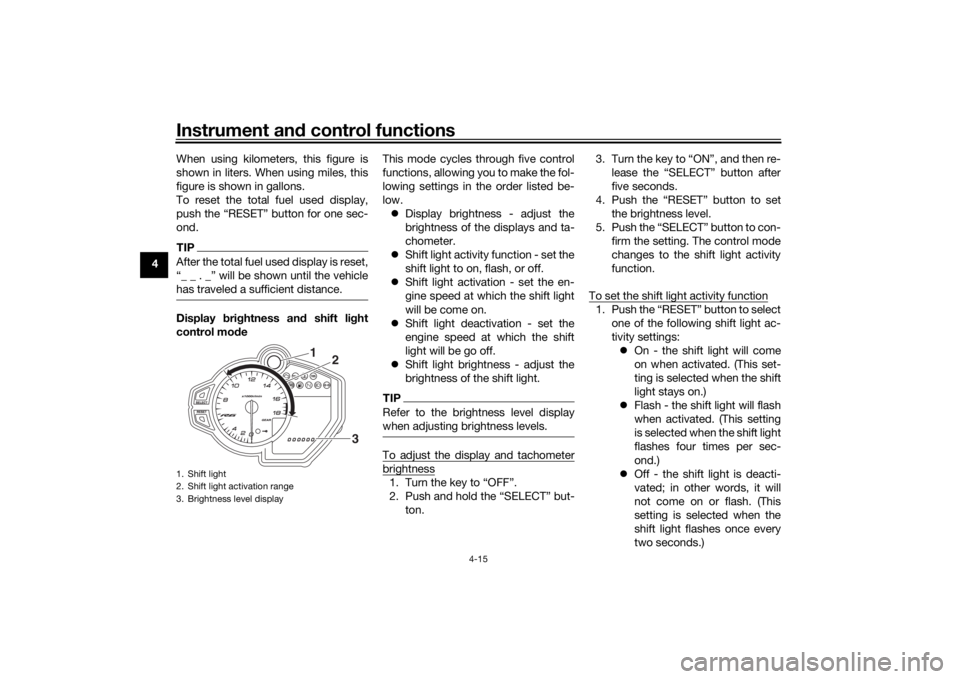
has traveled a sufficient distance.Display
bri ghtness an d shift li ght
control mo de This mode cycles through five control
functions, allowing you to make the fol-
lowing settings in the order listed be-
low.
Display brightness - adjust the
brightness of the displays and ta-
chometer.
Shift light activity function - set the
shift light to on, flash, or off.
Shift light activation - set the en-
gine speed at which the shift light
will be come on.
Shift light deactivation - set the
engine speed at which the shift
light will be go off.
Shift light brightness - adjust the
brightness of the shift light.
TIPRefer to the brightness level display
when adjusting brightness levels.To adjust the display and tachometerbrightness1. Turn the key to “OFF”.
2. Push and hold the “SELECT” but-
ton. 3. Turn the key to “ON”, and then re-
lease the “SELECT” button after
five seconds.
4. Push the “RESET” button to set the brightness level.
5. Push the “SELECT” button to con- firm the setting. The control mode
changes to the shift light activity
function.
To set the shift light activity function
1. Push the “RESET” button to select one of the following shift light ac-
tivity settings: On - the shift light will come
on when activated. (This set-
ting is selected when the shift
light stays on.)
Flash - the shift light will flash
when activated. (This setting
is selected when the shift light
flashes four times per sec-
ond.)
Off - the shift light is deacti-
vated; in other words, it will
not come on or flash. (This
setting is selected when the
shift light flashes once every
two seconds.)
1. Shift light
2. Shift light activation range
3. Brightness level display
1
2
3
UBN6E2E0.book Page 15 Friday, December 7, 2018 2:56 PM
Page 35 of 112

Instrument and control functions
4-16
4
2. Push the “SELECT” button to con-
firm the selected shift light activity.
The control mode changes to the
shift light activation point setting
function.
To set the shift light activation point
TIPThe shift light activation point can be
set between 10000 r/min and 18000
r/min. From 10000 r/min to 13000
r/min, the shift light can be set in incre-
ments of 500 r/min. From 13000 r/min
to 18000 r/min, the shift light can be set
in increments of 200 r/min.1. Push the “RESET” button to set the activation point engine speed.
2. Push the “SELECT” button to con- firm the setting. The control mode
changes to the shift light deactiva-
tion point setting function.
To set the shift light deactivation pointTIPThe deactivation range is the same as
the activation range. However, be sure
to set the deactivation point to a higher engine speed than the activation point,
otherwise the shift light will not come
on.
1. Push the “RESET” button to set
the deactivation point engine
speed.
2. Push the “SELECT” button to con- firm the setting. The control mode
changes to the shift light bright-
ness function.
To adjust the shift light brightness1. Push the “RESET” button to set the shift light brightness level.
2. Push the “SELECT” button to con- firm the setting and exit the dis-
play brightness and shift light
control mode.
EAU12822
Clutch leverThe clutch lever is located on the left
side of the handlebar. To disengage
the clutch, pull the lever toward the
handlebar grip. To engage the clutch,
release the lever. The lever should be
pulled rapidly and released slowly for
smooth clutch operation.
The clutch lever is equipped with a
clutch switch, which is part of the igni-
tion circuit cut-off system. (See page
4-30.)1. Clutch lever
1
UBN6E2E0.book Page 16 Friday, December 7, 2018 2:56 PM