turn signal YAMAHA YZF-R6 2020 Owners Manual
[x] Cancel search | Manufacturer: YAMAHA, Model Year: 2020, Model line: YZF-R6, Model: YAMAHA YZF-R6 2020Pages: 112, PDF Size: 5.44 MB
Page 9 of 112

Safety information
1-2
1
Many accidents involve inexperi-
enced operators. In fact, many op-
erators who have been involved in
accidents do not even have a cur-
rent motorcycle license.
• Make sure that you are qualified and that you only lend your mo-
torcycle to other qualified oper-
ators.
• Know your skills and limits. Staying within your limits may
help you to avoid an accident.
• We recommend that you prac- tice riding your motorcycle
where there is no traffic until you
have become thoroughly famil-
iar with the motorcycle and all of
its controls.
Many accidents have been
caused by error of the motorcycle
operator. A typical error made by
the operator is veering wide on a
turn due to excessive speed or un-
dercornering (insufficient lean an-
gle for the speed).
• Always obey the speed limit and never travel faster than warrant-
ed by road and traffic condi-
tions. • Always signal before turning or
changing lanes. Make sure that
other motorists can see you.
The posture of the operator and
passenger is important for proper
control.
• The operator should keep both hands on the handlebar and
both feet on the operator foot-
rests during operation to main-
tain control of the motorcycle.
• The passenger should always hold onto the operator, the seat
strap or grab bar, if equipped,
with both hands and keep both
feet on the passenger footrests.
Never carry a passenger unless
he or she can firmly place both
feet on the passenger footrests.
Never ride under the influence of
alcohol or other drugs.
This motorcycle is designed for
on-road use only. It is not suitable
for off-road use. Protective Apparel
The majority of fatalities from motorcy-
cle accidents are the result of head in-
juries. The use of a safety helmet is the
single most critical factor in the pre-
vention or reduction of head injuries.
Always wear an approved helmet.
Wear a face shield or goggles.
Wind in your unprotected eyes
could contribute to an impairment
of vision that could delay seeing a
hazard.
The use of a jacket, heavy boots,
trousers, gloves, etc., is effective
in preventing or reducing abra-
sions or lacerations.
Never wear loose-fitting clothes,
otherwise they could catch on the
control levers, footrests, or wheels
and cause injury or an accident.
Always wear protective clothing
that covers your legs, ankles, and
feet. The engine or exhaust sys-
tem become very hot during or af-
ter operation and can cause
burns.
A passenger should also observe
the above precautions.
UBN6E2E0.book Page 2 Friday, December 7, 2018 2:56 PM
Page 12 of 112

Safety information
1-5
1operator and may limit control
ability, therefore, such accesso-
ries are not recommended.
Use caution when adding electri-
cal accessories. If electrical ac-
cessories exceed the capacity of
the motorcycle’s electrical sys-
tem, an electric failure could re-
sult, which could cause a
dangerous loss of lights or engine
power.
Aftermarket Tires an d Rims
The tires and rims that came with your
motorcycle were designed to match
the performance capabilities and to
provide the best combination of han-
dling, braking, and comfort. Other
tires, rims, sizes, and combinations
may not be appropriate. See page 7-21
for tire specifications and for informa-
tion on servicing and replacing your
tires.
Transportin g the Motorcycle
Be sure to observe following instruc-
tions before transporting the motorcy-
cle in another vehicle.
Remove all loose items from the
motorcycle.
Check that the fuel cock (if
equipped) is in the off position and
that there are no fuel leaks.
Shift the transmission into gear
(for models with a manual trans-
mission).
Secure the motorcycle with tie-
downs or suitable straps that are
attached to solid parts of the mo-
torcycle, such as the frame or up-
per front fork triple clamp (and not,
for example, to rubber-mounted
handlebars or turn signals, or
parts that could break). Choose
the location for the straps carefully
so the straps will not rub against
painted surfaces during transport.
The suspension should be com-
pressed somewhat by the tie-
downs, if possible, so that the mo-
torcycle will not bounce exces-
sively during transport.
UBN6E2E0.book Page 5 Friday, December 7, 2018 2:56 PM
Page 22 of 112

Instrument and control functions
4-3
4
TIPIf the steering will not lock, try turning
the handlebars back to the right slight-
ly.To unlock the steeringFrom the “LOCK” position, push the
key in and turn it to “OFF”.
EAU59680
(Parkin g)
The hazard lights and turn signal lights
can be turned on, but all other electri-
cal systems are off. The key can be re-
moved.
The steering must be locked before the
key can be turned to “ ”.
NOTICE
ECA20760
Usin g the hazar d o r t ur n s i gnal li ghts
for an exten ded len gth of time may
cause the battery to d ischarge.
EAU66055
Han dle bar switchesLeft
1. Push.
2. Turn.12
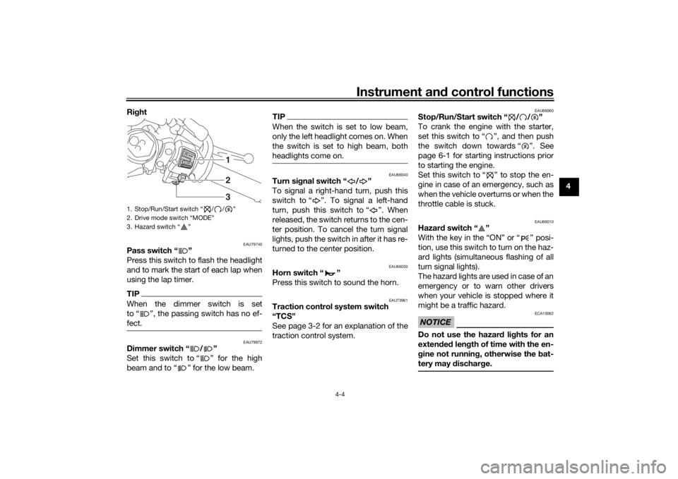
1. Dimmer switch “ / ”
2. Pass switch “ ”
3. Traction control system switch “TCS”
4. Turn signal switch “ / ”
5. Horn switch “ ”
5
4
2
3
1
UBN6E2E0.book Page 3 Friday, December 7, 2018 2:56 PM
Page 23 of 112

Instrument and control functions
4-4
4
Ri
ght
EAU79740
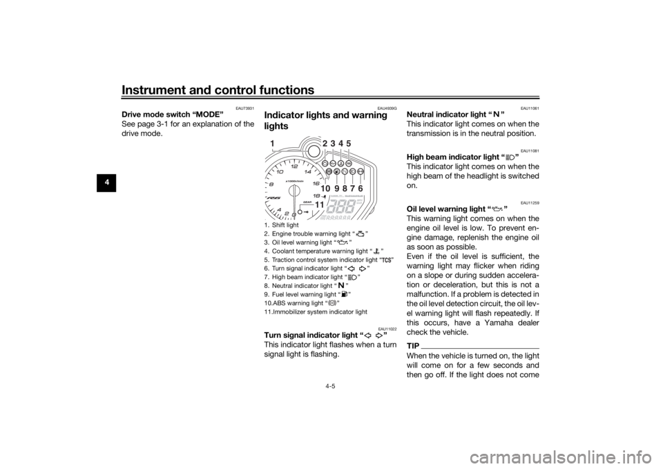
Pass switch “ ”
Press this switch to flash the headlight
and to mark the start of each lap when
using the lap timer.TIPWhen the dimmer switch is set
to “ ”, the passing switch has no ef-
fect.
EAU79872
Dimmer switch “ / ”
Set this switch to “ ” for the high
beam and to “ ” for the low beam.
TIPWhen the switch is set to low beam,
only the left headlight comes on. When
the switch is set to high beam, both
headlights come on.
EAU66040
Turn si gnal switch “ / ”
To signal a right-hand turn, push this
switch to “ ”. To signal a left-hand
turn, push this switch to “ ”. When
released, the switch returns to the cen-
ter position. To cancel the turn signal
lights, push the switch in after it has re-
turned to the center position.
EAU66030
Horn switch “ ”
Press this switch to sound the horn.
EAU73961
Traction control system switch
“TCS”
See page 3-2 for an explanation of the
traction control system.
EAU66060
Stop/Run/Start switch “ / / ”
To crank the engine with the starter,
set this switch to “ ”, and then push
the switch down towards “ ”. See
page 6-1 for starting instructions prior
to starting the engine.
Set this switch to “ ” to stop the en-
gine in case of an emergency, such as
when the vehicle overturns or when the
throttle cable is stuck.
EAU66010
Hazar d switch “ ”
With the key in the “ON” or “ ” posi-
tion, use this switch to turn on the haz-
ard lights (simultaneous flashing of all
turn signal lights).
The hazard lights are used in case of an
emergency or to warn other drivers
when your vehicle is stopped where it
might be a traffic hazard.NOTICE
ECA10062
Do not use the hazar d lig hts for an
exten ded len gth of time with the en-
g ine not runnin g, otherwise the bat-
tery may d ischarge.
1. Stop/Run/Start switch “ / / ”
2. Drive mode switch “MODE”
3. Hazard switch “ ”
231
UBN6E2E0.book Page 4 Friday, December 7, 2018 2:56 PM
Page 24 of 112

Instrument and control functions
4-5
4
EAU73931
Drive mo de switch “MODE”
See page 3-1 for an explanation of the
drive mode.
EAU4939G
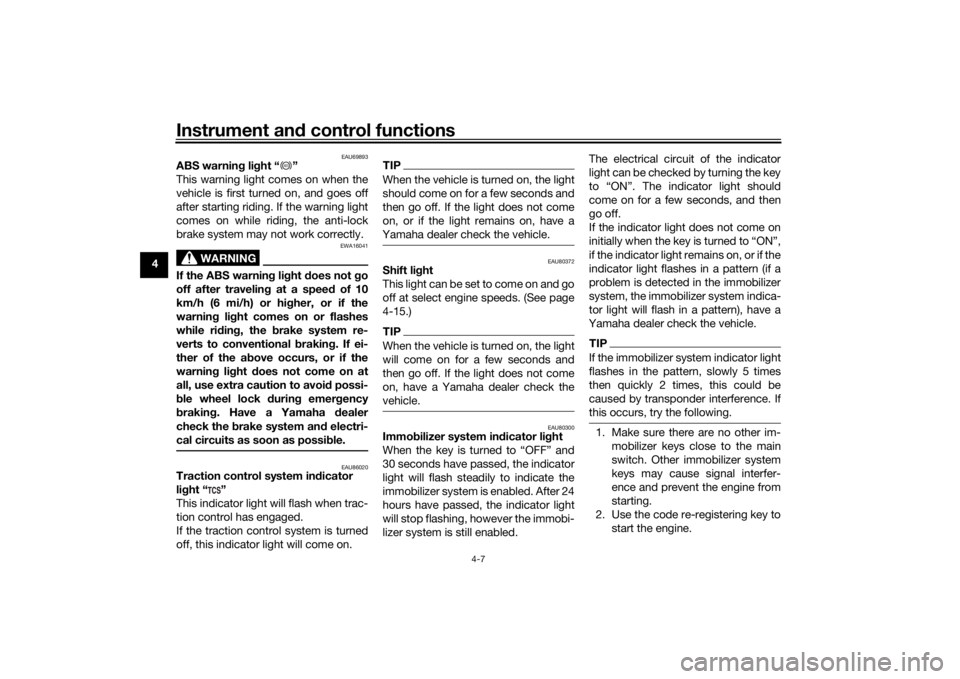
In dicator li ghts an d warnin g
li g hts
EAU11022
Turn si gnal in dicator li ght “ ”
This indicator light flashes when a turn
signal light is flashing.
EAU11061
Neutral in dicator li ght “ ”
This indicator light comes on when the
transmission is in the neutral position.
EAU11081
Hi gh beam in dicator li ght “ ”
This indicator light comes on when the
high beam of the headlight is switched
on.
EAU11259
Oil level warnin g li ght “ ”
This warning light comes on when the
engine oil level is low. To prevent en-
gine damage, replenish the engine oil
as soon as possible.
Even if the oil level is sufficient, the
warning light may flicker when riding
on a slope or during sudden accelera-
tion or deceleration, but this is not a
malfunction. If a problem is detected in
the oil level detection circuit, the oil lev-
el warning light will flash repeatedly. If
this occurs, have a Yamaha dealer
check the vehicle.TIPWhen the vehicle is turned on, the light
will come on for a few seconds and
then go off. If the light does not come
1. Shift light
2. Engine trouble warning light “ ”
3. Oil level warning light “ ”
4. Coolant temperature warning light “ ”
5. Traction control system indicator light “ ”
6. Turn signal indicator light “ ”
7. High beam indicator light “ ”
8. Neutral indicator light “ ”
9. Fuel level warning light “ ”
10.ABS warning light “ ”
11.Immobilizer system indicator light
234510
9
8
7
6
11
1
ABS
UBN6E2E0.book Page 5 Friday, December 7, 2018 2:56 PM
Page 26 of 112

Instrument and control functions
4-7
4
EAU69893
ABS warnin g li ght “ ”
This warning light comes on when the
vehicle is first turned on, and goes off
after starting riding. If the warning light
comes on while riding, the anti-lock
brake system may not work correctly.
WARNING
EWA16041
If the ABS warnin g li ght does not go
off after travelin g at a speed of 10
km/h (6 mi/h) or hi gher, or if the
warnin g li ght comes on or flashes
while ri din g, the b rake system re-
verts to conventional brakin g. If ei-
ther of the ab ove occurs, or if the
warnin g li ght does not come on at
all, use extra caution to avoi d possi-
b le wheel lock during emer gency
b rakin g. Have a Yamaha d ealer
check the brake system an d electri-
cal circuits as soon as possi ble.
EAU86020
Traction control system in dicator
li g ht “ ”
This indicator light will flash when trac-
tion control has engaged.
If the traction control system is turned
off, this indicator light will come on.
TIPWhen the vehicle is turned on, the light
should come on for a few seconds and
then go off. If the light does not come
on, or if the light remains on, have a
Yamaha dealer check the vehicle.
EAU80372
Shift li ght
This light can be set to come on and go
off at select engine speeds. (See page
4-15.)TIPWhen the vehicle is turned on, the light
will come on for a few seconds and
then go off. If the light does not come
on, have a Yamaha dealer check the
vehicle.
EAU80300
Immo bilizer system in dicator li ght
When the key is turned to “OFF” and
30 seconds have passed, the indicator
light will flash steadily to indicate the
immobilizer system is enabled. After 24
hours have passed, the indicator light
will stop flashing, however the immobi-
lizer system is still enabled. The electrical circuit of the indicator
light can be checked by turning the key
to “ON”. The indicator light should
come on for a few seconds, and then
go off.
If the indicator light does not come on
initially when the key is turned to “ON”,
if the indicator light remains on, or if the
indicator light flashes in a pattern (if a
problem is detected in the immobilizer
system, the immobilizer system indica-
tor light will flash in a pattern), have a
Yamaha dealer check the vehicle.
TIPIf the immobilizer system indicator light
flashes in the pattern, slowly 5 times
then quickly 2 times, this could be
caused by transponder interference. If
this occurs, try the following.1. Make sure there are no other im- mobilizer keys close to the main
switch. Other immobilizer system
keys may cause signal interfer-
ence and prevent the engine from
starting.
2. Use the code re-registering key to start the engine.
ABS
UBN6E2E0.book Page 7 Friday, December 7, 2018 2:56 PM
Page 94 of 112

Periodic maintenance an d a djustment
7-37
7
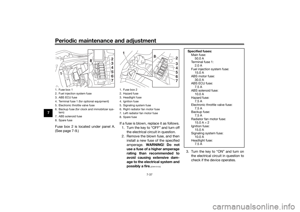
Fuse box 2 is located under panel A.
(See page 7-9.) If a fuse is blown, replace it as follows.
1. Turn the key to “OFF” and turn off the electrical circuit in question.
2. Remove the blown fuse, and then install a new fuse of the specified
amperage. WARNING! Do not
use a fuse of a hi gher ampera ge
ratin g than recommen ded to
avoi d causin g extensive d am-
a g e to the electrical system an d
possi bly a fire.
[EWA15132]
3. Turn the key to “ON” and turn on
the electrical circuit in question to
check if the device operates.
1. Fuse box 1
2. Fuel injection system fuse
3. ABS ECU fuse
4. Terminal fuse 1 (for optional equipment)
5. Electronic throttle valve fuse
6. Backup fuse (for clock and immobilizer sys-tem)
7. ABS solenoid fuse
8. Spare fuse
2
1
345
8
67
1. Fuse box 2
2. Hazard fuse
3. Headlight fuse
4. Ignition fuse
5. Signaling system fuse
6. Right radiator fan motor fuse
7. Left radiator fan motor fuse
8. Spare fuse
2
1
345
8
67
Specifie d fuses:
Main fuse:
50.0 A
Te r m i n a l f u s e 1 :
2.0 A
Fuel injection system fuse: 15.0 A
ABS motor fuse: 30.0 A
ABS ECU fuse:
7.5 A
ABS solenoid fuse: 10.0 A
Hazard fuse: 7.5 A
Electronic throttle valve fuse:
7.5 A
Backup fuse: 7.5 A
Radiator fan motor fuse: 15.0 A × 2
Ignition fuse:
15.0 A
Signaling system fuse: 10.0 A
Headlight fuse: 7.5 A
UBN6E2E0.book Page 37 Friday, December 7, 2018 2:56 PM
Page 105 of 112

Specifications
9-2
9
Manufacturer/model:DUNLOP/SPORTMAX D214
Manufacturer/model: BRIDGESTONE/BATTLAX HYPERSPORT S21RLoa din g:Maximum load:
185 kg (408 lb)
(Total weight of rider, passenger, cargo and
accessories)Front brake:Type:
Hydraulic dual disc brakeRear brake:Type:
Hydraulic single disc brakeFront suspension:Type:Telescopic forkRear suspension:Type:
Swingarm (link suspension)Electrical system:System voltage:12 VBattery:Model:YTZ7S
Voltage, capacity: 12 V, 6.0 Ah (10 HR)Bul b watta ge:Headlight:
LED Brake/tail light:
LED
Front turn signal light: LED
Rear turn signal light:
LED
Auxiliary light: LED
License plate light: 5.0 W
UBN6E2E0.book Page 2 Friday, December 7, 2018 2:56 PM
Page 110 of 112

Index
11-2
11
Stop/Run/Start switch ............................ 4-4
Storage ................................................... 8-3
Supporting the motorcycle ................... 7-39
Swingarm pivots, lubricating ................ 7-33TThrottle grip and cable, checking and
lubricating ........................................... 7-31
Throttle grip free play, checking ........... 7-21
Tires ...................................................... 7-21
Tool kit .................................................... 7-2
Traction control system .......................... 3-2
Traction control system indicator light ... 4-7
Traction control system switch ............... 4-4
Troubleshooting .................................... 7-39
Troubleshooting chart........................... 7-41
Turn signal indicator light ....................... 4-5
Turn signal switch ................................... 4-4VValve clearance..................................... 7-21
Vehicle identification number ............... 10-1
Vehicle lights ......................................... 7-38WWheel bearings, checking..................... 7-35
Wheels .................................................. 7-24YYamalube .............................................. 7-18
UBN6E2E0.book Page 2 Friday, December 7, 2018 2:56 PM