Front wheel YAMAHA YZF-R7 2022 Owners Manual
[x] Cancel search | Manufacturer: YAMAHA, Model Year: 2022, Model line: YZF-R7, Model: YAMAHA YZF-R7 2022Pages: 100, PDF Size: 3.78 MB
Page 6 of 100

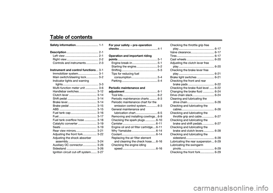
Table of contentsSafety information ............................ 1-1
Description ....................................... 2-1
Left view ......................................... 2-1
Right view ....................................... 2-2
Controls and instruments ............... 2-3
Instrument an d control functions ... 3-1
Immobilizer system......................... 3-1
Main switch/steering lock............... 3-2
Indicator lights and warning lights............................................ 3-3
Multi-function meter unit ................ 3-6
Handlebar switches ...................... 3-12
Clutch lever .................................. 3-14
Shift pedal .................................... 3-14
Brake lever.................................... 3-14
Brake pedal .................................. 3-15
ABS .............................................. 3-15
Fuel tank cap ................................ 3-16
Fuel ............................................... 3-17
Fuel tank overflow hose ............... 3-18
Catalytic converter ....................... 3-19
Seats ............................................ 3-19
Rear view mirrors.......................... 3-21
Adjusting the front fork ................. 3-22
Adjusting the shock absorber assembly ................................... 3-24
Auxiliary DC connector ................. 3-26
Sidestand ..................................... 3-26
Ignition circuit cut-off system ....... 3-27 For your safety – pre-operation
checks
............................................... 4-1
Operation an d important ri din g
points ................................................. 5-1
Engine break-in ............................... 5-1
Starting the engine .......................... 5-2
Shifting ............................................ 5-3
Tips for reducing fuel consumption ................................ 5-4
Parking ............................................ 5-4
Perio dic maintenance an d
a d justment ........................................ 6-1
Tool kits........................................... 6-2
Periodic maintenance charts .......... 6-3
Periodic maintenance chart for the emission control system .............. 6-3
General maintenance and lubrication chart ........................... 6-5
Removing and installing cowlings... 6-9
Checking the spark plugs ............. 6-10
Canister ......................................... 6-11
Engine oil and oil filter cartridge.... 6-11
Why Yamalube .............................. 6-14
Coolant.......................................... 6-14
Replacing the air filter element and cleaning the check hose..... 6-16
Checking the engine idling
speed ......................................... 6-16 Checking the throttle grip free
play ............................................ 6-17
Valve clearance............................. 6-17
Tires .............................................. 6-17
Cast wheels .................................. 6-20
Adjusting the clutch lever free play ............................................ 6-20
Checking the brake lever free
play ............................................ 6-21
Brake light switches ..................... 6-21
Checking the front and rear brake pads ................................ 6-22
Checking the brake fluid level ...... 6-22
Changing the brake fluid .............. 6-24
Drive chain slack........................... 6-24
Cleaning and lubricating the drive chain ................................. 6-26
Checking and lubricating the cables ........................................ 6-26
Checking and lubricating the
throttle grip and cable ............... 6-27
Checking and lubricating the brake and shift pedals............... 6-27
Checking and lubricating the brake and clutch levers ............. 6-28
Checking and lubricating the
sidestand................................... 6-28
Lubricating the rear suspension ... 6-29
Lubricating the swingarm pivots......................................... 6-29
Checking the front fork ................. 6-29UBEBE0E0.book Page 1 Monday, July 5, 2021 2:26 PM
Page 29 of 100

Instrument and control functions
3-14
3
EAU12823
Clutch leverTo disengage the drivetrain from the
engine, such as when shifting gears,
pull the clutch lever toward to the han-
dlebar. Release the lever to engage the
clutch and transmit power to the rear
wheel.TIPThe lever should be pulled rapidly and
released slowly for smooth shifting.
(See page 5-3.)
EAU12876
Shift pedalThe shift pedal is located on the left
side of the motorcycle. To shift the
transmission to a higher gear, move
the shift pedal up. To shift the trans-
mission to a lower gear, move the shift
pedal down. (See page 5-3.)
EAU93080
Brake leverThe brake lever is located on the right
side of the handlebar. To apply the
front brake, pull the lever toward the
throttle grip.
The brake lever is equipped with a
brake lever position adjusting knob. To
adjust the distance between the brake
lever and the throttle grip, turn the ad-
justing knob while holding the lever
pushed away from the throttle grip.
Turn the adjusting knob in direction (a)
to increase the distance. Turn the ad-
justing knob in direction (b) to decrease
the distance.
1. Clutch lever
1 1 1
1. Shift pedal
1 1 1
1. Brake lever
2. Distance
3. Brake lever position adjusting knob
1 1 12 2
3 3
(a) (a) (a)
(b) (b) (b)
UBEBE0E0.book Page 14 Monday, July 5, 2021 2:26 PM
Page 30 of 100

Instrument and control functions
3-15
3
EAU12944
Brake pedalThe brake pedal is located on the right
side of the motorcycle. To apply the
rear brake, press down on the brake
pedal.
EAU93090
ABSThe Yamaha ABS (Anti-lock Brake
System) features a dual electronic con-
trol system, which acts on the front and
rear brakes independently.
Operate the brakes with ABS as you
would conventional brakes. If the ABS
is activated, a pulsating sensation may
be felt at the brake lever or brake ped-
al. In this situation, continue to apply
the brakes and let the ABS work; do
not “pump” the brakes as this will re-
duce braking effectiveness.
WARNING
EWA16051
Always keep a sufficient distance
from the vehicle ahead to match the
riding speed even with ABS. The ABS performs best with
long braking distances.
On certain surfaces, such as
rough or gravel roads, the brak-
ing distance may be longer with
the ABS than without.The ABS is monitored by an ECU,
which will revert the system to conven-
tional braking if a malfunction occurs.
TIPThe ABS performs a self-diagnos-
tic test each time the vehicle first
starts off after the key is turned to
“ON” and the vehicle has traveled
at a speed of 5 km/h (3 mi/h) or
higher. During this test, a “click-
ing” noise can be heard from the
hydraulic control unit, and if the
brake lever or brake pedal is even
slightly applied, a vibration can be
felt at the lever and pedal, but
these do not indicate a malfunc-
tion.
This ABS has a test mode which
allows the owner to experience
the pulsation at the brake lever or
brake pedal when the ABS is op-
erating. However, special tools are
required, so please consult your
Yamaha dealer.NOTICE
ECA20100
Be careful not to damage the wheel
sensor or wheel sensor rotor; other-
wise, improper performance of the
ABS will result.
1. Brake pedal
111
UBEBE0E0.book Page 15 Monday, July 5, 2021 2:26 PM
Page 31 of 100

Instrument and control functions
3-16
3
EAU13077
Fuel tank capTo open the fuel tank cap
Open the fuel tank cap lock cover, in-
sert the key, and then turn it 1/4 turn
clockwise. The lock will be released
and the fuel tank cap can be opened.
To close the fuel tank cap
With the key still inserted, push down
the fuel tank cap. Turn the key 1/4 turn
counterclockwise, remove it, and then
close the lock cover.
TIPThe fuel tank cap cannot be closed un-
less the key is in the lock. In addition,
the key cannot be removed if the cap is
not properly closed and locked.
WARNING
EWA11092
Make sure that the fuel tank cap is
properly closed after filling fuel.
Leaking fuel is a fire hazard.
1. Front wheel sensor
2. Front wheel sensor rotor
1. Rear wheel sensor
2. Rear wheel sensor rotor
1 1 12 2
1 1 1
2 2
1. Fuel tank cap lock cover
2. Unlock.
1 1 1
2 2
UBEBE0E0.book Page 16 Monday, July 5, 2021 2:26 PM
Page 55 of 100

Periodic maintenance and adjustment
6-5
6
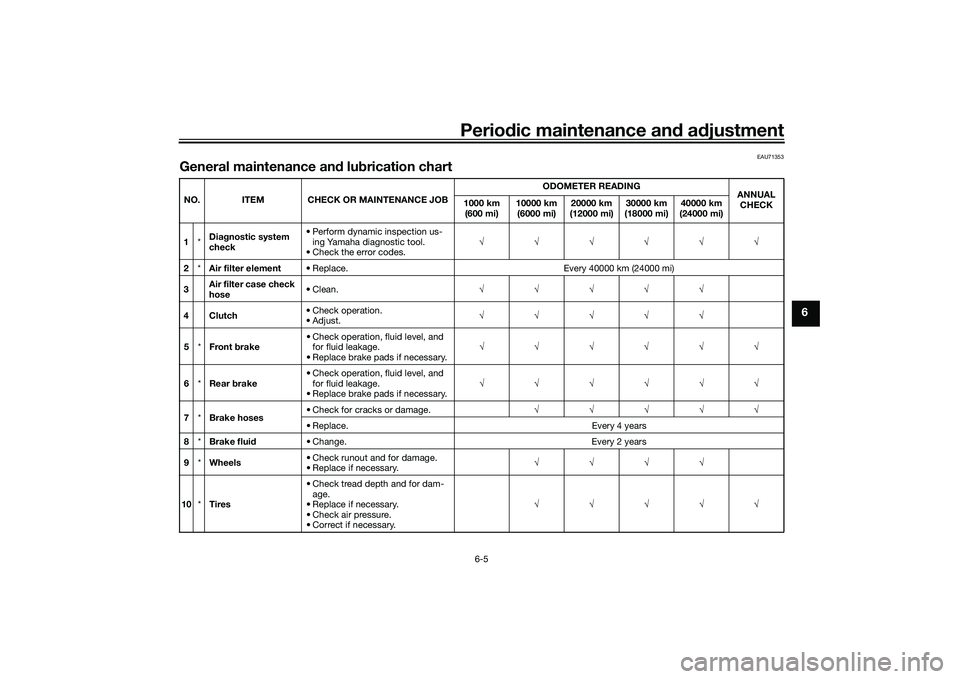
EAU71353
General maintenance and lubrication chartNO. ITEM CHECK OR MAINTENANCE JOBODOMETER READING
ANNUAL
CHECK
1000 km
(600 mi) 10000 km
(6000 mi) 20000 km
(12000 mi) 30000 km
(18000 mi) 40000 km
(24000 mi)
1 *Diagnostic system
check • Perform dynamic inspection us-
ing Yamaha diagnostic tool.
• Check the error codes. √√√√√√
2 *Air filter element • Replace. Every 40000 km (24000 mi)
3 Air filter case check
hose • Clean.
√√√√√
4Clutch • Check operation.
•Adjust.
√√√√√
5 *Front brake • Check operation, fluid level, and
for fluid leakage.
• Replace brake pads if necessary. √√√√√√
6 *Rear brake • Check operation, fluid level, and
for fluid leakage.
• Replace brake pads if necessary. √√√√√√
7 *Brake hoses • Check for cracks or damage.
√√√√√
• Replace. Every 4 years
8 *Brake fluid • Change. Every 2 years
9 *Wheels • Check runout and for damage.
• Replace if necessary. √√√√
10 *Tires • Check tread depth and for dam-
age.
• Replace if necessary.
• Check air pressure.
• Correct if necessary. √√√√√
UBEBE0E0.book Page 5 Monday, July 5, 2021 2:26 PM
Page 68 of 100

Periodic maintenance and adjustment
6-18
6weight of rider, passenger, car-
go, and accessories approved
for this model.
WARNING
EWA10512
Never overload your vehicle. Opera-
tion of an overloaded vehicle could
cause an accident.
Tire inspection
The tires must be checked before each
ride. If the center tread depth reaches
the specified limit, if the tire has a nail
or glass fragments in it, or if the side-
wall is cracked, have a Yamaha dealer
replace the tire immediately.TIPThe tire tread depth limits may differ
from country to country. Always com-
ply with the local regulations.
WARNING
EWA10472
Have a Yamaha dealer replace
excessively worn tires. Besides
being illegal, operating the vehi-
cle with excessively worn tires
decreases riding stability and
can lead to loss of control.
The replacement of all wheel
and brake-related parts, includ-
ing the tires, should be left to a
Yamaha dealer, who has the
necessary professional knowl-
edge and experience to do so.
Ride at moderate speeds after
changing a tire since the tire
surface must first be “broken
in” for it to develop its optimal
characteristics.
Cold tire air pressure:
1 person:Front:250 kPa (2.50 kgf/cm², 36 psi)
Rear: 290 kPa (2.90 kgf/cm², 42 psi)
2 persons:
Front:250 kPa (2.50 kgf/cm², 36 psi)
Rear:
290 kPa (2.90 kgf/cm², 42 psi)
Maximum load: Vehicle:
162 kg (357 lb)
The vehicle’s maximum load is the
combined weight of the rider, pas-
senger, cargo, and any accessories.
1. Tire sidewall
2. Tire tread depthMinimum tire tread depth (front and
rear): 1.6 mm (0.06 in)
UBEBE0E0.book Page 18 Monday, July 5, 2021 2:26 PM
Page 80 of 100

Periodic maintenance and adjustment
6-30
6
NOTICE
ECA10591
If any damage is found or the front
fork does not operate smoothly,
have a Yamaha dealer check or re-
pair it.
EAU23285
Checking the steeringWorn or loose steering bearings may
cause danger. Therefore, the operation
of the steering must be checked as fol-
lows at the intervals specified in the
periodic maintenance and lubrication
chart.1. Raise the front wheel off the ground. (See page 6-34.)
WARNING! To avoid injury, se-
curely support the vehicle so
there is no danger of it falling
over.
[EWA10752]
2. Hold the lower ends of the frontfork legs and try to move them for-
ward and backward. If any free
play can be felt, have a Yamaha
dealer check or repair the steer-
ing.
EAU23292
Checking the wheel bearingsThe front and rear wheel bearings must
be checked at the intervals specified in
the periodic maintenance and lubrica-
tion chart. If there is play in the wheel
hub or if the wheel does not turn
smoothly, have a Yamaha dealer
check the wheel bearings.
UBEBE0E0.book Page 30 Monday, July 5, 2021 2:26 PM
Page 84 of 100

Periodic maintenance and adjustment
6-34
6
EAU49722
Replacing a license plate light
bulb1. Remove the license plate light unitbolts.
2. Remove the license plate light bulb socket (together with the
bulb) by turning it counterclock-
wise, and then pulling it out.
3. Remove the burnt-out bulb by pulling it out. 4. Insert a new bulb into the socket.
5. Install the socket (together with
the bulb) by pushing it in, and then
turning it clockwise until it stops.
6. Place the license plate light unit in the original position, and then in-
stall the bolts.
EAU67131
Supporting the motorcycleSince this model is not equipped with a
centerstand, use maintenance stands
when removing the front or rear wheel
or when performing other maintenance
that requires the motorcycle to stand
up right.
Check that the motorcycle is in a stable
and level position before starting any
maintenance.
1. Bolt
2. Collar
3. License plate light bulb socket
4. License plate light unit
1
1
2
2
4
3
1. License plate light bulb
1
1. Maintenance stand (example)
1
UBEBE0E0.book Page 34 Monday, July 5, 2021 2:26 PM
Page 92 of 100

Specifications
8-1
8
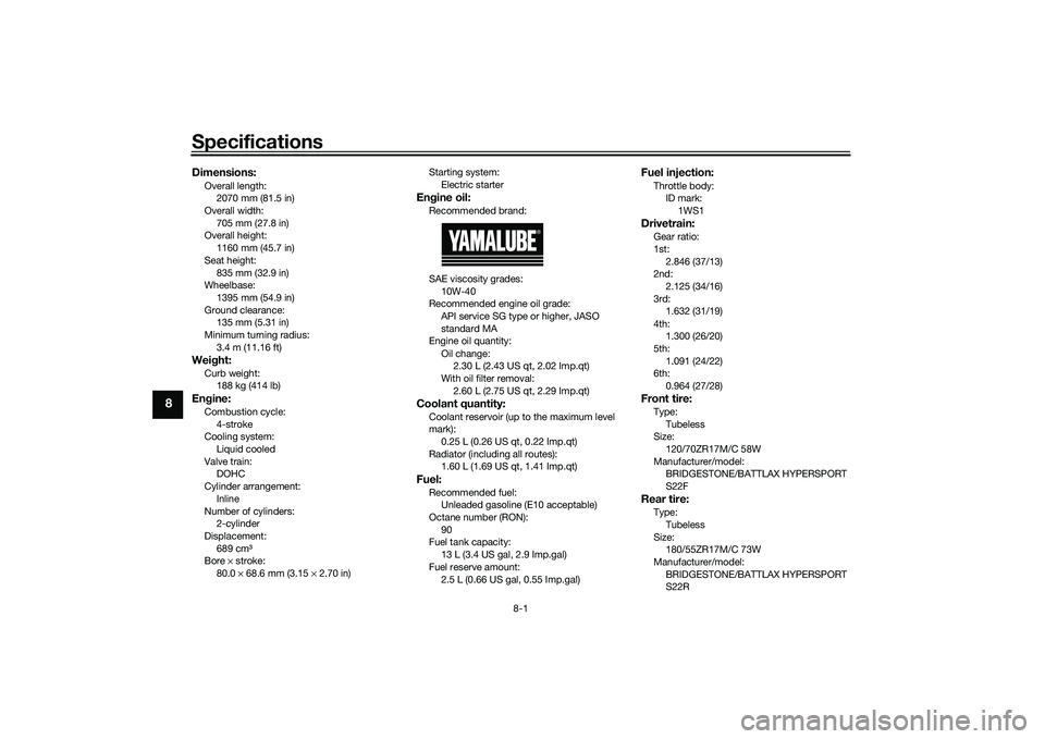
Dimensions:Overall length:2070 mm (81.5 in)
Overall width:
705 mm (27.8 in)
Overall height: 1160 mm (45.7 in)
Seat height: 835 mm (32.9 in)
Wheelbase:
1395 mm (54.9 in)
Ground clearance: 135 mm (5.31 in)
Minimum turning radius: 3.4 m (11.16 ft)Weight:Curb weight:188 kg (414 lb)Engine:Combustion cycle:
4-stroke
Cooling system: Liquid cooled
Valve train: DOHC
Cylinder arrangement:
Inline
Number of cylinders: 2-cylinder
Displacement: 689 cm³
Bore × stroke:
80.0 × 68.6 mm (3.15 × 2.70 in) Starting system:
Electric starter
Engine oil:Recommended brand:
SAE viscosity grades:10W-40
Recommended engine oil grade:
API service SG type or higher, JASO
standard MA
Engine oil quantity:
Oil change: 2.30 L (2.43 US qt, 2.02 Imp.qt)
With oil filter removal:
2.60 L (2.75 US qt, 2.29 Imp.qt)Coolant quantity:Coolant reservoir (up to the maximum level
mark):0.25 L (0.26 US qt, 0.22 Imp.qt)
Radiator (including all routes): 1.60 L (1.69 US qt, 1.41 Imp.qt)Fuel:Recommended fuel:Unleaded gasoline (E10 acceptable)
Octane number (RON): 90
Fuel tank capacity:
13 L (3.4 US gal, 2.9 Imp.gal)
Fuel reserve amount: 2.5 L (0.66 US gal, 0.55 Imp.gal)
Fuel injection:Throttle body:ID mark: 1WS1Drivetrain:Gear ratio:
1st:2.846 (37/13)
2nd:
2.125 (34/16)
3rd: 1.632 (31/19)
4th: 1.300 (26/20)
5th:
1.091 (24/22)
6th: 0.964 (27/28)Front tire:Type:
Tubeless
Size: 120/70ZR17M/C 58W
Manufacturer/model: BRIDGESTONE/BATTLAX HYPERSPORT
S22FRear tire:Type:
Tubeless
Size: 180/55ZR17M/C 73W
Manufacturer/model: BRIDGESTONE/BATTLAX HYPERSPORT
S22R
UBEBE0E0.book Page 1 Monday, July 5, 2021 2:26 PM