TOP YAMAHA YZF-R7 2022 Owners Manual
[x] Cancel search | Manufacturer: YAMAHA, Model Year: 2022, Model line: YZF-R7, Model: YAMAHA YZF-R7 2022Pages: 100, PDF Size: 3.78 MB
Page 18 of 100

Instrument and control functions
3-3
3
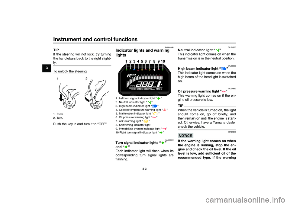
TIPIf the steering will not lock, try turning
the handlebars back to the right slight-
ly.To unlock the steeringPush the key in and turn it to “OFF”.
EAU4939R
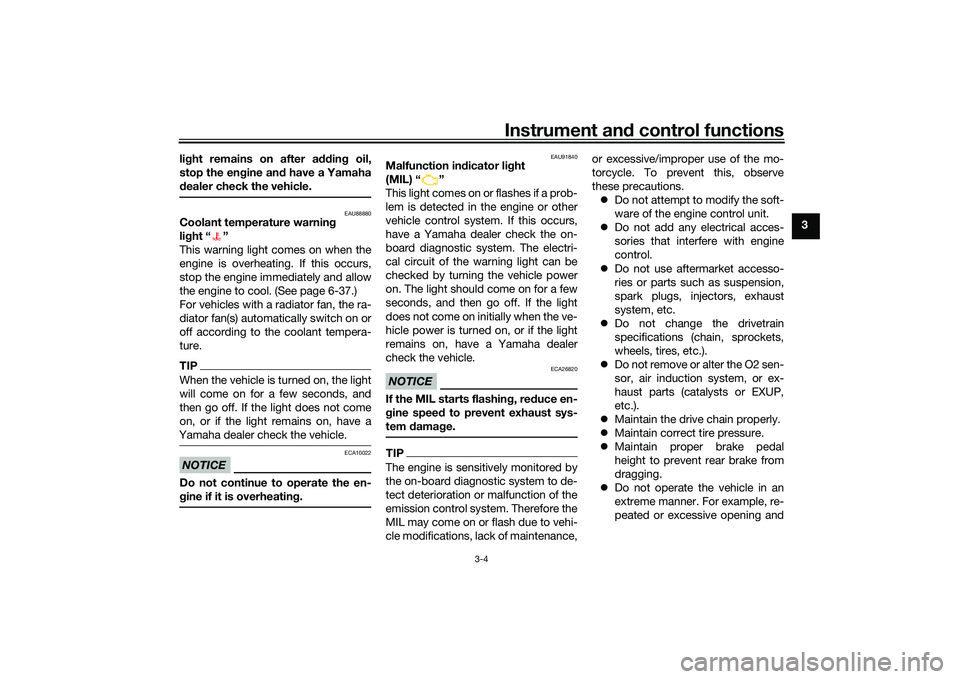
In dicator li ghts an d warnin g
li g hts
EAU88680
Turn si gnal in dicator li ghts “ ”
an d“”
Each indicator light will flash when its
corresponding turn signal lights are
flashing.
EAU91820
Neutral in dicator li ght “ ”
This indicator light comes on when the
transmission is in the neutral position.
EAU88690
Hi gh beam in dicator li ght “ ”
This indicator light comes on when the
high beam of the headlight is switched
on.
EAU91830
Oil pressure warnin g li ght “ ”
This warning light comes on if the en-
gine oil pressure is low.TIPWhen the vehicle is turned on, the light
should come on, go off briefly, and
then remain on until the engine is start-
ed. Otherwise, have a Yamaha dealer
check the vehicle.NOTICE
ECA21211
If the warnin g li ght comes on when
the en gine is runnin g, stop the en-
g ine an d check the oil level. If the oil
level is low, a dd sufficient oil of the
recommen ded type. If the warnin g
1. Push.
2. Turn.12
1. Left turn signal indicator light
Page 19 of 100

Instrument and control functions
3-4
3
lig
ht remains on after addin g oil,
stop the en gine an d have a Yamaha
d ealer check the vehicle.
EAU88880
Coolant temperature warnin g
lig ht “ ”
This warning light comes on when the
engine is overheating. If this occurs,
stop the engine immediately and allow
the engine to cool. (See page 6-37.)
For vehicles with a radiator fan, the ra-
diator fan(s) automatically switch on or
off according to the coolant tempera-
ture.TIPWhen the vehicle is turned on, the light
will come on for a few seconds, and
then go off. If the light does not come
on, or if the light remains on, have a
Yamaha dealer check the vehicle.NOTICE
ECA10022
Do not continue to operate the en-
g ine if it is overheatin g.
EAU91840
Malfunction in dicator li ght
(MIL) “ ”
This light comes on or flashes if a prob-
lem is detected in the engine or other
vehicle control system. If this occurs,
have a Yamaha dealer check the on-
board diagnostic system. The electri-
cal circuit of the warning light can be
checked by turning the vehicle power
on. The light should come on for a few
seconds, and then go off. If the light
does not come on initially when the ve-
hicle power is turned on, or if the light
remains on, have a Yamaha dealer
check the vehicle.NOTICE
ECA26820
If the MIL starts flashin g, re duce en-
g ine spee d to prevent exhaust sys-
tem damag e.TIPThe engine is sensitively monitored by
the on-board diagnostic system to de-
tect deterioration or malfunction of the
emission control system. Therefore the
MIL may come on or flash due to vehi-
cle modifications, lack of maintenance, or excessive/improper use of the mo-
torcycle. To prevent this, observe
these precautions.
Do not attempt to modify the soft-
ware of the engine control unit.
Do not add any electrical acces-
sories that interfere with engine
control.
Do not use aftermarket accesso-
ries or parts such as suspension,
spark plugs, injectors, exhaust
system, etc.
Do not change the drivetrain
specifications (chain, sprockets,
wheels, tires, etc.).
Do not remove or alter the O2 sen-
sor, air induction system, or ex-
haust parts (catalysts or EXUP,
etc.).
Maintain the drive chain properly.
Maintain correct tire pressure.
Maintain proper brake pedal
height to prevent rear brake from
dragging.
Do not operate the vehicle in an
extreme manner. For example, re-
peated or excessive opening and
UBEBE0E0.book Page 4 Monday, July 5, 2021 2:26 PM
Page 20 of 100

Instrument and control functions
3-5
3 closing of the throttle, racing,
burnouts, wheelies, extended
half-clutch use, etc.
EAU93230
ABS warnin
g li ght “ ”
This warning light comes on when the
vehicle is first turned on, and goes off
after starting riding. If the warning light
comes on while riding, the anti-lock
brake system may not work correctly.
WARNING
EWA21120
If the ABS warnin g lig ht does not
turn off after reachin g 5 km/h ( 3
mi/h), or if the warnin g li ght comes
on while rid ing:
Use extra caution to avoi d pos-
si ble wheel lock d uring emer-
g ency brakin g.
Have a Yamaha dealer check
the vehicle as soon as possi ble.
EAU92970
Shift timin g in dicator li ght
This indicator light can be set to come
on and go off at select engine speeds.
(See page 3-10.)
TIPWhen the vehicle is turned on, the light
should flash and then go off. If the light
does not flash, or if the light remains
on, have a Yamaha dealer check the
vehicle.
EAU92710
Immo bilizer system in dicator
li g ht “ ”
When the main switch is turned off and
30 seconds have passed, the indicator
light will flash steadily to indicate the
immobilizer system is enabled. After 24
hours have passed, the indicator light
will stop flashing, however the immobi-
lizer system is still enabled.TIPWhen the vehicle is turned on, this light
should come on for a few seconds and
then go off. If the light does not come
on, or if the light remains on, have a
Yamaha dealer check the vehicle.
Transpon der interference
If the immobilizer system indicator light
flashes in the pattern, slowly 5 times
then quickly 2 times, this could be
caused by transponder interference. If
this occurs, try the following. 1. Make sure there are no other im- mobilizer keys close to the main
switch.
2. Use the code re-registering key to start the engine.
3. If the engine starts, turn it off, and try starting the engine with the
standard keys.
4. If one or both of the standard keys do not start the engine, take the
vehicle and all 3 keys to a Yamaha
dealer to have the standard keys
re-registered.
UBEBE0E0.book Page 5 Monday, July 5, 2021 2:26 PM
Page 21 of 100

Instrument and control functions
3-6
3
EAU92981
Multi-function meter unit
The multi-function meter unit is also
equipped with a display brightness and
shift timing indicator light settings
mode.
WARNING
EWA12423
Be sure to stop the vehicle before
makin g any settin g chan ges to the
multi-function meter unit. Chan gin g
settin gs while ri din g can distract the
operator an d increase the risk of an
acci dent.
EAU92991
TIPThe multi-function meter is controlled
more information.
EAU93001
Switchin g the display units
The display units can be switched be-
tween kilometers and miles. To switch
the display units, set the multi-funtion
display to the odometer or a tripmeter,
and then hold the “SEL” switch until
the display units change.
EAU86831
Speed ometer
The speedometer shows the vehicle’s
traveling speed.
EAU87170
Tachometer
The tachometer allows the rider to
monitor the engine speed and keep it
within the ideal power range.NOTICE
ECA10032
Do not operate the en gine in the ta-
chometer red zone.
Re d zone: 10000 r/min an d a bove
1. Transmission gear display
2. Speedometer
3. Tachometer
4. Fuel meter
5. Clock
6. Multi-function display
7. Quick shifter indicator “QS” (if equipped)
1. “SEL/RES” switch
1
2
3
45
6
7
1 1 1
1. Tachometer
2. Tachometer red zone
1
2
UBEBE0E0.book Page 6 Monday, July 5, 2021 2:26 PM
Page 25 of 100

Instrument and control functions
3-10
3
“AVE_ _._ MPG”: the average dis-
tance that can be traveled on
1.0 Imp.gal of fuel.
TIPTo reset the display, change the
display to the average fuel con-
sumption display, and hold the
“RES” switch until it resets.
After resetting, “- -.-” is shown un-
til the vehicle has traveled some
distance.
EAU93210
Coolant temperature display
This display shows the coolant tem-
perature from 40 °C to 116 °C in 1 °C
increments. If the message “HI” flashes, stop the
vehicle, then stop the engine, and let it
cool. (See page 6-37.)
TIP
When the coolant temperature is
below 40 °C, “Lo” will be dis-
played.
The coolant temperature varies
with changes in the weather and
engine load.
EAU93222
Air temperature display
This display shows the air temperature
from –9 °C to 50 °C in 1 °C increments.
The temperature displayed may vary
from the actual ambient temperature.
TIPWhen the temperature is below …9 °C,
EAU93241
Display bri ghtness an d shift timin g
in dicator li ght settin gs mo de
The following settings can be adjusted
in order: Display brightness
Shift timing indicator light ON /
FLASH / OFF
Shift timing indicator light ON
r/min
Shift timing indicator light OFF
r/min
Shift timing indicator light bright-
ness
To access the settings mode1. Turn the vehicle off.
2. Hold the “SEL” switch, turn the vehicle on and continue holding
the “SEL” switch until the display
changes to the display brightness
control mode.
3. Use the “RES” switch to change the setting values.
1. Coolant temperature display
1
1. Air temperature display
1
UBEBE0E0.book Page 10 Monday, July 5, 2021 2:26 PM
Page 27 of 100

Instrument and control functions
3-12
3
Shift timing indicator light bright-
ness
The shift timing indicator light will
come on and stay on until the setting is
confirmed. The brightness level of the
light will change as the level is adjust-
ed.
Use the “RES” switch to select the de-
sired brightness level and push the
“SEL” to confirm it.
EAU1234R
Handlebar switchesLeft
Right
EAU12352
Pass switch “ ”
Press this switch to flash the headlight.TIPWhen the dimmer switch is set
to “ ”, the passing switch has no ef-
fect.
EAU12402
Dimmer switch “ / ”
Set this switch to “ ” for the high
beam and to “ ” for the low beam.
1. Pass switch “ ”
2. “SEL/RES” switch
3. Dimmer switch “ / ”
4. Turn signal switch “ / ”
5. Horn switch “ ”
1 1 1
2
4
5 3 2
4
5 3
1. Engine stop switch
Page 28 of 100

Instrument and control functions
3-13
3
EAU12461
Turn signal switch “ / ”
To signal a right-hand turn, push this
switch to “ ”. To signal a left-hand
turn, push this switch to “ ”. When
released, the switch returns to the cen-
ter position. To cancel the turn signal
lights, push the switch in after it has re-
turned to the center position.
EAU12501
Horn switch “ ”
Press this switch to sound the horn.
EAU12664
Engine stop switch “ / ”
Set this switch to “ ” (run) before
starting the engine. Set this switch
to “ ” (stop) to stop the engine in case
of an emergency, such as in the event
of an overturn or if the throttle is stuck.
EAU12713
Start switch “ ”
Push this switch to crank the engine
with the starter. See page 5-2 for start-
ing instructions prior to starting the en-
gine.
EAU88273
Hazard switch “OFF/ ”
Use this switch to turn on the hazard
lights (simultaneous flashing of all turn
signal lights). The hazard lights are
used in case of an emergency or to
warn other drivers when your vehicle is
stopped where it might be a traffic haz-
ard.
The hazard lights can be turned on or
off only when the main switch is in the
“ON” position. You can turn the main
switch to the “OFF” or “LOCK” posi-
tion, and the hazard lights will continue
to flash. To turn off the hazard lights,
turn the main switch to the “ON” posi-
tion and operate the hazard switch
again.NOTICE
ECA10062
Do not use the hazard lights for an
extended length of time with the en-
gine not running, otherwise the bat-
tery may discharge.
EAU88941
“SEL/RES” switch
This switch is used to make setting and
display changes in the multi-function
meter unit. See page 3-6 for more in-
formation.
To use the “SEL” switch, move the
“SEL/RES” switch in direction (a). To
use the “RES” switch, move the
“SEL/RES” switch in direction (b).1. “SEL/RES” switch
1 1 1
(a) (a)
(b) (b)
(a)
(b)
UBEBE0E0.book Page 13 Monday, July 5, 2021 2:26 PM
Page 32 of 100

Instrument and control functions
3-17
3
EAU13222
FuelMake sure there is sufficient gasoline in
the tank.
WARNING
EWA10882
Gasoline and gasoline vapors are
extremely flammable. To avoid fires
and explosions and to reduce the
risk of injury when refueling, follow
these instructions.1. Before refueling, turn off the en-gine and be sure that no one is sit-
ting on the vehicle. Never refuel
while smoking, or while in the vi-
cinity of sparks, open flames, or
other sources of ignition such as
the pilot lights of water heaters
and clothes dryers.
2. Do not overfill the fuel tank. When refueling, be sure to insert the
pump nozzle into the fuel tank filler
hole. Stop filling when the fuel
reaches the bottom of the filler
tube. Because fuel expands when
it heats up, heat from the engine or
the sun can cause fuel to spill out
of the fuel tank. 3. Wipe up any spilled fuel immedi-
ately. NOTICE: Immediately
wipe off spilled fuel with a clean,
dry, soft cloth, since fuel may
deteriorate painted surfaces or
plastic parts.
[ECA10072]
4. Be sure to securely close the fuel tank cap.
WARNING
EWA15152
Gasoline is poisonous and can
cause injury or death. Handle gaso-
line with care. Never siphon gasoline
by mouth. If you should swallow
some gasoline or inhale a lot of gas-
oline vapor, or get some gasoline in
your eyes, see your doctor immedi- ately. If gasoline spills on your skin,
wash with soap and water. If gaso-
line spills on your clothing, change
your clothes.
EAU86072
Your Yamaha engine was designed to
use unleaded gasoline with a research
octane number of 90 or higher. If en-
gine knocking or pinging occurs, use a
gasoline of a different brand or higher
octane rating.
1. Fuel tank filler tube
2. Maximum fuel level
2
1
Recommended fuel:
Unleaded gasoline (E10 acceptable)
Octane number (RON): 90
Fuel tank capacity: 13 L (3.4 US gal, 2.9 Imp.gal)
Fuel tank reserve:
2.5 L (0.66 US gal, 0.55 Imp.gal)
UBEBE0E0.book Page 17 Monday, July 5, 2021 2:26 PM
Page 37 of 100

Instrument and control functions
3-22
3
EAU76345
Adjusting the front fork
WARNING
EWA14671
Always adjust the spring preload on
both fork legs equally, otherwise
poor handling and loss of stability
may result.Each front fork leg is equipped with a
spring preload adjusting bolt, the right
front fork leg is equipped with a re-
bound damping force adjusting screw
and the left front fork leg with a com-
pression damping force adjusting
screw.NOTICE
ECA10102
To avoid damaging the mechanism,
do not attempt to turn beyond the
maximum or minimum settings.Spring preload
Turn the adjusting bolt in direction (a)
to increase the spring preload.
Turn the adjusting bolt in direction (b)
to decrease the spring preload.The spring preload setting is deter-
mined by measuring distance A,
shown in the illustration. The shorter
distance A is, the higher the spring pre-
load; the longer distance A is, the lower
the spring preload.
Rebound damping force
The rebound damping force is adjust-
ed on the right fork leg only.
Turn the adjusting screw in direction (a)
to increase the rebound damping
force.
Turn the adjusting screw in direction (b)
to decrease the rebound damping
force.
To set the rebound damping force, turn
the adjuster in direction (a) until it
stops, and then count the clicks in di-
rection (b).
TIPBe sure to perform this adjustment on
the right fork leg.
1. Spring preload adjusting bolt
1. Distance A
(a) (a)
(b) (b)
(a) (b) 1 1
1
Spring preload setting:
Minimum (soft):
Distance A = 19.0 mm (0.75 in)
Standard:
Distance A = 14.0 mm (0.55 in)
Maximum (hard): Distance A = 4.0 mm (0.16 in)
UBEBE0E0.book Page 22 Monday, July 5, 2021 2:26 PM
Page 38 of 100

Instrument and control functions
3-23
3
TIPWhen turning the damping force
adjuster in direction (a), the 0 click
position and the 1 click position
may be the same.
When turning the damping force
adjuster in direction (b), it may
click beyond the stated specifica- tions, however such adjustments
are ineffective and may damage
the suspension.
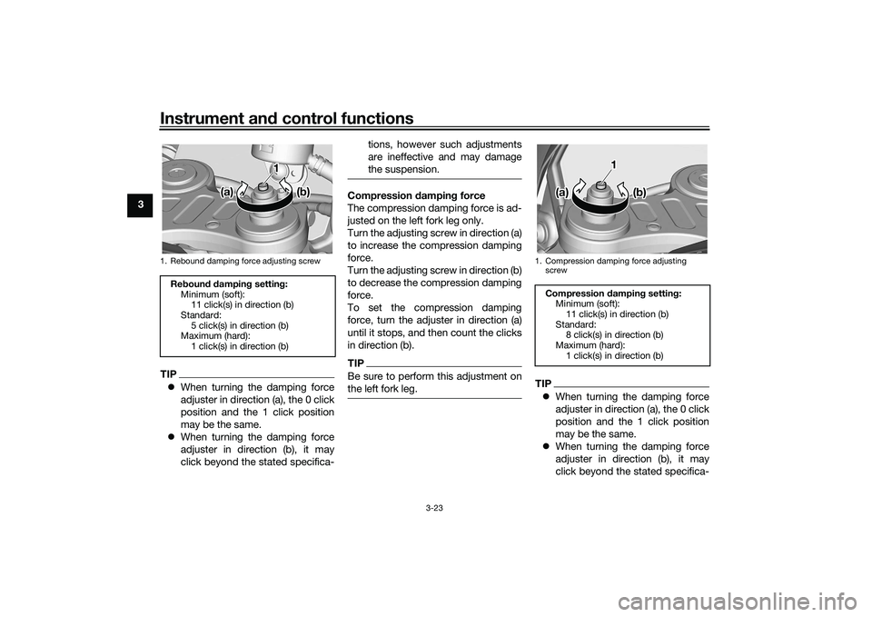
Compression damping force
The compression damping force is ad-
justed on the left fork leg only.
Turn the adjusting screw in direction (a)
to increase the compression damping
force.
Turn the adjusting screw in direction (b)
to decrease the compression damping
force.
To set the compression damping
force, turn the adjuster in direction (a)
until it stops, and then count the clicks
in direction (b).TIPBe sure to perform this adjustment on
the left fork leg.
TIP
When turning the damping force
adjuster in direction (a), the 0 click
position and the 1 click position
may be the same.
When turning the damping force
adjuster in direction (b), it may
click beyond the stated specifica-
1. Rebound damping force adjusting screwRebound damping setting:
Minimum (soft):11 click(s) in direction (b)
Standard: 5 click(s) in direction (b)
Maximum (hard):
1 click(s) in direction (b)
(a) (a) (b) (b)
(a) (b)
1 1
1. Compression damping force adjusting
screwCompression damping setting:Minimum (soft):11 click(s) in direction (b)
Standard: 8 click(s) in direction (b)
Maximum (hard):
1 click(s) in direction (b)
1 1 1
(a) (a) (b) (b)
(a) (b)
UBEBE0E0.book Page 23 Monday, July 5, 2021 2:26 PM