fuel filter YAMAHA YZF600 2000 Owners Manual
[x] Cancel search | Manufacturer: YAMAHA, Model Year: 2000, Model line: YZF600, Model: YAMAHA YZF600 2000Pages: 109, PDF Size: 5.01 MB
Page 52 of 109
PERIODIC MAINTENANCE AND MINOR REPAIR
6-2
6
EAU00473
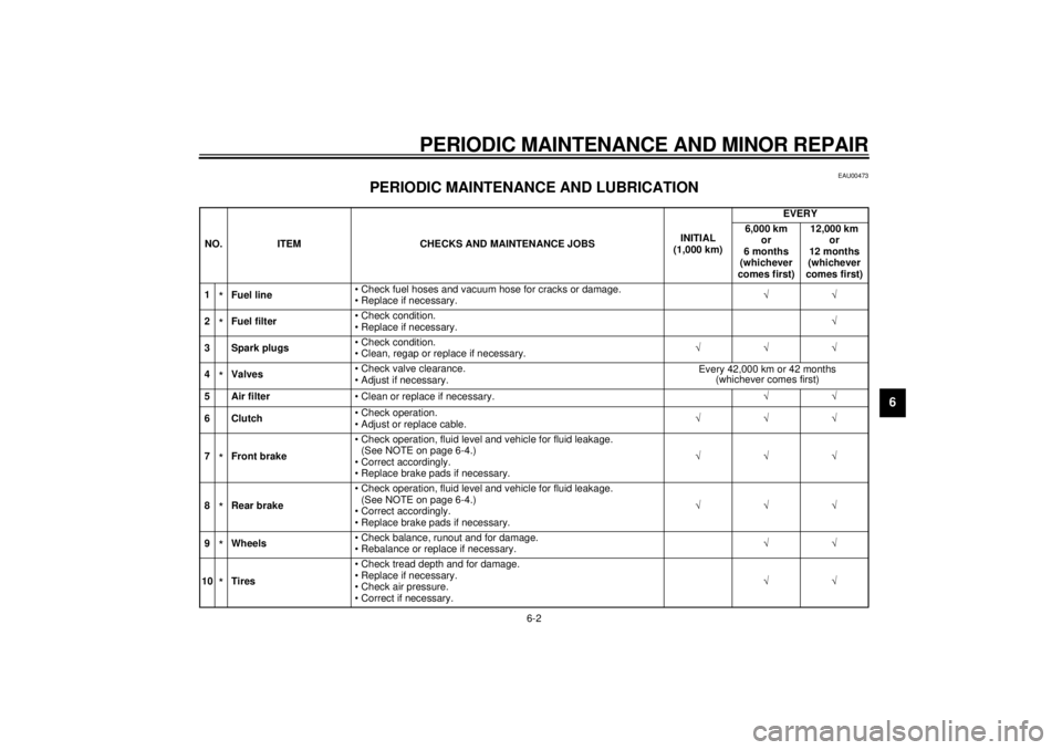
PERIODIC MAINTENANCE AND LUBRICATION
CP-01ENO. ITEM CHECKS AND MAINTENANCE JOBSINITIAL
(1,000 km)EVERY
6,000 km
or
6 months
(whichever
comes first)12,000 km
or
12 months
(whichever
comes first)
1
*Fuel line• Check fuel hoses and vacuum hose for cracks or damage.
• Replace if necessary.ÖÖ
2*Fuel filter• Check condition.
• Replace if necessary.Ö
3 Spark plugs• Check condition.
• Clean, regap or replace if necessary.ÖÖÖ
4*Valves• Check valve clearance.
• Adjust if necessary.Every 42,000 km or 42 months
(whichever comes first)
5 Air filter
• Clean or replace if necessary.ÖÖ
6Clutch• Check operation.
• Adjust or replace cable.ÖÖÖ
7*Front brake• Check operation, fluid level and vehicle for fluid leakage.
(See NOTE on page 6-4.)
• Correct accordingly.
• Replace brake pads if necessary.ÖÖÖ
8*Rear brake• Check operation, fluid level and vehicle for fluid leakage.
(See NOTE on page 6-4.)
• Correct accordingly.
• Replace brake pads if necessary.ÖÖÖ
9*Wheels• Check balance, runout and for damage.
• Rebalance or replace if necessary.ÖÖ
10*Tires• Check tread depth and for damage.
• Replace if necessary.
• Check air pressure.
• Correct if necessary.ÖÖ
E_4tv_Periodic.fm Page 2 Wednesday, September 1, 1999 11:12 AM
Page 65 of 109
PERIODIC MAINTENANCE AND MINOR REPAIR
6-15
6
NOTE:@ If you find any leaks, ask a Yamaha
dealer to inspect. @18. Install the right air intake duct, then
install and tighten the screw
clamps.
19. Install the fuel tank and fuel tank
bolts.
20. Install the coolant reservoir and
bolts.
21. Fill the coolant reservoir with the
recommended coolant to the
specified level.
22. Install cowlings A and B.
23. Install cowling C.
24. Install the seat.
EAU01475
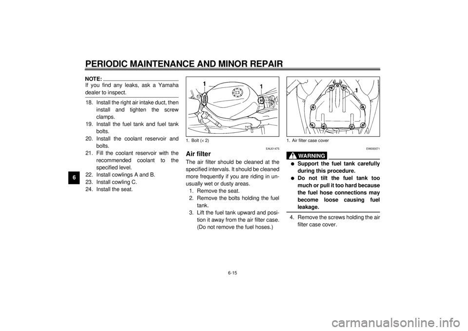
Air filterThe air filter should be cleaned at the
specified intervals. It should be cleaned
more frequently if you are riding in un-
usually wet or dusty areas.
1. Remove the seat.
2. Remove the bolts holding the fuel
tank.
3. Lift the fuel tank upward and posi-
tion it away from the air filter case.
(Do not remove the fuel hoses.)
EW000071
WA R N I N G
@ l
Support the fuel tank carefully
during this procedure.
l
Do not tilt the fuel tank too
much or pull it too hard because
the fuel hose connections may
become loose causing fuel
leakage.
@4. Remove the screws holding the air
filter case cover.
1. Bolt (´ 2)
1. Air filter case cover
E_4tv_Periodic.fm Page 15 Wednesday, September 1, 1999 11:12 AM
Page 66 of 109
PERIODIC MAINTENANCE AND MINOR REPAIR
6-16
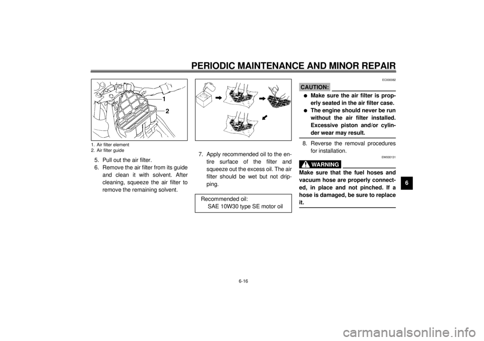
6 5. Pull out the air filter.
6. Remove the air filter from its guide
and clean it with solvent. After
cleaning, squeeze the air filter to
remove the remaining solvent.7. Apply recommended oil to the en-
tire surface of the filter and
squeeze out the excess oil. The air
filter should be wet but not drip-
ping.
EC000082
CAUTION:@ l
Make sure the air filter is prop-
erly seated in the air filter case.
l
The engine should never be run
without the air filter installed.
Excessive piston and/or cylin-
der wear may result.
@8. Reverse the removal procedures
for installation.
EW000131
WA R N I N G
@ Make sure that the fuel hoses and
vacuum hose are properly connect-
ed, in place and not pinched. If a
hose is damaged, be sure to replace
it. @
1. Air filter element
2. Air filter guide
Recommended oil:
SAE 10W30 type SE motor oil
E_4tv_Periodic.fm Page 16 Wednesday, September 1, 1999 11:12 AM
Page 99 of 109
8-1
8
EAU01038
8-SPECIFICATIONSSpecifications01E
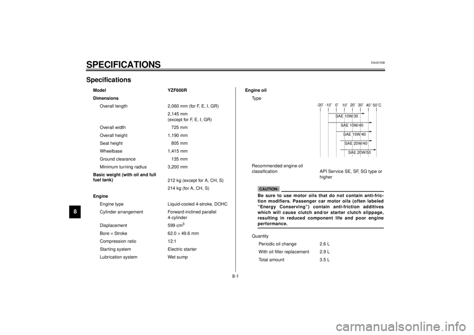
Model YZF600R
Dimensions
Overall length 2,060 mm (for F, E, I, GR)
2,145 mm
(except for F, E, I, GR)
Overall width 725 mm
Overall height 1,190 mm
Seat height 805 mm
Wheelbase 1,415 mm
Ground clearance 135 mm
Minimum turning radius 3,200 mm
Basic weight (with oil and full
fuel tank)
212 kg (except for A, CH, S)
214 kg (for A, CH, S)
Engine
Engine type Liquid-cooled 4-stroke, DOHC
Cylinder arrangement Forward-inclined parallel
4-cylinder
Displacement 599 cm
3
Bore ´ Stroke 62.0 ´ 49.6 mm
Compression ratio 12:1
Starting system Electric starter
Lubrication system Wet sumpEngine oil
Ty p e
Recommended engine oil
classification API Service SE, SF, SG type or
higher
Quantity
Periodic oil change 2.6 L
With oil filter replacement 2.9 L
Total amount 3.5 L
-20˚ -10˚ 0˚
10˚20˚ 30˚
40˚50˚C
SAE 10W/30
SAE 15W/40SAE 20W/40SAE 20W/50
SAE 10W/40
CAUTION:Be sure to use motor oils that do not contain anti-fric-
tion modifiers. Passenger car motor oils (often labeled
“Energy Conserving”) contain anti-friction additives
which will cause clutch and/or starter clutch slippage,
resulting in reduced component life and poor engine
performance.
E_4tv_Spec.fm Page 1 Wednesday, September 1, 1999 11:14 AM
Page 100 of 109
SPECIFICATIONS
8-2
8
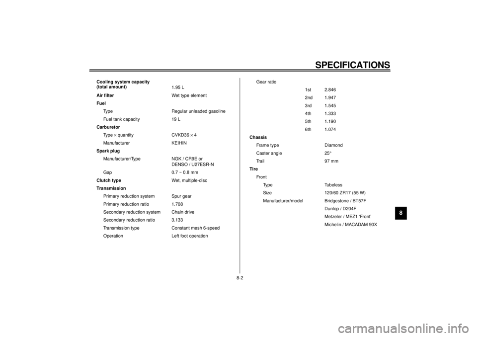
Cooling system capacity
(total amount)
1.95 L
Air filter
Wet type element
Fuel
Type Regular unleaded gasoline
Fuel tank capacity 19 L
Carburetor
Ty p e ´ quantity CVKD36 ´ 4
Manufacturer KEIHIN
Spark plug
Manufacturer/Type NGK / CR9E or
DENSO / U27ESR-N
Gap 0.7 ~ 0.8 mm
Clutch type
Wet, multiple-disc
Transmission
Primary reduction system Spur gear
Primary reduction ratio 1.708
Secondary reduction system Chain drive
Secondary reduction ratio 3.133
Transmission type Constant mesh 6-speed
Operation Left foot operationGear ratio
1st 2.846
2nd 1.947
3rd 1.545
4th 1.333
5th 1.190
6th 1.074
Chassis
Frame type Diamond
Caster angle 25°
Tr a i l 9 7 m m
Tire
Fro nt
Ty p e Tu b e l e s s
Size 120/60 ZR17 (55 W)
Manufacturer/model Bridgestone / BT57F
Dunlop / D204F
Metzeler / MEZ1 ‘Front’
Michelin / MACADAM 90X
E_4tv_Spec.fm Page 2 Wednesday, September 1, 1999 11:14 AM
Page 107 of 109
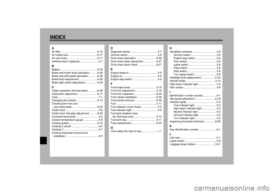
10-INDEXAAir filter ..................................................6-15
Air intake duct ........................................6-17
Air vent hose .......................................... 6-17
Antitheft alarm (optional) .......................... 3-7BBattery ................................................... 6-32
Brake and clutch lever lubrication........... 6-29
Brake and shift pedal lubrication ............ 6-29
Brake fluid replacement ......................... 6-26
Brake light switch adjustment ................. 6-24CCable inspection and lubrication ............ 6-28
Carburetor adjustment ...........................6-17
Care.........................................................7-1
Changing the coolant ............................. 6-13
Checking the front and
rear brake pads ................................... 6-25
Clutch lever .............................................. 3-9
Clutch lever free play adjustment ........... 6-23
Controls/Instruments ................................2-3
Coolant temperature gauge ..................... 3-8
Cooling system ...................................... 6-12
Cowling A and B ......................................6-5
Cowling C ................................................6-7
Cowling and panel removal and
installation .............................................6-5
DDiagnosis device ..................................... 3-7
Dimmer switch ......................................... 3-8
Drive chain lubrication ........................... 6-28
Drive chain slack adjustment ................. 6-27
Drive chain slack check ......................... 6-27EEngine break-in ....................................... 5-5
Engine oil ................................................ 6-9
Engine stop switch................................... 3-9FFront brake lever ................................... 3-10
Front fork adjustment............................. 3-16
Front fork inspection .............................. 6-30
Front wheel installation .......................... 6-36
Front wheel removal .............................. 6-35
Fuel ....................................................... 3-11
Fuel indicator circuit check....................... 3-5
Fuel indicator light ................................... 3-2
Fuel tank breather hose
(for Germany only) .............................. 3-13
Fuel tank cap ......................................... 3-11
Fuse replacement.................................. 6-33GGive safety the right of way ..................... 1-1
HHandlebar switches ..................................3-8
Dimmer switch ....................................3-8
Engine stop switch..............................3-9
Horn switch.........................................3-8
Lights switch .......................................3-9
Pass switch ........................................3-8
Start switch .........................................3-9
Turn signal switch ...............................3-8
Headlight bulb replacement....................6-33
Helmet holder.........................................3-15
High beam indicator light ..........................3-3
Horn switch ..............................................3-8IIdentification number records ...................9-1
Idle speed adjustment ............................6-18
Indicator lights ..........................................3-2
Fuel indicator light...............................3-2
High beam indicator light ....................3-3
Neutral indicator light ..........................3-2
Oil level indicator light .........................3-2
Turn indicator light ..............................3-3
Inspecting the brake fluid level ...............6-25KKey identification number .........................9-1LLeft view...................................................2-1
Lights switch ............................................3-9
Luggage strap holders ...........................3-21
E_4tvIX.fm Page 1 Wednesday, September 1, 1999 11:15 AM