ECU YAMAHA YZF600 2001 Owners Manual
[x] Cancel search | Manufacturer: YAMAHA, Model Year: 2001, Model line: YZF600, Model: YAMAHA YZF600 2001Pages: 114, PDF Size: 12.39 MB
Page 27 of 114
INSTRUMENT AND CONTROL FUNCTIONS
3-12
3
EAU01688
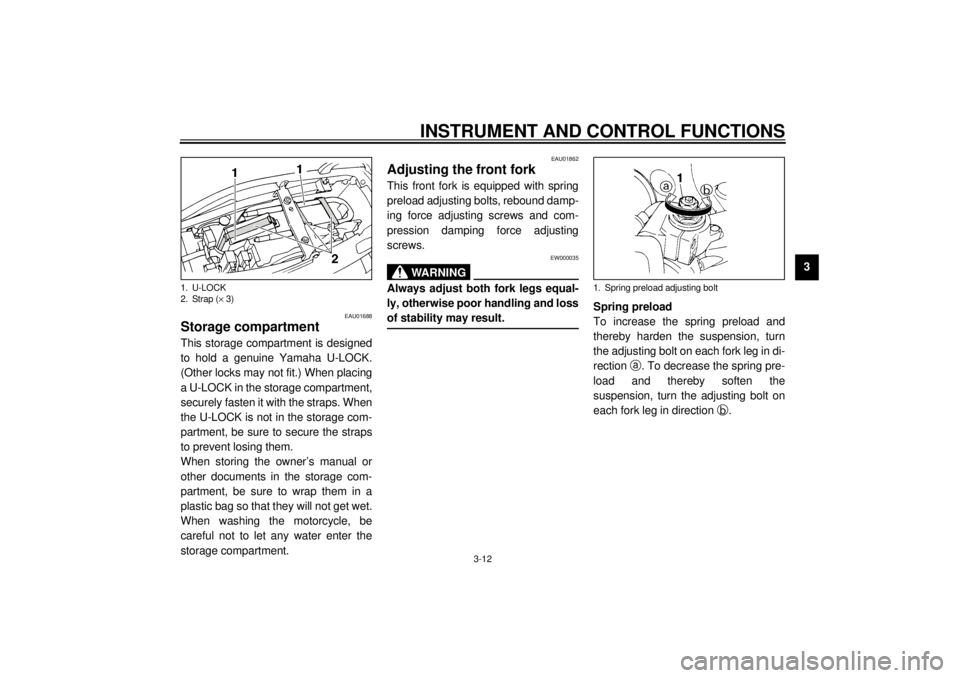
Storage compartment This storage compartment is designed
to hold a genuine Yamaha U-LOCK.
(Other locks may not fit.) When placing
a U-LOCK in the storage compartment,
securely fasten it with the straps. When
the U-LOCK is not in the storage com-
partment, be sure to secure the straps
to prevent losing them.
When storing the owner’s manual or
other documents in the storage com-
partment, be sure to wrap them in a
plastic bag so that they will not get wet.
When washing the motorcycle, be
careful not to let any water enter the
storage compartment.
EAU01862
Adjusting the front fork This front fork is equipped with spring
preload adjusting bolts, rebound damp-
ing force adjusting screws and com-
pression damping force adjusting
screws.
EW000035
WARNING
_ Always adjust both fork legs equal-
ly, otherwise poor handling and loss
of stability may result. _
Spring preload
To increase the spring preload and
thereby harden the suspension, turn
the adjusting bolt on each fork leg in di-
rection
a. To decrease the spring pre-
load and thereby soften the
suspension, turn the adjusting bolt on
each fork leg in direction
b.
1. U-LOCK
2. Strap (´ 3)
1. Spring preload adjusting bolt
E_4tv.book Page 12 Wednesday, October 4, 2000 2:15 PM
Page 71 of 114
PERIODIC MAINTENANCE AND MINOR REPAIR
6-22
6
l
Securely pack the heaviest
items close to the center of the
motorcycle and distribute the
weight evenly on both sides.
l
Adjust the suspension and tire
air pressure with regard to the
load.
l
Check the tire condition and air
pressure before each ride.
_
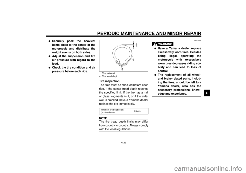
Tire inspection
The tires must be checked before each
ride. If the center tread depth reaches
the specified limit, if the tire has a nail
or glass fragments in it, or if the side-
wall is cracked, have a Yamaha dealer
replace the tire immediately.CE-08ENOTE:_ The tire tread depth limits may differ
from country to country. Always comply
with the local regulations. _
EW000079
WARNING
_ l
Have a Yamaha dealer replace
excessively worn tires. Besides
being illegal, operating the
motorcycle with excessively
worn tires decreases riding sta-
bility and can lead to loss of
control.
l
The replacement of all wheel-
and brake-related parts, includ-
ing the tires, should be left to a
Yamaha dealer, who has the
necessary professional knowl-
edge and experience.
_
1. Tire sidewall
a. Tire tread depthMinimum tire tread depth
(front and rear)1.6 mm
E_4tv.book Page 22 Wednesday, October 4, 2000 2:15 PM
Page 72 of 114
PERIODIC MAINTENANCE AND MINOR REPAIR
6-23
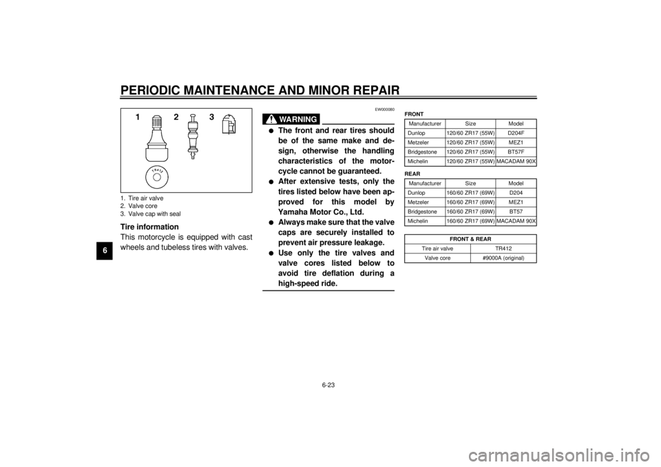
6Tire information
This motorcycle is equipped with cast
wheels and tubeless tires with valves.
EW000080
WARNING
_ l
The front and rear tires should
be of the same make and de-
sign, otherwise the handling
characteristics of the motor-
cycle cannot be guaranteed.
l
After extensive tests, only the
tires listed below have been ap-
proved for this model by
Yamaha Motor Co., Ltd.
l
Always make sure that the valve
caps are securely installed to
prevent air pressure leakage.
l
Use only the tire valves and
valve cores listed below to
avoid tire deflation during a
high-speed ride.
_
CE-10E
CE-14E
1. Tire air valve
2. Valve core
3. Valve cap with seal
FRONT
Manufacturer Size Model
Dunlop 120/60 ZR17 (55W) D204F
Metzeler 120/60 ZR17 (55W) MEZ1
Bridgestone 120/60 ZR17 (55W) BT57F
Michelin 120/60 ZR17 (55W) MACADAM 90X
REAR
Manufacturer Size Model
Dunlop 160/60 ZR17 (69W) D204
Metzeler 160/60 ZR17 (69W) MEZ1
Bridgestone 160/60 ZR17 (69W) BT57
Michelin 160/60 ZR17 (69W) MACADAM 90X
FRONT & REAR
Tire air valve TR412
Valve core #9000A (original)
E_4tv.book Page 23 Wednesday, October 4, 2000 2:15 PM
Page 82 of 114
PERIODIC MAINTENANCE AND MINOR REPAIR
6-33
6
EAU00790
Lubricating the rear
suspension The pivoting points of the rear suspen-
sion must be lubricated at the intervals
specified in the periodic maintenance
and lubrication chart.
EAU02939
Checking the front fork The condition and operation of the front
fork must be checked as follows at the
intervals specified in the periodic main-
tenance and lubrication chart.
To check the condition
EW000115
WARNING
_ Securely support the motorcycle so
that there is no danger of it falling
over. _Check the inner tubes for scratches,
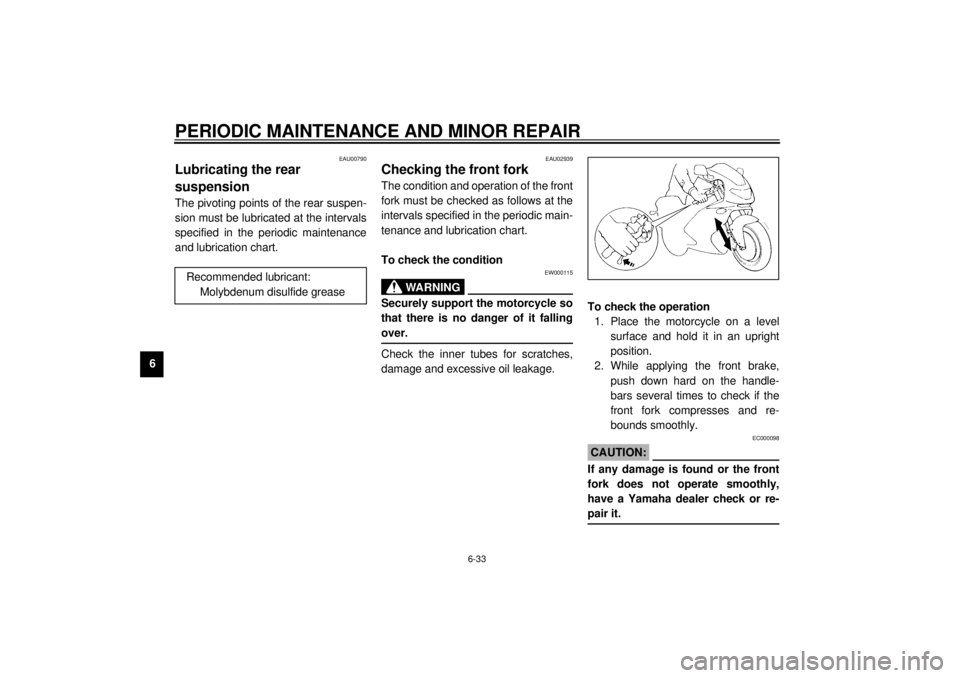
damage and excessive oil leakage.To check the operation
1. Place the motorcycle on a level
surface and hold it in an upright
position.
2. While applying the front brake,
push down hard on the handle-
bars several times to check if the
front fork compresses and re-
bounds smoothly.
EC000098
CAUTION:_ If any damage is found or the front
fork does not operate smoothly,
have a Yamaha dealer check or re-
pair it. _
Recommended lubricant:
Molybdenum disulfide grease
E_4tv.book Page 33 Wednesday, October 4, 2000 2:15 PM
Page 83 of 114
PERIODIC MAINTENANCE AND MINOR REPAIR
6-34
6
EAU00794
Checking the steering Worn or loose steering bearings may
cause danger. Therefore, the operation
of the steering must be checked as fol-
lows at the intervals specified in the pe-
riodic maintenance and lubrication
chart.
1. Place a stand under the engine to
raise the front wheel off the
ground.
EW000115
WARNING
_ Securely support the motorcycle so
that there is no danger of it falling
over. _
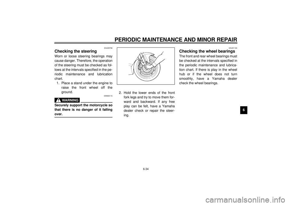
2. Hold the lower ends of the front
fork legs and try to move them for-
ward and backward. If any free
play can be felt, have a Yamaha
dealer check or repair the steer-
ing.
EAU01144
Checking the wheel bearings The front and rear wheel bearings must
be checked at the intervals specified in
the periodic maintenance and lubrica-
tion chart. If there is play in the wheel
hub or if the wheel does not turn
smoothly, have a Yamaha dealer
check the wheel bearings.
E_4tv.book Page 34 Wednesday, October 4, 2000 2:15 PM
Page 87 of 114
PERIODIC MAINTENANCE AND MINOR REPAIR
6-38
6
EW000119
WARNING
_ Headlight bulbs get very hot. There-
fore, keep flammable products away
from a lit headlight bulb, and do not
touch the bulb until it has cooled
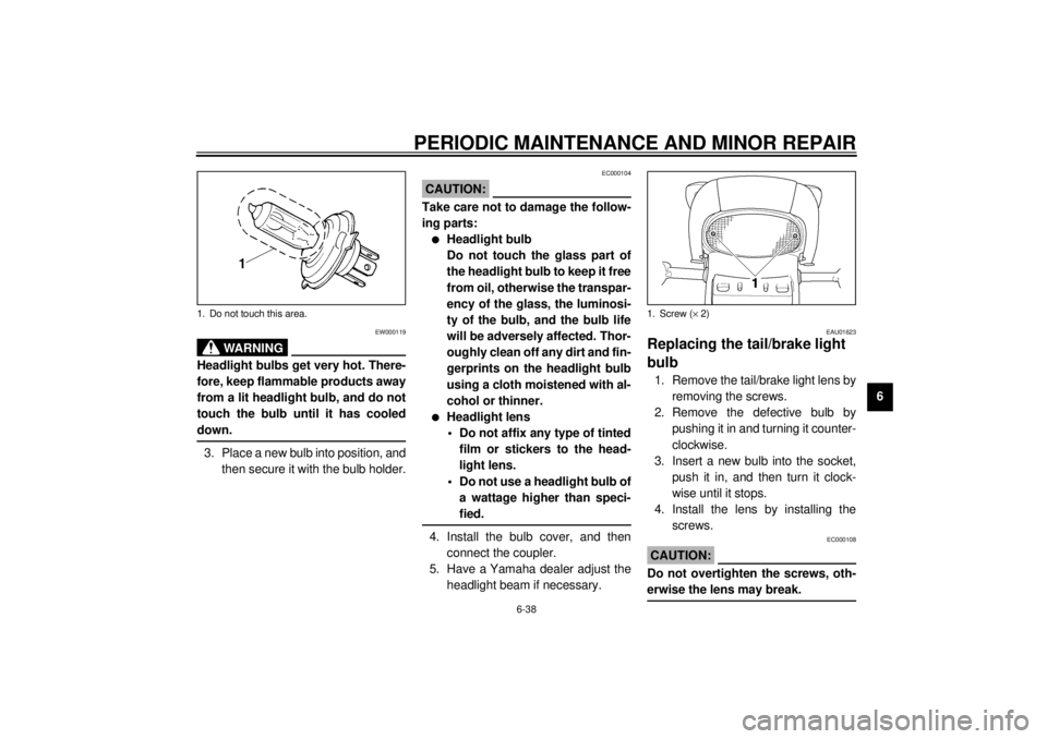
down. _3. Place a new bulb into position, and
then secure it with the bulb holder.
EC000104
CAUTION:_ Take care not to damage the follow-
ing parts:l
Headlight bulb
Do not touch the glass part of
the headlight bulb to keep it free
from oil, otherwise the transpar-
ency of the glass, the luminosi-
ty of the bulb, and the bulb life
will be adversely affected. Thor-
oughly clean off any dirt and fin-
gerprints on the headlight bulb
using a cloth moistened with al-
cohol or thinner.
l
Headlight lens
• Do not affix any type of tinted
film or stickers to the head-
light lens.
• Do not use a headlight bulb of
a wattage higher than speci-
fied.
_4. Install the bulb cover, and then
connect the coupler.
5. Have a Yamaha dealer adjust the
headlight beam if necessary.
EAU01623
Replacing the tail/brake light
bulb 1. Remove the tail/brake light lens by
removing the screws.
2. Remove the defective bulb by
pushing it in and turning it counter-
clockwise.
3. Insert a new bulb into the socket,
push it in, and then turn it clock-
wise until it stops.
4. Install the lens by installing the
screws.
EC000108
CAUTION:_ Do not overtighten the screws, oth-
erwise the lens may break. _
1. Do not touch this area.
1. Screw (´ 2)
E_4tv.book Page 38 Wednesday, October 4, 2000 2:15 PM
Page 89 of 114
PERIODIC MAINTENANCE AND MINOR REPAIR
6-40
6
EAU03582
Front wheel To remove the front wheel
EW000122
WARNING
_ l
It is advisable to have a Yamaha
dealer service the wheel.
l
Securely support the motor-
cycle so that there is no danger
of it falling over.
_1. Disconnect the speedometer ca-
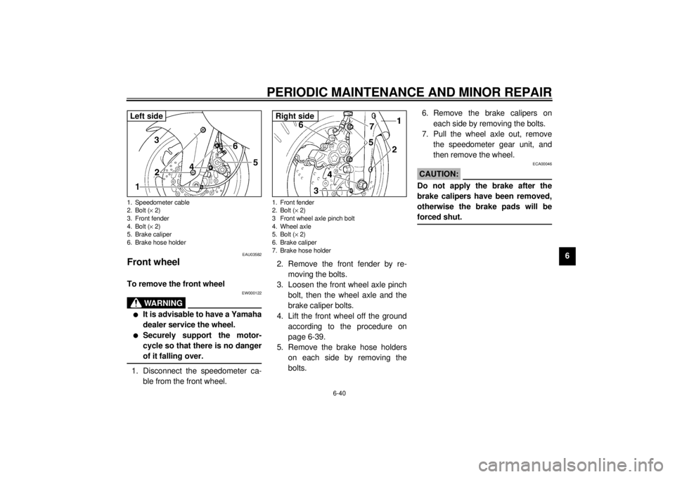
ble from the front wheel.2. Remove the front fender by re-
moving the bolts.
3. Loosen the front wheel axle pinch
bolt, then the wheel axle and the
brake caliper bolts.
4. Lift the front wheel off the ground
according to the procedure on
page 6-39.
5. Remove the brake hose holders
on each side by removing the
bolts.6. Remove the brake calipers on
each side by removing the bolts.
7. Pull the wheel axle out, remove
the speedometer gear unit, and
then remove the wheel.
ECA00046
CAUTION:_ Do not apply the brake after the
brake calipers have been removed,
otherwise the brake pads will be
forced shut. _
1. Speedometer cable
2. Bolt (´ 2)
3. Front fender
4. Bolt (´ 2)
5. Brake caliper
6. Brake hose holderLeft side
1. Front fender
2. Bolt (´ 2)
3 Front wheel axle pinch bolt
4. Wheel axle
5. Bolt (´ 2)
6. Brake caliper
7. Brake hose holderRight side
E_4tv.book Page 40 Wednesday, October 4, 2000 2:15 PM
Page 90 of 114
PERIODIC MAINTENANCE AND MINOR REPAIR
6-41
6
EAU03583
To install the front wheel
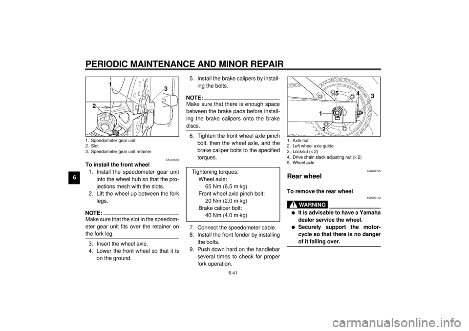
1. Install the speedometer gear unit
into the wheel hub so that the pro-
jections mesh with the slots.
2. Lift the wheel up between the fork
legs.NOTE:_ Make sure that the slot in the speedom-
eter gear unit fits over the retainer on
the fork leg. _3. Insert the wheel axle.
4. Lower the front wheel so that it is
on the ground.5. Install the brake calipers by install-
ing the bolts.
NOTE:_ Make sure that there is enough space
between the brake pads before install-
ing the brake calipers onto the brake
discs. _6. Tighten the front wheel axle pinch
bolt, then the wheel axle, and the
brake caliper bolts to the specified
torques.
7. Connect the speedometer cable.
8. Install the front fender by installing
the bolts.
9. Push down hard on the handlebar
several times to check for proper
fork operation.
EAU03795
Rear wheel To remove the rear wheel
EW000122
WARNING
_ l
It is advisable to have a Yamaha
dealer service the wheel.
l
Securely support the motor-
cycle so that there is no danger
of it falling over.
_
1. Speedometer gear unit
2. Slot
3. Speedometer gear unit retainer
Tightening torques:
Wheel axle:
65 Nm (6.5 m·kg)
Front wheel axle pinch bolt:
20 Nm (2.0 m·kg)
Brake caliper bolt:
40 Nm (4.0 m·kg)
1. Axle nut
2. Left wheel axle guide
3. Locknut (´ 2)
4. Drive chain slack adjusting nut (´ 2)
5. Wheel axle
E_4tv.book Page 41 Wednesday, October 4, 2000 2:15 PM