steering wheel Abarth 124 Spider 2020 Owner handbook (in English)
[x] Cancel search | Manufacturer: ABARTH, Model Year: 2020, Model line: 124 Spider, Model: Abarth 124 Spider 2020Pages: 224, PDF Size: 3.9 MB
Page 5 of 224
HOW TO USE THIS MANUAL
ESSENTIAL INFORMATION
Each time directions are given in the instructions (left/right or forward/backwards), these must be intended as referred to the
point of view of an occupant in the driver's seat. Special cases not complying with this rule will be properly specified in the text.
The figures in the Owner Handbook are provided by way of example only: this might imply that some details of the image do
not correspond to the actual arrangement of your vehicle. In addition, the Handbook has been conceived considering vehicles
with steering wheel on the left side; it is therefore possible that on vehicles with steering wheel on the right side, the position of
some controls or elements is not exactly mirror-like with respect to the figure.
To identify the chapter with the information needed you can consult the index at the end of this Owner Handbook.
Chapters can be rapidly identified by graphic tabs, at the side of each odd page. A key showing the order of the chapter and
the corresponding tab symbols appears on another page.
SYMBOLS
While reading this Owner Handbook you will find a series ofWARNINGSto prevent procedures that could damage your
vehicle.
There are alsoPRECAUTIONSthat must be carefully followed to prevent incorrect use of the components of the vehicle,
which could cause accidents or injuries.
Therefore, allWARNINGSandPRECAUTIONSmust always be carefully followed.
WARNINGSandPRECAUTIONSare recalled in the text with the following symbols:
personal
safety
vehicle
safety
environmentalprotection
Page 9 of 224
GETTING TO KNOW YOUR VEHICLE
In-depth knowledge of your new vehicle
starts here.
The handbook that you are reading
simply and directly explains how it is
made and how it works.
That’s why we advise you to read it
seated comfortably on board, so that
you can see immediately what is
described here for yourself.DASHBOARD................8
KEYS.....................9
IGNITION SWITCH............11
ADVANCED KEYLESS ENTRY
SYSTEM..................14
VEHICLE SECURITY ALARM.....14
DOORS...................16
SEATS....................19
HEAD RESTRAINTS...........21
STEERING WHEEL............21
MIRRORS..................22
EXTERIOR LIGHTS............24
WINDSCREEN WIPERS / WASHER .28
CLIMATE CONTROL SYSTEM.....31
POWER WINDOWS...........36
INTERNAL EQUIPMENT........38
BOOT LID..................38
BONNET..................41
CONVERTIBLE TOP (SOFT TOP) . . .42
7
Page 13 of 224
IGNITION SWITCH
PUSH BUTTON START
POSITIONS
The system operates only when the key
is within operational range.
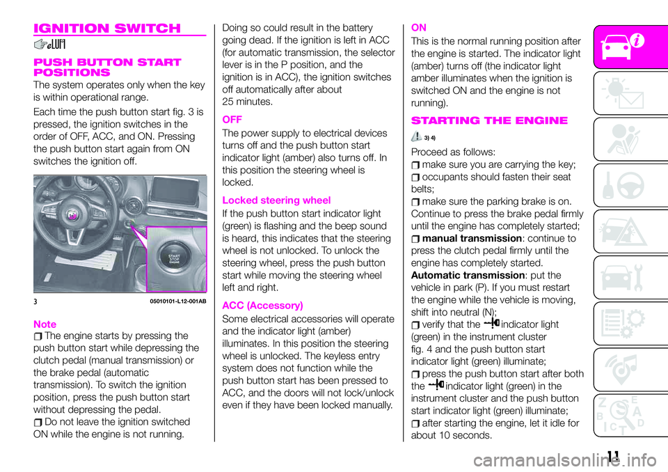
Each time the push button start fig. 3 is
pressed, the ignition switches in the
order of OFF, ACC, and ON. Pressing
the push button start again from ON
switches the ignition off.
NoteThe engine starts by pressing the
push button start while depressing the
clutch pedal (manual transmission) or
the brake pedal (automatic
transmission). To switch the ignition
position, press the push button start
without depressing the pedal.
Do not leave the ignition switched
ON while the engine is not running.Doing so could result in the battery
going dead. If the ignition is left in ACC
(for automatic transmission, the selector
lever is in the P position, and the
ignition is in ACC), the ignition switches
off automatically after about
25 minutes.
OFF
The power supply to electrical devices
turns off and the push button start
indicator light (amber) also turns off. In
this position the steering wheel is
locked.
Locked steering wheel
If the push button start indicator light
(green) is flashing and the beep sound
is heard, this indicates that the steering
wheel is not unlocked. To unlock the
steering wheel, press the push button
start while moving the steering wheel
left and right.
ACC (Accessory)
Some electrical accessories will operate
and the indicator light (amber)
illuminates. In this position the steering
wheel is unlocked. The keyless entry
system does not function while the
push button start has been pressed to
ACC, and the doors will not lock/unlock
even if they have been locked manually.
ON
This is the normal running position after
the engine is started. The indicator light
(amber) turns off (the indicator light
amber illuminates when the ignition is
switched ON and the engine is not
running).
STARTING THE ENGINE
3) 4)
Proceed as follows:
make sure you are carrying the key;
occupants should fasten their seat
belts;
make sure the parking brake is on.
Continue to press the brake pedal firmly
until the engine has completely started;
manual transmission: continue to
press the clutch pedal firmly until the
engine has completely started.
Automatic transmission: put the
vehicle in park (P). If you must restart
the engine while the vehicle is moving,
shift into neutral (N);
verify that theindicator light
(green) in the instrument cluster
fig. 4 and the push button start
indicator light (green) illuminate;
press the push button start after both
the
indicator light (green) in the
instrument cluster and the push button
start indicator light (green) illuminate;
after starting the engine, let it idle for
about 10 seconds.
305010101-L12-001AB
11
Page 23 of 224
30)Do not use the seat warmer with
anything having high moisture retention
ability such as a blanket or cushion on the
seat. The seat may be heated excessively
and cause a low-temperature burn.
31)Do not place objects on the seat or on
the backrest that may isolate the heat,
such as a cover or a pillow. It may cause
the seat heating device to overheat. Sitting
on an overheated seat may cause severe
burns due to the increase in temperature of
the seat surface.
32)Do not place heavy objects with sharp
projections on the seat, or insert needles or
pins into it. This could cause the seat to
become excessively heated and result in
injury from a minor burn.
33)Do not use the seat warmer even when
taking a short nap in the vehicle. The seat
may be heated excessively and cause a
low-temperature burn.
IMPORTANT
7)The fabric upholstery for the seats has
been designed to withstand long-term wear
deriving from normal use of the vehicle.
Nevertheless, some precautions are
required. Avoid prolonged and/or excessive
rubbing involving clothing accessories such
as metal buckles, bosses, Velcro strips and
the like, which, by applying a high pressure
on the fabric in a limited area, could cause
it to break, thereby damaging the
upholstery.
HEAD RESTRAINTS
34)
Non-Adjustable Head Restraints
Your vehicle is equipped with non
adjustable head restraints on the
driver's and passenger's seatbacks.
The non adjustable head restraints
consist of a trimmed foam covering
over the upper structure of the
seatbacks and are intended to help
protect you and the passenger from
neck injury.
Adjust the seatbacks to their upright,
on-road positions so that the head
restraint is positioned as close as
possible to the back of your head.
WARNING
34)Make sure the seatbacks are properly
adjusted to their upright, on-road positions
before the vehicle is driven. Driving with the
seatbacks not adjusted properly is
dangerous. With no support behind your
head, your neck could be seriously injured
in a collision.
STEERING WHEEL
STEERING WHEEL
ADJUSTMENT
35) 36) 37)
To change the angle of the steering
wheel:
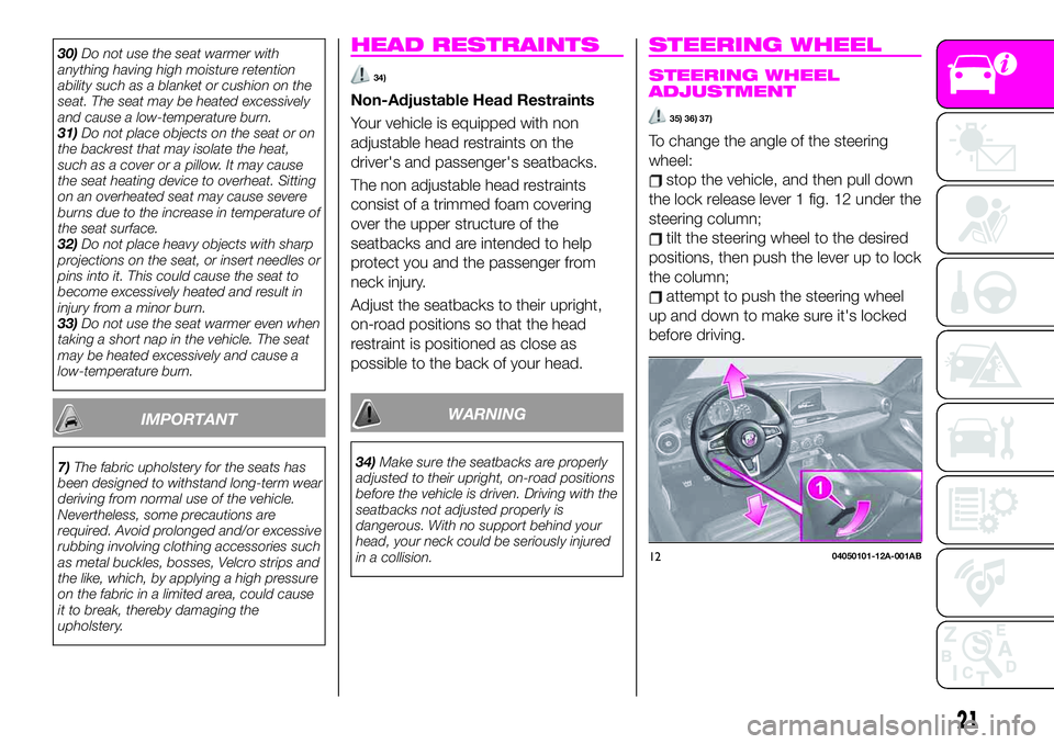
stop the vehicle, and then pull down
the lock release lever 1 fig. 12 under the
steering column;
tilt the steering wheel to the desired
positions, then push the lever up to lock
the column;
attempt to push the steering wheel
up and down to make sure it's locked
before driving.
1204050101-12A-001AB
21
Page 24 of 224
WARNING
35)Any adjustment of the steering wheel
position must be carried out only with the
vehicle stationary and the engine turned
off. Adjusting the steering wheel while the
vehicle is moving is dangerous. Moving it
can very easily cause the driver to abruptly
turn to the left or right. This can lead to loss
of control or an accident.
36)It is absolutely forbidden to carry out
any aftermarket operation involving steering
system or steering column modifications
(e.g. installation of antitheft device) that
could adversely affect performance and
safety, invalidate the warranty and also
result in the vehicle not meeting
type-approval requirements.
37)Before exiting the vehicle, ALWAYS
engage the parking brake, steer the
wheels, engage the first gear if uphill and
the reverse if downhill. If the vehicle is
parked on a steep slope, chock the wheels
with wedges or stones. When leaving the
vehicle, always lock all the doors by
pressing the button on the key.
MIRRORS
OUTSIDE MIRRORS
38)
Driver's side wide angle mirror
(where provided)
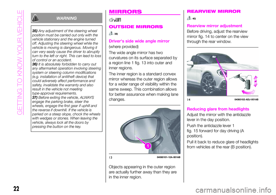
The wide angle mirror has two
curvatures on its surface separated by
a region line 1 fig. 13 into outer and
inner regions.
The inner region is a standard convex
mirror whereas the outer region allows
for a wider range of visibility within the
same sweep. This combination allows
for better assurance when making lane
changes.
Objects appearing in the outer region
are actually further away than they are
in the inner region.
REARVIEW MIRROR
40)
Rearview mirror adjustment
Before driving, adjust the rearview
mirror fig. 14 to center on the view
through the rear window.
Reducing glare from headlights
Adjust the mirror with the antidazzle
lever in the day position.
Push the antidazzle lever 1
fig. 15 forward for day driving (A
position).
Pull it back to reduce glare of headlights
from vehicles at the rear (B position).
1304060101-12A-001AB
1404060102-ADJ-001AB
22
GETTING TO KNOW YOUR VEHICLE
Page 29 of 224
instrument cluster illuminates while the
rear fog light is on.
Deactivation
To turn the rear fog light off, do any of
the following:
rotate the fog light switch 2 to the
position again (the fog light switch
automatically returns to the
position);
rotate the fog light switch 2 to the
OFF position;
turn the headlight switch 1 to the
OFF position.
The rear fog light indicator light in the
instrument cluster goes off when the
rear fog light is turned off.
TURN SIGNALS
The ignition must be switched ON to
use the turn and lane-change signals.
Direction indicators
Move the signal lever down (for a left
turn) or up (for a right turn) to the stop
position. The signal will self-cancel after
the turn is completed.
If the indicator light continues to flash
after a turn, manually return the lever to
its original position.
The turn signal indicators (green)
in the instrument cluster flash
according to the operation of the turn
signal lever to show which signal is
working.
NOTE If an indicator light stays on
without flashing or if it flashes
abnormally, one of the turn signal bulbs
may be burned out.
LANE CHANGE SIGNALS
Move the lever halfway toward the
direction of the lane change (until the
indicator flashes) and hold it there. It will
return to the off position when released.
Three-flash turn signal
After releasing the turn signal lever, the
turn signal indicator flashes three times.
The operation can be cancelled by
moving the lever in the direction
opposite to which it was operated.
Adaptive Front Lighting
System (AFS)
(where provided)
The adaptive front lighting system (AFS)
automatically adjusts the headlight
beams to the left or right in conjunction
with the operation of the steering wheel
after the headlights have been turned
on.
A system malfunction or operation
conditions are indicated by a warning.
Refer to “Warning lights on instrument
panel” paragraph in “Knowing the
instrument panel” chapter.
NOTE
Headlights are equipped which do
not blind drivers approaching in theopposite direction no matter what side
of the road you must drive your vehicle
(left-hand or right-hand traffic).
Therefore, it is not necessary to adjust
the optical axis of the headlights when
switching temporarily to driving on the
opposite side of the road (left-hand or
right-hand traffic).
The Adaptive Front Lighting System
(AFS) function can be switched to
operable/ inoperable using the
personalisation function. Refer to
“Personalisation features” paragraph in
“Knowing the instrument panel”
chapter.
LEAVING HOME LIGHT
SYSTEM
The leaving home light system turns on
the lights when the transmitter unlock
button is pressed while away from the
vehicle.
Activation
When the ignition switch and the
headlight switch are as indicated below,
the headlights will illuminate when the
transmitter unlock button is pressed
and the vehicle receives the transmitter
signal.
The headlights turn off after a certain
period of time has elapsed
(30 seconds).
Ignition switch:off.
27
Page 66 of 224
Warning light What it means What to do
POWER STEERING MALFUNCTION
INDICATOR LIGHT
The light illuminates if the electric power
steering has a malfunction. If the light
illuminates, stop the vehicle in a safe place
and do not operate the steering wheel. There
is no problem if the light turns off after a while.
Contact an Abarth Dealership if the light
illuminates continuously.
NOTE If the indicator light illuminates, the
power steering will not operate normally. If this
happens, the steering wheel can still be
operated, however, the operation may feel
heavy compared to normal, or the steering
wheel could vibrate when turning.
NOTE Repeatedly jerking the steering wheel
left and right while the vehicle is stopped or
moving extremely slowly will cause the power
steering system to go into protective mode
which will make the steering feel heavy, but
this does not indicate a problem. If this occurs,
park the vehicle safely and wait several
minutes for the system to return to normal.Contact an Abarth Dealership if the light
illuminatescontinuously.
64
KNOWING THE INSTRUMENT PANEL
Page 69 of 224

Warning light What it means What to do
TCS / DSC SYSTEM INDICATOR LIGHT
The warning light turns on when the in case of
intervention of TCS/DSC systems. This means
that the vehicle is in critical stability and grip
conditions.
DSC OFF INDICATOR LIGHT
This indicator light stays on for a few seconds
when the ignition is switched ON. It also
illuminates when the DSC OFF switch is
pressed and TCS/DSC is switched off. Refer
to “DSC OFF switch” in “Active safety
systems” paragraph (“Safety” chapter).If the light remains illuminated and the
TCS/DSC is not switched off, take your
vehicle to an Abarth Dealership. The DSC may
have a malfunction.
REAR FOG LIGHT INDICATOR LIGHT
The warning light switches on when the rear
fog light is turned on.
ADJUSTABLE SPEED LIMITER MAIN
INDICATOR LIGHT (where provided)
The warning light switches on when the
MODE switch on steering wheel is pressed
and the adjustable speed limiter is activated
(see “Speed limiter” paragraph in “Starting and
driving” chapter).
WRENCH INDICATOR LIGHT
(where provided)
When the ignition is switched ON, the wrench
indicator light is illuminated and then turns off
after a few seconds.The wrench indicator light turns on when the
preset maintenance period arrives. Verify the
content and perform maintenance. Refer to
“Maintenance monitor” paragraph in this
chapter.
67
Page 102 of 224

SUPPLEMENTARY
RESTRAINT SYSTEM
SRS - AIR BAG
SUPPLEMENTAL
RESTRAINT SYSTEM
(SRS) PRECAUTIONS
116) 117) 118)
The front and side supplementary
restraint systems (SRS) include different
types of air bags.
IMPORTANT Please verify which kinds
of air bags are equipped on your
vehicle by locating the “SRS AIR BAG”
location indicators.
These indicators are visible in the area
where the air bags are installed.
The air bags are installed in the
following locations:
the steering wheel hub (driver air
bag);
the passenger dashboard (passenger
air bag);
the outer sides of the seat backs
(side air bags).The air bag supplementary restraint
systems are designed to provide
supplementary protection in certain
situations so seat belts are always
important in the following ways.
Without seat belt usage, the air bags
cannot provide adequate protection
during an accident. Seat belt usage is
necessary to:
keep the occupant from being
thrown into an inflating air bag;
reduce the possibility of injuries
during an accident that is not designed
for air bag inflation, such as roll-over or
rear impact;
reduce the possibility of injuries in
frontal, near frontal or side collisions
that are not severe enough to activate
the air bags;
reduce the possibility of being thrown
from your vehicle;
reduce the possibility of injuries to
lower body and legs during an accident
because the air bags provide no
protection to these parts of the body;
hold the driver in a position which
allows better control of the vehicle.A child who is too small to use a seat
belt must be properly secured using a
child-restraint system.
Carefully consider which child-restraint
system is necessary for your child and
follow the installation directions in this
Owner Handbook as well as the
child-restraint system manufacturer's
instructions.
100
SAFETY
Page 104 of 224

HOW THE SRS AIR BAGS
WORK
119) 120) 121) 122) 123) 124) 125) 126) 127) 128) 129) 130)
131)
Your vehicle is equipped with the
following types of SRS air bags. SRS air
bags are designed to work together
with the seat belts to help to reduce
injuries during an accident. The SRS air
bags are designed to provide further
protection for passengers in addition to
the seat belt functions. Be sure to wear
seat belts properly.
Seat Belt Pretensioners
The seat belt pretensioners are
designed to deploy in moderate or
severe frontal, near frontal collisions. In
addition, during a side collision, the
pretensioner operates on the side in
which the collision occurs. The
pretensioners operate differently
depending on what types of air bags
are equipped. For more details on the
seat belt pretensioner operation, refer
to the “SRS Air Bag deployment
criteria” paragraph.
Driver Air Bag
The driver's air bag is mounted in the
steering wheel fig. 76.
When air bag crash sensors detect a
frontal impact of greater than moderate
force, the driver's air bag inflates quickly
helping to reduce injury mainly to the
driver's head or chest caused by
directly hitting the steering wheel. For
more details about air bag deployment,
refer to "SRS Air Bag deployment
criteria" in this chapter.
Passenger Air Bag(Single stage)
The passenger air bag is mounted in
the passenger dashboard fig. 77.
The inflation mechanism for the
passenger air bag is the same as the
driver's air bag. For more details about
air bag deployment, refer to "SRS Air
Bag deployment criteria" in this chapter.
In addition, the passenger air bag is
designed to only deploy when the
passenger occupant classification
sensor detects a passenger sitting on
the passenger's seat. For more details
about air bag deployment, refer to
"SRS Air Bag deployment criteria" in
this chapter.
7606010203-126-123AB
7706010204-126-123AB
102
SAFETY