lock Abarth 124 Spider 2021 Owner handbook (in English)
[x] Cancel search | Manufacturer: ABARTH, Model Year: 2021, Model line: 124 Spider, Model: Abarth 124 Spider 2021Pages: 224, PDF Size: 3.9 MB
Page 144 of 224
REPLACING EXTERIOR
LIGHT BULBS
Headlights (low beam)(versions with halogen bulb)
Proceed as follows:
if you are changing the right bulb,
start the engine, turn the steering wheel
all the way to the right, and turn off
engine. If you are changing the left bulb,
turn the steering wheel to the left;
make sure the headlight switch is off;
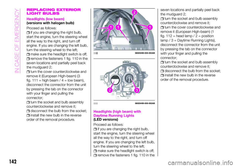
remove the fasteners 1 fig. 110 in the
seven locations and partially peel back
the mudguard 2;
turn the cover counterclockwise and
remove it (European High-beam) (3
fig. 111 = high beam/4=lowbeam),
disconnect the connector from the unit
by pressing the tab on the connector
with your finger and pulling the
connector;
turn the socket and bulb assembly
counterclockwise and remove it;
disconnect the bulb from the socket;
install the new bulb in the reverse
order of the removal procedure.Headlights (high beam) with
Daytime Running Lights
(LED versions)
Proceed as follows:
if you are changing the right bulb,
start the engine, turn the steering wheel
all the way to the right, and turn off
engine. If you are changing the left bulb,
turn the steering wheel to the left;
make sure the headlight switch is off;
remove the fasteners 1 fig. 110 in theseven locations and partially peel back
the mudguard 2;
turn the socket and bulb assembly
counterclockwise and remove it;
turn the cover counterclockwise and
remove it (European High-beam) (1
fig. 112 = head lamp/2=position
lamp / 3 = Daytime Running Lights),
disconnect the connector from the unit
by pressing the tab on the connector
with your finger and pulling the
connector;
turn the socket and bulb assembly
counterclockwise and remove it;
disconnect the bulb from the socket;
install the new bulb in the reverse
order of the removal procedure.
11008020499-000-003AB
11108020499-000-002AB
142
IN CASE OF EMERGENCY
Page 145 of 224
Front direction indicator lights
Proceed as follows:
if you are changing the right bulb,
start the engine, turn the steering wheel
all the way to the right, and turn off
engine. If you are changing the left bulb,
turn the steering wheel to the left.
make sure the ignition is switched
off, and the headlight switch is off;
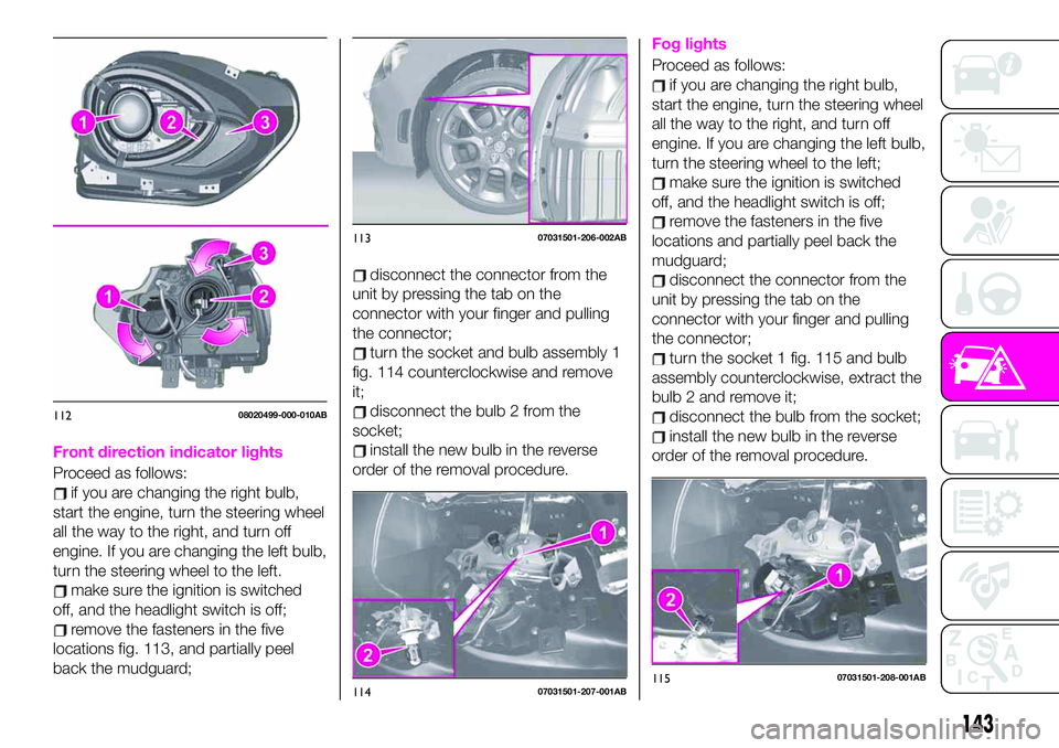
remove the fasteners in the five
locations fig. 113, and partially peel
back the mudguard;
disconnect the connector from the
unit by pressing the tab on the
connector with your finger and pulling
the connector;
turn the socket and bulb assembly 1
fig. 114 counterclockwise and remove
it;
disconnect the bulb 2 from the
socket;
install the new bulb in the reverse
order of the removal procedure.
Fog lights
Proceed as follows:
if you are changing the right bulb,
start the engine, turn the steering wheel
all the way to the right, and turn off
engine. If you are changing the left bulb,
turn the steering wheel to the left;
make sure the ignition is switched
off, and the headlight switch is off;
remove the fasteners in the five
locations and partially peel back the
mudguard;
disconnect the connector from the
unit by pressing the tab on the
connector with your finger and pulling
the connector;
turn the socket 1 fig. 115 and bulb
assembly counterclockwise, extract the
bulb 2 and remove it;
disconnect the bulb from the socket;
install the new bulb in the reverse
order of the removal procedure.
11208020499-000-010AB
11307031501-206-002AB
11407031501-207-001AB11507031501-208-001AB
143
Page 147 of 224
Position lights(LED versions)
Proceed as follows:
remove the fasteners in the seven
locations and partially peel back the
upper side of the mudguard;
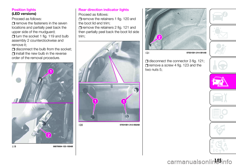
turn the socket 1 fig. 119 and bulb
assembly 2 counterclockwise and
remove it;
disconnect the bulb from the socket;
install the new bulb in the reverse
order of the removal procedure.
Rear direction indicator lights
Proceed as follows:
remove the retainers 1 fig. 120 and
the boot lid end trim;
remove the retainers 2 fig. 121 and
then partially peel back the boot lid side
trim;
disconnect the connector 3 fig. 121;
remove a screw 4 fig. 123 and the
two nuts 5;
11908070604-123-100AB
12007031501-212-002AB
12107031501-214-001AB
145
Page 148 of 224
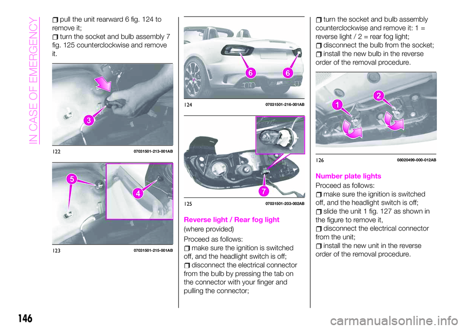
pull the unit rearward 6 fig. 124 to
remove it;
turn the socket and bulb assembly 7
fig. 125 counterclockwise and remove
it.
Reverse light / Rear fog light
(where provided)
Proceed as follows:
make sure the ignition is switched
off, and the headlight switch is off;
disconnect the electrical connector
from the bulb by pressing the tab on
the connector with your finger and
pulling the connector;
turn the socket and bulb assembly
counterclockwise and remove it: 1 =
reverse light/2=rearfoglight;
disconnect the bulb from the socket;
install the new bulb in the reverse
order of the removal procedure.
Number plate lights
Proceed as follows:
make sure the ignition is switched
off, and the headlight switch is off;
slide the unit 1 fig. 127 as shown in
the figure to remove it,
disconnect the electrical connector
from the unit;
install the new unit in the reverse
order of the removal procedure.
12207031501-213-001AB
12307031501-215-001AB
12407031501-216-001AB
12507031501-203-002AB
12608020499-000-012AB
146
IN CASE OF EMERGENCY
Page 150 of 224

pull the fuse straight out with the fuse
puller provided on the fuse block
located in the engine compartment
fig. 129;
inspect the fuse and replace it if it is
blown;
insert a new fuse of the same
amperage rating, and make sure it fits
tightly. If it does not fit tightly, contact an
Abarth Dealership. If you have no spare
fuses, borrow one of the same rating
from a circuit not essential to vehicle
operation, such as the AUDIO or
OUTLET circuit;
reinstall the cover and make sure that
it is securely installed.
IMPORTANT Always replace a fuse with
a genuine FCA fuse or equivalent of the
same rating. Otherwise you may
damage the electric system.
FUSES UNDER THE
BONNET
Make sure the ignition is switched off,
and other switches are off and remove
the fuse block cover. If the lock is
forcefully opened, the fuse block cover
may come in contact with the frame
when it is removed and become
scratched.
When removing the cover, remove it
slowly according to the following
procedure:
disengage the rear lock 1 fig. 130 by
pressing down on the front tab with
your fingers;
remove the front tab while slightly
lifting the front of the cover 2;
remove the cover while lifting it and
sliding it to the rear;
if any fuse but the MAIN fuse is
blown, replace it with a new one of the
same amperage rating;
reinstall the cover and make sure that
it is securely installed.
12907031601-122-001AB
13007031601-123-001AB
148
IN CASE OF EMERGENCY
Page 151 of 224

FUSE BLOCK (ENGINE COMPARTMENT)
13107031602-121-001
149
Page 152 of 224

DESCRIPTION FUSE RATING PROTECTED COMPONENT
F03 HORN2 7.5 A Horn
F06 — — —
F07 INTERIOR 15 A Overhead light
F09 AUDIO2 15 A Audio system
F10 METER1 10 A Instrument cluster
F11 SRS1 7.5 A Air bag
F12 — — —
F13 RADIO 7.5 A Audio system
F17 AUDIO1 25 A Audio system
F18 A/C MAG 7.5 A Air conditioner
F20 AT 15 A Transmission control system (where provided)
F21 D LOCK 25 A Power door locks
F22 H/L RH 20 A Headlight (RH)
F24 TAIL 20 A Taillights/Number plate lights/Position lights
F25 DRL 15 A Daylight Running Lights
F26 ROOM 25 A Overhead light
F27 FOG 15 A Fog lights
F28 H/CLEAN 20 A Headlight washer (where provided)
F29 STOP 10 A Stop lights/Rear fog light (where provided)
F30 HORN 15 A Horn
F31 H/L LH 20 A Headlight (LH)
F33 HAZARD 15 A Hazard warning flashers/Direction indicators lights
F36 WIPER 20 A Windscreen wipers
150
IN CASE OF EMERGENCY
Page 155 of 224
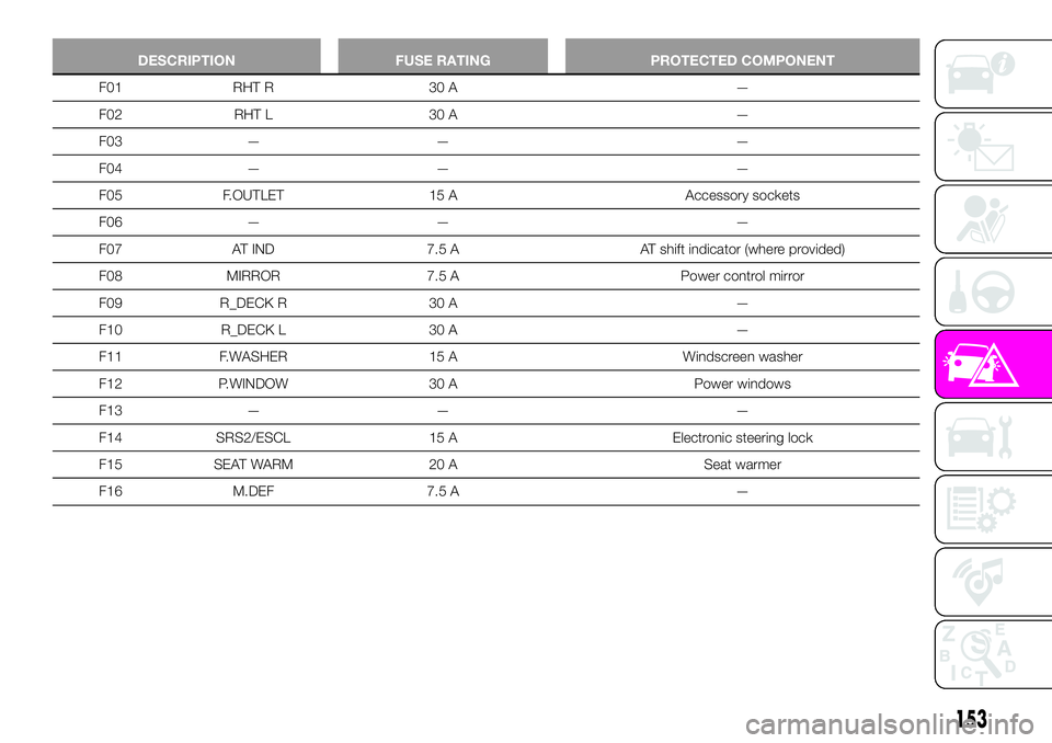
DESCRIPTION FUSE RATING PROTECTED COMPONENT
F01 RHT R 30 A —
F02 RHT L 30 A —
F03 — — —
F04 — — —
F05 F.OUTLET 15 A Accessory sockets
F06 — — —
F07 AT IND 7.5 A AT shift indicator (where provided)
F08 MIRROR 7.5 A Power control mirror
F09 R_DECK R 30 A —
F10 R_DECK L 30 A —
F11 F.WASHER 15 A Windscreen washer
F12 P.WINDOW 30 A Power windows
F13 — — —
F14 SRS2/ESCL 15 A Electronic steering lock
F15 SEAT WARM 20 A Seat warmer
F16 M.DEF 7.5 A —
153
Page 158 of 224

IMPORTANT If there is air remaining in
the tire when the valve core is removed,
the valve core could fly out. Remove
the valve core carefully.
turn the valve core 7 counter
clockwise with the valve core tool 8 and
remove the valve core fig. 137;
IMPORTANT Store the valve core in a
place where it will not get dirty.
insert the injection hose 9fig. 138 into the valve 10;
hold the bottom of the bottle upright
11 fig. 139, squeeze the bottle with
your hands, and inject the entire
amount of tire sealant into the tire;
pull out the injection hose from the
valve fig. 140;
reinsert the valve core 12 into the
valve 13 and turn it clockwise to install.
NOTE The tire sealant cannot be
reused. Purchase a new tire sealant kit
at an Abarth Dealership.
NOTE Do not throw away the empty
tire sealant bottle after use. Return the
empty tire sealant bottle to an Abarth
Dealership when replacing the tire. The
empty tire sealant bottle will need to be
used to extract and dispose of the used
sealant from the tire.
after that, install the injection hose to
the tab 14 fig. 141 of the bottle to
prevent leakage of any remaining
sealant;
adhere the speed restriction sticker
to an area where it can be viewed easily
by the driver;
pull out the air compressor hose and
the air compressor plug from the air
compressor 15 fig. 142;
install the air compressor hose 16 to
13608020202-03A-004AB
13708020202-03A-005AB
13808020202-03A-006AB
13908020202-03A-008AB
14008020202-03A-007AB
156
IN CASE OF EMERGENCY
Page 168 of 224
fluids. Please dispose of your waste
properly and with due regard to the
environment.
We recommend that you entrust the oil
and fluid changes of your vehicle to an
Abarth Dealership.
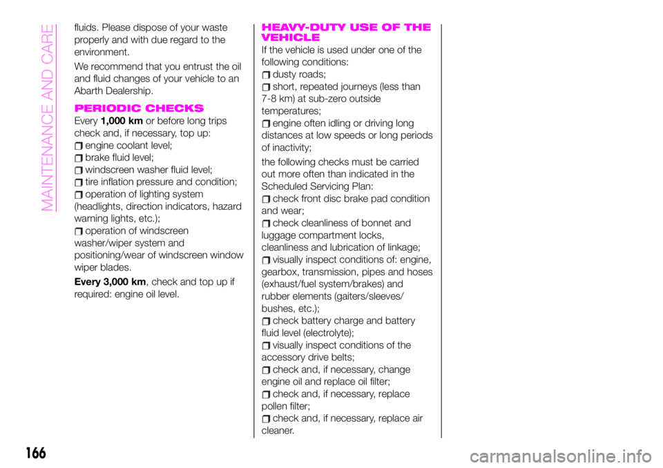
PERIODIC CHECKS
Every1,000 kmor before long trips
check and, if necessary, top up:
engine coolant level;
brake fluid level;
windscreen washer fluid level;
tire inflation pressure and condition;
operation of lighting system
(headlights, direction indicators, hazard
warning lights, etc.);
operation of windscreen
washer/wiper system and
positioning/wear of windscreen window
wiper blades.
Every 3,000 km, check and top up if
required: engine oil level.
HEAVY-DUTY USE OF THE
VEHICLE
If the vehicle is used under one of the
following conditions:
dusty roads;
short, repeated journeys (less than
7-8 km) at sub-zero outside
temperatures;
engine often idling or driving long
distances at low speeds or long periods
of inactivity;
the following checks must be carried
out more often than indicated in the
Scheduled Servicing Plan:
check front disc brake pad condition
and wear;
check cleanliness of bonnet and
luggage compartment locks,
cleanliness and lubrication of linkage;
visually inspect conditions of: engine,
gearbox, transmission, pipes and hoses
(exhaust/fuel system/brakes) and
rubber elements (gaiters/sleeves/
bushes, etc.);
check battery charge and battery
fluid level (electrolyte);
visually inspect conditions of the
accessory drive belts;
check and, if necessary, change
engine oil and replace oil filter;
check and, if necessary, replace
pollen filter;
check and, if necessary, replace air
cleaner.
166
MAINTENANCE AND CARE