headlight bulb Abarth 124 Spider 2021 Owner handbook (in English)
[x] Cancel search | Manufacturer: ABARTH, Model Year: 2021, Model line: 124 Spider, Model: Abarth 124 Spider 2021Pages: 224, PDF Size: 3.9 MB
Page 29 of 224
instrument cluster illuminates while the
rear fog light is on.
Deactivation
To turn the rear fog light off, do any of
the following:
rotate the fog light switch 2 to the
position again (the fog light switch
automatically returns to the
position);
rotate the fog light switch 2 to the
OFF position;
turn the headlight switch 1 to the
OFF position.
The rear fog light indicator light in the
instrument cluster goes off when the
rear fog light is turned off.
TURN SIGNALS
The ignition must be switched ON to
use the turn and lane-change signals.
Direction indicators
Move the signal lever down (for a left
turn) or up (for a right turn) to the stop
position. The signal will self-cancel after
the turn is completed.
If the indicator light continues to flash
after a turn, manually return the lever to
its original position.
The turn signal indicators (green)
in the instrument cluster flash
according to the operation of the turn
signal lever to show which signal is
working.
NOTE If an indicator light stays on
without flashing or if it flashes
abnormally, one of the turn signal bulbs
may be burned out.
LANE CHANGE SIGNALS
Move the lever halfway toward the
direction of the lane change (until the
indicator flashes) and hold it there. It will
return to the off position when released.
Three-flash turn signal
After releasing the turn signal lever, the
turn signal indicator flashes three times.
The operation can be cancelled by
moving the lever in the direction
opposite to which it was operated.
Adaptive Front Lighting
System (AFS)
(where provided)
The adaptive front lighting system (AFS)
automatically adjusts the headlight
beams to the left or right in conjunction
with the operation of the steering wheel
after the headlights have been turned
on.
A system malfunction or operation
conditions are indicated by a warning.
Refer to “Warning lights on instrument
panel” paragraph in “Knowing the
instrument panel” chapter.
NOTE
Headlights are equipped which do
not blind drivers approaching in theopposite direction no matter what side
of the road you must drive your vehicle
(left-hand or right-hand traffic).
Therefore, it is not necessary to adjust
the optical axis of the headlights when
switching temporarily to driving on the
opposite side of the road (left-hand or
right-hand traffic).
The Adaptive Front Lighting System
(AFS) function can be switched to
operable/ inoperable using the
personalisation function. Refer to
“Personalisation features” paragraph in
“Knowing the instrument panel”
chapter.
LEAVING HOME LIGHT
SYSTEM
The leaving home light system turns on
the lights when the transmitter unlock
button is pressed while away from the
vehicle.
Activation
When the ignition switch and the
headlight switch are as indicated below,
the headlights will illuminate when the
transmitter unlock button is pressed
and the vehicle receives the transmitter
signal.
The headlights turn off after a certain
period of time has elapsed
(30 seconds).
Ignition switch:off.
27
Page 141 of 224
REPLACING A BULB
GENERAL
INSTRUCTIONS
165) 166) 167) 168)
30) 31)
Before replacing a bulb check the
contacts for oxidation;
replace blown bulbs with others of
the same type and power;
after replacing a headlight bulb,
always check its alignment;
to replace the bulb, contact an
Abarth Dealership;
use the protective cover and carton
for the replacement bulb to dispose of
the old bulb promptly and out of the
reach of children;
when a light is not working, check
that the corresponding fuse is intact
before replacing the bulb. For the
location of fuses, refer to the paragraph
“If a fuse blows” in this chapter.
IMPORTANT When removing the lens
or light unit using a flathead
screwdriver, make sure that the flathead
screwdriver does not contact the
interior terminal. If the flathead
screwdriver contacts the terminal, a
short circuit may occur.IMPORTANT When the weather is cold
or damp or after heavy rain or washing,
the surface of headlights or rear lights
may steam up and/or form drops of
condensation on the inside. This is a
natural phenomenon due to the
difference in temperature and humidity
between the inside and the outside of
the glass which does not indicate a
fault and does not compromise the
normal operation of lighting devices.
The mist disappears quickly when the
lights are turned on, starting from the
center of the diffuser, extending
progressively towards the edges.
139
Page 142 of 224
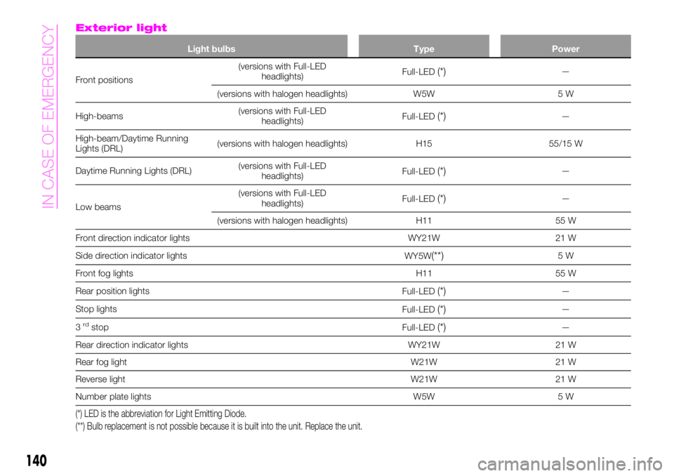
Exterior light
Light bulbs Type Power
Front positions(versions with Full-LED
headlights)Full-LED(*)—
(versions with halogen headlights) W5W 5 W
High-beams(versions with Full-LED
headlights)Full-LED
(*)—
High-beam/Daytime Running
Lights (DRL)(versions with halogen headlights) H15 55/15 W
Daytime Running Lights (DRL)(versions with Full-LED
headlights)Full-LED
(*)—
Low beams(versions with Full-LED
headlights)Full-LED
(*)—
(versions with halogen headlights) H11 55 W
Front direction indicator lights WY21W 21 W
Side direction indicator lights
WY5W
(**)5W
Front fog lights H11 55 W
Rear position lights
Full-LED
(*)—
Stop lights
Full-LED
(*)—
3
rdstop
Full-LED(*)—
Rear direction indicator lights WY21W 21 W
Rear fog light W21W 21 W
Reverse light W21W 21 W
Number plate lights W5W 5 W
(*) LED is the abbreviation for Light Emitting Diode.
(**) Bulb replacement is not possible because it is built into the unit. Replace the unit.
140
IN CASE OF EMERGENCY
Page 144 of 224
REPLACING EXTERIOR
LIGHT BULBS
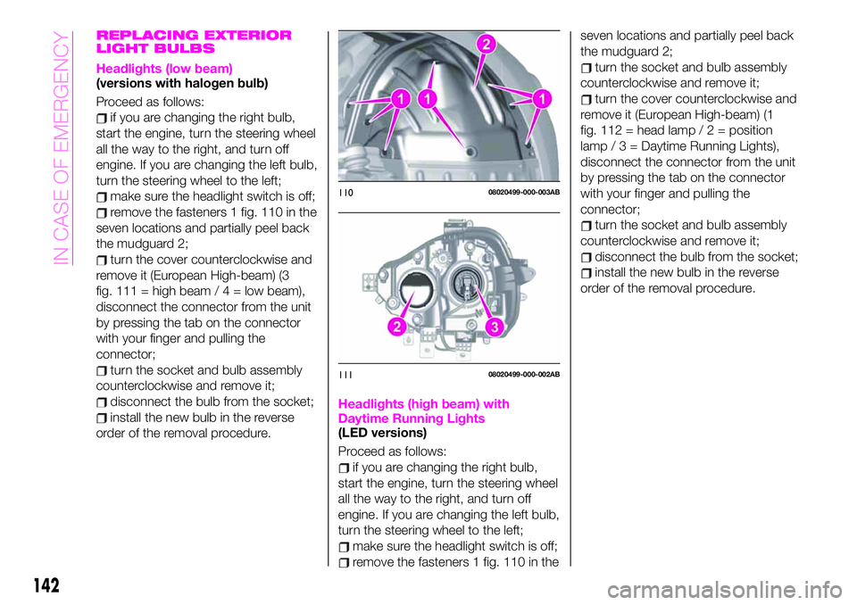
Headlights (low beam)(versions with halogen bulb)
Proceed as follows:
if you are changing the right bulb,
start the engine, turn the steering wheel
all the way to the right, and turn off
engine. If you are changing the left bulb,
turn the steering wheel to the left;
make sure the headlight switch is off;
remove the fasteners 1 fig. 110 in the
seven locations and partially peel back
the mudguard 2;
turn the cover counterclockwise and
remove it (European High-beam) (3
fig. 111 = high beam/4=lowbeam),
disconnect the connector from the unit
by pressing the tab on the connector
with your finger and pulling the
connector;
turn the socket and bulb assembly
counterclockwise and remove it;
disconnect the bulb from the socket;
install the new bulb in the reverse
order of the removal procedure.Headlights (high beam) with
Daytime Running Lights
(LED versions)
Proceed as follows:
if you are changing the right bulb,
start the engine, turn the steering wheel
all the way to the right, and turn off
engine. If you are changing the left bulb,
turn the steering wheel to the left;
make sure the headlight switch is off;
remove the fasteners 1 fig. 110 in theseven locations and partially peel back
the mudguard 2;
turn the socket and bulb assembly
counterclockwise and remove it;
turn the cover counterclockwise and
remove it (European High-beam) (1
fig. 112 = head lamp/2=position
lamp / 3 = Daytime Running Lights),
disconnect the connector from the unit
by pressing the tab on the connector
with your finger and pulling the
connector;
turn the socket and bulb assembly
counterclockwise and remove it;
disconnect the bulb from the socket;
install the new bulb in the reverse
order of the removal procedure.
11008020499-000-003AB
11108020499-000-002AB
142
IN CASE OF EMERGENCY
Page 145 of 224
Front direction indicator lights
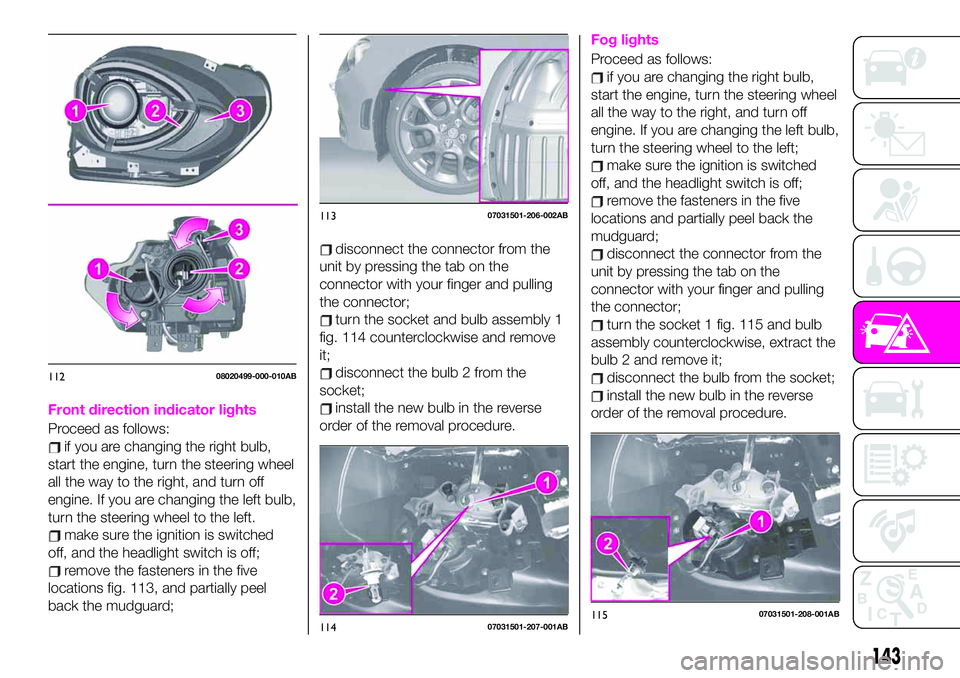
Proceed as follows:
if you are changing the right bulb,
start the engine, turn the steering wheel
all the way to the right, and turn off
engine. If you are changing the left bulb,
turn the steering wheel to the left.
make sure the ignition is switched
off, and the headlight switch is off;
remove the fasteners in the five
locations fig. 113, and partially peel
back the mudguard;
disconnect the connector from the
unit by pressing the tab on the
connector with your finger and pulling
the connector;
turn the socket and bulb assembly 1
fig. 114 counterclockwise and remove
it;
disconnect the bulb 2 from the
socket;
install the new bulb in the reverse
order of the removal procedure.
Fog lights
Proceed as follows:
if you are changing the right bulb,
start the engine, turn the steering wheel
all the way to the right, and turn off
engine. If you are changing the left bulb,
turn the steering wheel to the left;
make sure the ignition is switched
off, and the headlight switch is off;
remove the fasteners in the five
locations and partially peel back the
mudguard;
disconnect the connector from the
unit by pressing the tab on the
connector with your finger and pulling
the connector;
turn the socket 1 fig. 115 and bulb
assembly counterclockwise, extract the
bulb 2 and remove it;
disconnect the bulb from the socket;
install the new bulb in the reverse
order of the removal procedure.
11208020499-000-010AB
11307031501-206-002AB
11407031501-207-001AB11507031501-208-001AB
143
Page 146 of 224
Brake lights / Tail lights
Go to an Abarth Dealership when the
replacement of this lights is necessary.
Side direction indicator lights
Proceed as follows:
make sure the ignition is switched
off, and the headlight switch is off;
if you are changing the right bulb,
start the engine, turn the steering wheel
all the way to the right, and turn off
engine. If you are changing the left bulb,
turn the steering wheel to the left;
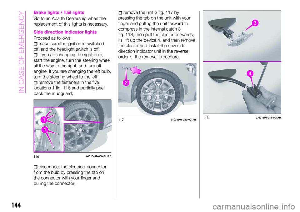
remove the fasteners in the five
locations 1 fig. 116 and partially peel
back the mudguard;
disconnect the electrical connector
from the bulb by pressing the tab on
the connector with your finger and
pulling the connector;
remove the unit 2 fig. 117 by
pressing the tab on the unit with your
finger and pulling the unit forward to
compress in the internal catch 3
fig. 118, then pull the cluster outwards;
lift up the device 4, and then remove
the cluster and install the new side
direction indicator unit in the reverse
order of the removal procedure.
11608020499-000-011AB
11707031501-210-001AB11807031501-211-001AB
144
IN CASE OF EMERGENCY
Page 148 of 224
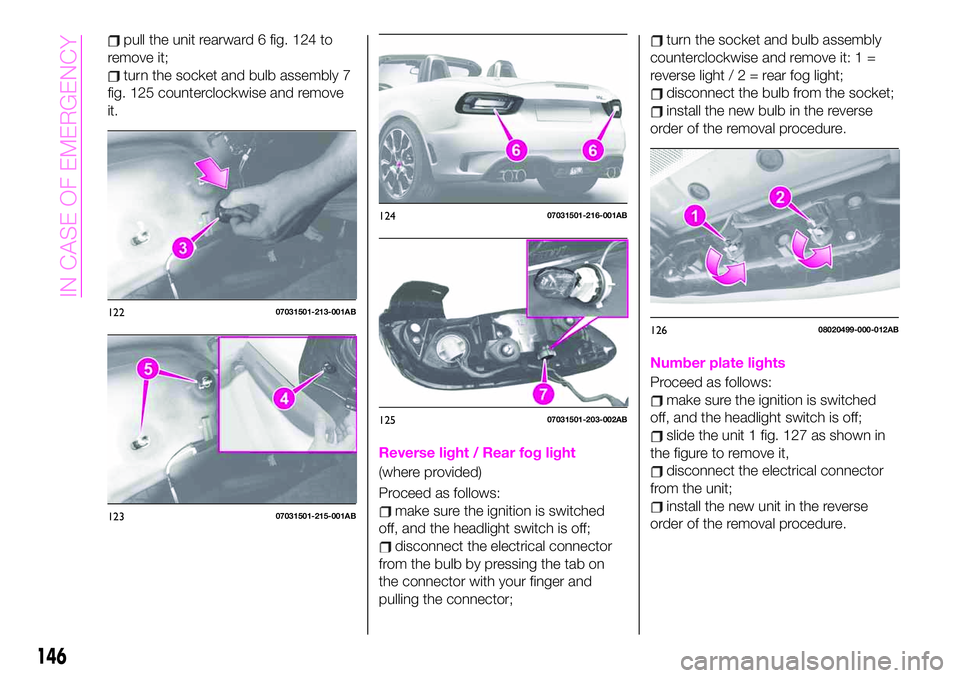
pull the unit rearward 6 fig. 124 to
remove it;
turn the socket and bulb assembly 7
fig. 125 counterclockwise and remove
it.
Reverse light / Rear fog light
(where provided)
Proceed as follows:
make sure the ignition is switched
off, and the headlight switch is off;
disconnect the electrical connector
from the bulb by pressing the tab on
the connector with your finger and
pulling the connector;
turn the socket and bulb assembly
counterclockwise and remove it: 1 =
reverse light/2=rearfoglight;
disconnect the bulb from the socket;
install the new bulb in the reverse
order of the removal procedure.
Number plate lights
Proceed as follows:
make sure the ignition is switched
off, and the headlight switch is off;
slide the unit 1 fig. 127 as shown in
the figure to remove it,
disconnect the electrical connector
from the unit;
install the new unit in the reverse
order of the removal procedure.
12207031501-213-001AB
12307031501-215-001AB
12407031501-216-001AB
12507031501-203-002AB
12608020499-000-012AB
146
IN CASE OF EMERGENCY