key Abarth 500 2010 Owner handbook (in English)
[x] Cancel search | Manufacturer: ABARTH, Model Year: 2010, Model line: 500, Model: Abarth 500 2010Pages: 170, PDF Size: 3.04 MB
Page 3 of 170
2
SAFETY
DEVICES
CORRECT USE
OF THE
CAR
WARNING
LIGHTS AND
MESSAGES
IN AN
EMERGENCY
CAR
MAINTENANCE
TECHNICAL
SPECIFICATIONS
INDEX
YOUR CARDASHBOARD ...................................................................... 3
SYMBOLS ............................................................................... 4
THE FIAT CODE SYSTEM.................................................. 4
THE KEYS .............................................................................. 5
INSTRUMENT PANEL AND ONBOARD
INSTRUMENTS..................................................................... 9
MULTIFUNCTIONAL DISPLAY AND
RECONFIGURABLE MULTIFUNCTIONAL DISPLAY 12
TRIP COMPUTER ................................................................ 21
SEATS ...................................................................................... 23
HEAD RESTRAINTS.............................................................24
STEERING WHEEL .............................................................. 25
REARVIEW MIRRORS......................................................... 26
CLIMATE COMFORT.......................................................... 27
HEATING AND VENTILATION...................................... 28
MANUAL CLIMATE CONTROL SYSTEM .................... 29
AUTOMATIC CLIMATE CONTROL SYSTEM............. 31
EXTERNAL LIGHTS............................................................. 34
WINDOW WASHING....................................................... 35CEILING LIGHTS ................................................................. 36
CONTROLS........................................................................... 37
INTERIOR FITTINGS........................................................... 39
SUNROOF.............................................................................. 41
DOORS .................................................................................. 43
POWER WINDOWS........................................................... 45
BOOT ......................................................................................46
BONNET................................................................................. 49
ROOF RACK/SKI RACK .................................................... 51
HEADLIGHTS........................................................................ 51
ABS SYSTEM ......................................................................... 53
ESP SYSTEM ........................................................................... 54
EOBD SYSTEM ..................................................................... 57
“DUALDRIVE” ELECTRIC POWER
STEERING SYSTEM ............................................................. 58
SOUND SYSTEM.................................................................. 59
AT THE FILLING STATION ............................................. 61
PROTECTING THE ENVIRONMENT............................. 62
Y
Y Y Y
O O O O
U U U U
R R R R
C C C C
A A A A
R R R R
001-022 ABARTH 500 GB 29-04-2009 9:40 Pagina 2
Page 5 of 170
4
SAFETY
DEVICES
CORRECT USE
OF THE
CAR
WARNING
LIGHTS AND
MESSAGES
IN AN
EMERGENCY
CAR
MAINTENANCE
TECHNICAL
SPECIFICATIONS
INDEX
YOUR CAR
Warning light Ycoming on when
driving
❒If the warning light Yturns on, this
means that the system is running a self-
test (such as following a voltage drop).
❒If the issue persists, contact the Abarth
Dealership .
SYMBOLS
Special coloured labels have been attached
near or actually on some of the compo-
nents of your car. These labels bear sym-
bols that remind you of the precautions
to be taken as regards that particular com-
ponent.
The inner surface of the engine bonnet in-
cludes a label with the different symbols
used.
THE FIAT CODE SYSTEM
This is an electrical engine locking system
which increases protection from attempt-
ed theft of the car. It is automatically acti-
vated when the ignition key is extracted.
Each time the car is started turning the ig-
nition key to MAR, the Fiat CODE system
control unit sends a recognition code to
the engine control unit to deactivate the in-
hibitor.
If, during ignition, the code is not correctly
recognized, the light
Ylights up on the
instrument panel.
In this case, turn the key to the STOPpo-
sition and then to the MARposition; if it
is still locked, try again with the other keys
that come with the vehicle. If you have
still not managed to start the engine, con-
tact an Abarth Dealership.
IMPORTANT Each key has its own code
which must be stored by the system ECU.
Contact the Abarth Dealership to have
new keys (up to eight) stored with the
code.The electronic components
inside the key may be dam-
aged if the key is submitted to
sharp knocks.
001-022 ABARTH 500 GB 29-04-2009 9:40 Pagina 4
Page 6 of 170
5
SAFETY
DEVICES
CORRECT USE
OF THE
CAR
WARNING
LIGHTS AND
MESSAGES
IN AN
EMERGENCY
CAR
MAINTENANCE
TECHNICAL
SPECIFICATIONS
INDEX
YOUR CAR
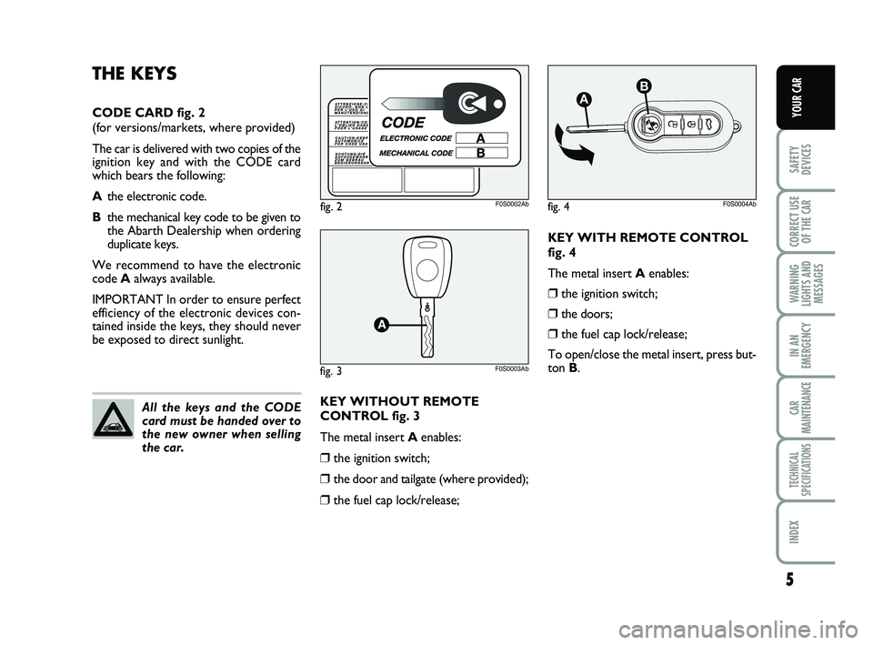
KEY WITH REMOTE CONTROL
fig. 4
The metal insert Aenables:
❒the ignition switch;
❒the doors;
❒the fuel cap lock/release;
To open/close the metal insert, press but-
ton B.
fig. 2F0S0002Ab
fig. 3F0S0003Ab
All the keys and the CODE
card must be handed over to
the new owner when selling
the car.
THE KEYS
CODE CARD fig. 2
(for versions/markets, where provided)
The car is delivered with two copies of the
ignition key and with the CODE card
which bears the following:
Athe electronic code.
Bthe mechanical key code to be given to
the Abarth Dealership when ordering
duplicate keys.
We recommend to have the electronic
code Aalways available.
IMPORTANT In order to ensure perfect
efficiency of the electronic devices con-
tained inside the keys, they should never
be exposed to direct sunlight.
KEY WITHOUT REMOTE
CONTROL fig. 3
The metal insert Aenables:
❒the ignition switch;
❒the door and tailgate (where provided);
❒the fuel cap lock/release;
fig. 4
AB
F0S0004Ab
001-022 ABARTH 500 GB 29-04-2009 9:40 Pagina 5
Page 8 of 170
7
SAFETY
DEVICES
CORRECT USE
OF THE
CAR
WARNING
LIGHTS AND
MESSAGES
IN AN
EMERGENCY
CAR
MAINTENANCE
TECHNICAL
SPECIFICATIONS
INDEX
YOUR CAR
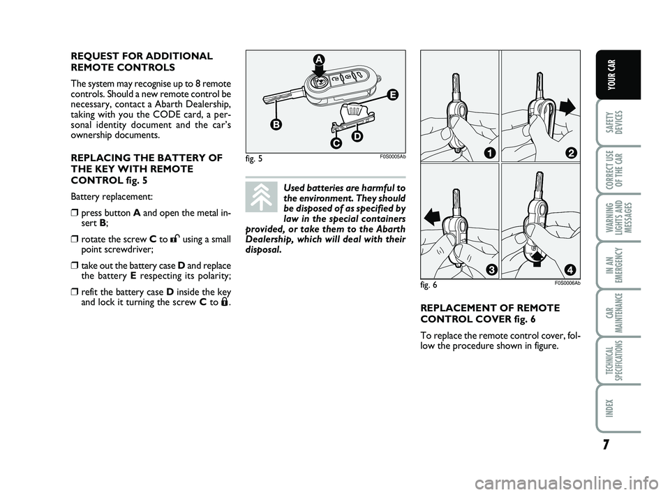
REPLACEMENT OF REMOTE
CONTROL COVER fig. 6
To replace the remote control cover, fol-
low the procedure shown in figure. REQUEST FOR ADDITIONAL
REMOTE CONTROLS
The system may recognise up to 8 remote
controls. Should a new remote control be
necessary, contact a Abarth Dealership,
taking with you the CODE card, a per-
sonal identity document and the car’s
ownership documents.
REPLACING THE BATTERY OF
THE KEY WITH REMOTE
CONTROL fig. 5
Battery replacement:
❒press button Aand open the metal in-
sert B;
❒rotate the screw Cto :using a small
point screwdriver;
❒take out the battery case Dand replace
the battery Erespecting its polarity;
❒refit the battery case Dinside the key
and lock it turning the screw Cto Á.
fig. 5F0S0005Ab
fig. 6F0S0006Ab
Used batteries are harmful to
the environment. They should
be disposed of as specified by
law in the special containers
provided, or take them to the Abarth
Dealership, which will deal with their
disposal.
001-022 ABARTH 500 GB 29-04-2009 9:40 Pagina 7
Page 9 of 170
8
SAFETY
DEVICES
CORRECT USE
OF THE
CAR
WARNING
LIGHTS AND
MESSAGES
IN AN
EMERGENCY
CAR
MAINTENANCE
TECHNICAL
SPECIFICATIONS
INDEX
YOUR CAR
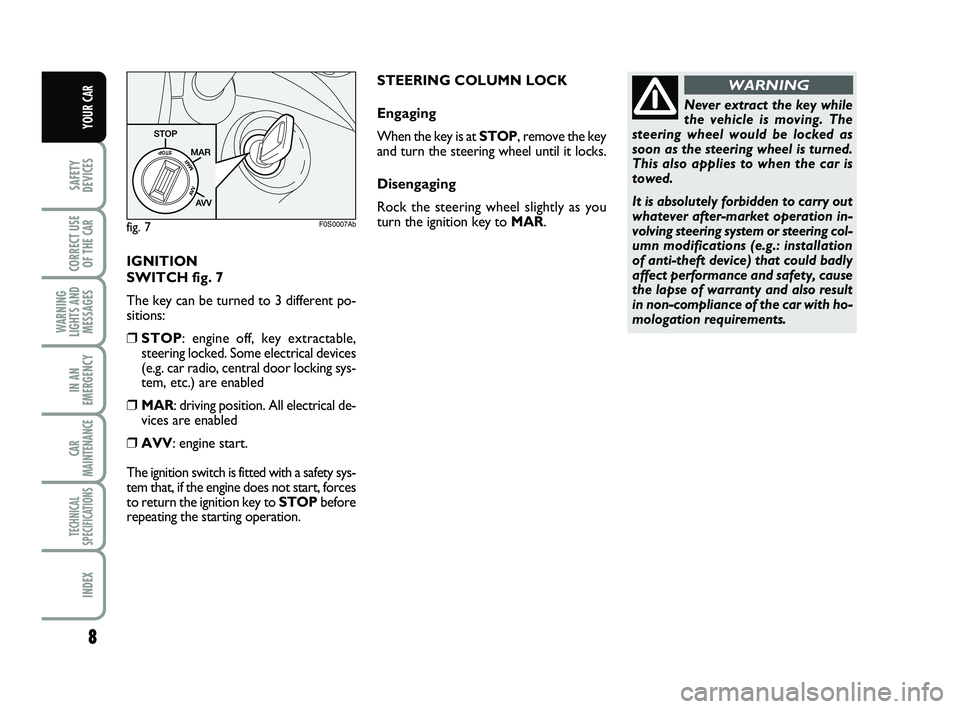
IGNITION
SWITCH fig. 7
The key can be turned to 3 different po-
sitions:
❒STOP: engine off, key extractable,
steering locked. Some electrical devices
(e.g. car radio, central door locking sys-
tem, etc.) are enabled
❒MAR: driving position. All electrical de-
vices are enabled
❒AVV: engine start.
The ignition switch is fitted with a safety sys-
tem that, if the engine does not start, forces
to return the ignition key to STOPbefore
repeating the starting operation.
Never extract the key while
the vehicle is moving. The
steering wheel would be locked as
soon as the steering wheel is turned.
This also applies to when the car is
towed.
It is absolutely forbidden to carry out
whatever after-market operation in-
volving steering system or steering col-
umn modifications (e.g.: installation
of anti-theft device) that could badly
affect performance and safety, cause
the lapse of warranty and also result
in non-compliance of the car with ho-
mologation requirements.
WARNING
fig. 7F0S0007Ab
STEERING COLUMN LOCK
Engaging
When the key is at STOP, remove the key
and turn the steering wheel until it locks.
Disengaging
Rock the steering wheel slightly as you
turn the ignition key to MAR.
001-022 ABARTH 500 GB 29-04-2009 9:40 Pagina 8
Page 21 of 170
20
SAFETY
DEVICES
CORRECT USE
OF THE
CAR
WARNING
LIGHTS AND
MESSAGES
IN AN
EMERGENCY
CAR
MAINTENANCE
TECHNICAL
SPECIFICATIONS
INDEX
YOUR CAR
NoteThe “Service Schedule” requires the
car to be serviced every 30,000 km (or
18,000 mi); this indication will appear au-
tomatically with the key on MARwhen
there are 2,000 km left (or equivalent dis-
tance in miles) and will be presented au-
tomatically every 200 km (or equivalent
distance in miles). The indications will ap-
pear more frequently where there are 200
km left. The indication will appear in kilo-
metres or miles according to the settings.
When the next scheduled service opera-
tion is approaching, the message “Service”
will appear on the display followed by the
number of kilometres or miles left when
the key is turned to MAR. Go to the
Abarth Dealership where the “Scheduled
Service” operations will be performed and
the message will be reset.Passenger bag
Front passenger’s airbag and
side bag activation/deactivation
(for versions/markets, where provided)
This function enables to activate/deacti-
vate the front passenger’s air bag.
Proceed as follows:
– press button MENU
ESCand, after dis-
playing the message (Bag pass: Off) (to dis-
able) or (Bag pass: On) (to enable) press-
ing buttons
+and –, press again button
MENU ESC;
- the confirmation request message will be
displayed;
- press buttons
+or –to select (Yes)
(confirming activation/deactivation) or
(No) (to abort);
- briefly press MENU
ESCto confirm set-
ting and go back to the menu screen or
press the button for long to go back to the
standard screen without storing settings.Daylights (D.R.L.)
This function enables to activate/deacti-
vate the daylight light.
Proceed as follows to switch this function
on or off:
– briefly press button MENU
ESCto dis-
play the three sub-menus;
– briefly press button MENU
ESC: (On)
or (Off) will flash on the display (accord-
ing to previous setting);
– press button
+or –for setting;
– briefly press button MENU
ESCto go
back to the menu screen or press the but-
ton for long to go back to the standard
screen without storing settings;
– hold MENU
ESCpressed to go back to
the standard screen or main menu accord-
ing to the points of the menu where you are
at.
Exit Menu
This is the last function that closes the cir-
cular setting cycle listed in the initial menu
screen.
Briefly press button MENU
ESCto go
back to the standard screen without stor-
ing settings.
Press button
–to return to the first menu
option (Speed Beep).
001-022 ABARTH 500 GB 29-04-2009 9:40 Pagina 20
Page 22 of 170
21
SAFETY
DEVICES
CORRECT USE
OF THE
CAR
WARNING
LIGHTS AND
MESSAGES
IN AN
EMERGENCY
CAR
MAINTENANCE
TECHNICAL
SPECIFICATIONS
INDEX
YOUR CAR
TRIP COMPUTER
General features
The “Trip computer” is used to display in-
formation on car operation when the key
is turned to MAR. This function allows to
define two separate trips called “Trip A”
and “Trip B” for monitoring the car’s
“complete mission” in a reciprocally in-
dependent manner.
Both functions are resettable (reset - start
of new mission).
“Trip A” shall be used to display the fig-
ures relating to:
– Range
– Trip distance
– Average consumption
– Instant consumption
– Average speed
– Travel time (driving time).“Trip B” shall be used to display the fig-
ures relating to:
– Trip distance B
– Average consumption B
– Average speed B
– Travel time B (driving time).
Note“Trip B” functions may be exclud-
ed (see “Trip B on”). “Range” and “In-
stantaneous consumption” cannot be re-
set.
Values displayed
Range
The distance that can be travelled with the
fuel in the tank is displayed, with the the-
ory that driving will continue in the same
conditions. The display will show the read-
ing “----” when the following events take
place:
– value lower than 50 km (or 30 mi)
– the car is parked with the engine run-
ning for a long time.IMPORTANT The range depends on sev-
eral factors: driving style (see “Driving
style” in “Starting and driving”), type of
route (motorway, urban cycle, mountain
roads, etc…), conditions of use of the car
(load, tyre pressure, etc…). Trip planning
must take into account the above notes.
Distance travelled
This value shows the distance covered
from the start of the new mission.
Average consumption
This value shows the approximate aver-
age consumption from the start of the
new mission.
Instant consumption
This indicates the fuel consumption. The val-
ue is constantly updated. The message
“----” will appear on the display if the car is
parked with the engine running.
001-022 ABARTH 500 GB 29-04-2009 9:40 Pagina 21
Page 23 of 170
22
SAFETY
DEVICES
CORRECT USE
OF THE
CAR
WARNING
LIGHTS AND
MESSAGES
IN AN
EMERGENCY
CAR
MAINTENANCE
TECHNICAL
SPECIFICATIONS
INDEX
YOUR CAR
Average speed
This value shows the car average speed as
a function of the overall time elapsed since
the start of the new mission.
Travel time
This value shows the time elapsed since
the start of the new mission.
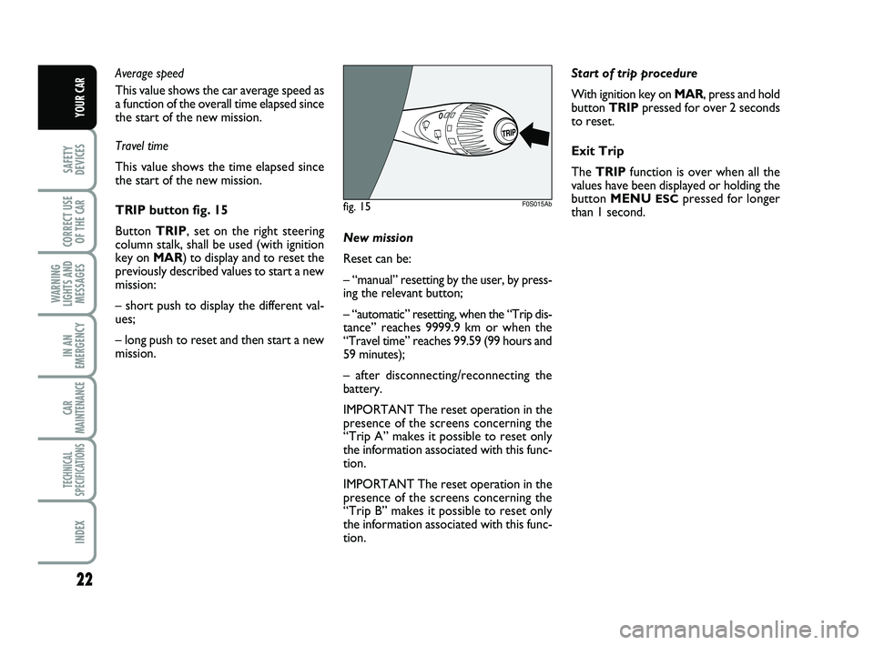
TRIP button fig. 15
Button TRIP, set on the right steering
column stalk, shall be used (with ignition
key on MAR) to display and to reset the
previously described values to start a new
mission:
– short push to display the different val-
ues;
– long push to reset and then start a new
mission.New mission
Reset can be:
– “manual” resetting by the user, by press-
ing the relevant button;
– “automatic” resetting, when the “Trip dis-
tance” reaches 9999.9 km or when the
“Travel time” reaches 99.59 (99 hours and
59 minutes);
– after disconnecting/reconnecting the
battery.
IMPORTANT The reset operation in the
presence of the screens concerning the
“Trip A” makes it possible to reset only
the information associated with this func-
tion.
IMPORTANT The reset operation in the
presence of the screens concerning the
“Trip B” makes it possible to reset only
the information associated with this func-
tion.Start of trip procedure
With ignition key on MAR, press and hold
button TRIPpressed for over 2 seconds
to reset.
Exit Trip
The TRIPfunction is over when all the
values have been displayed or holding the
button MENU
ESCpressed for longer
than 1 second.fig. 15F0S015Ab
001-022 ABARTH 500 GB 29-04-2009 9:40 Pagina 22
Page 35 of 170
34
SAFETY
DEVICES
CORRECT USE
OF THE
CAR
WARNING
LIGHTS AND
MESSAGES
IN AN
EMERGENCY
CAR
MAINTENANCE
TECHNICAL
SPECIFICATIONS
INDEX
YOUR CAR
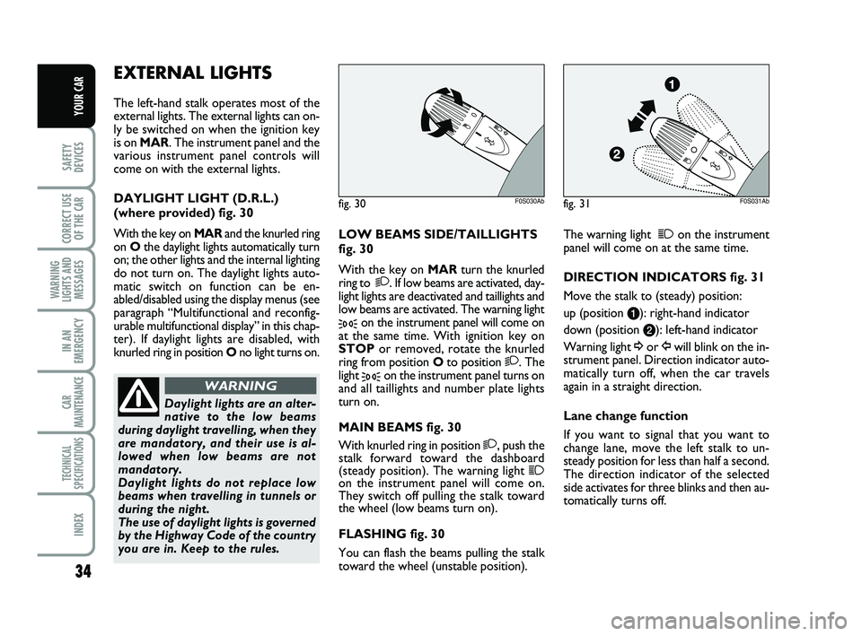
LOW BEAMS SIDE/TAILLIGHTS
fig. 30
With the key on MAR turn the knurled
ring to
2. If low beams are activated, day-
light lights are deactivated and taillights and
low beams are activated. The warning light
3on the instrument panel will come on
at the same time. With ignition key on
STOPor removed, rotate the knurled
ring from position Oto position
2. The
light
3on the instrument panel turns on
and all taillights and number plate lights
turn on.
MAIN BEAMS fig. 30
With knurled ring in position
2, push the
stalk forward toward the dashboard
(steady position). The warning light
1on the instrument panel will come on.
They switch off pulling the stalk toward
the wheel (low beams turn on).
FLASHING fig. 30
You can flash the beams pulling the stalk
toward the wheel (unstable position). The warning light
1on the instrument
panel will come on at the same time.
DIRECTION INDICATORS fig. 31
Move the stalk to (steady) position:
up (position a): right-hand indicator
down (position b): left-hand indicator
Warning light ¥or Îwill blink on the in-
strument panel. Direction indicator auto-
matically turn off, when the car travels
again in a straight direction.
Lane change function
If you want to signal that you want to
change lane, move the left stalk to un-
steady position for less than half a second.
The direction indicator of the selected
side activates for three blinks and then au-
tomatically turns off.
EXTERNAL LIGHTS
The left-hand stalk operates most of the
external lights. The external lights can on-
ly be switched on when the ignition key
is on MAR. The instrument panel and the
various instrument panel controls will
come on with the external lights.
DAYLIGHT LIGHT (D.R.L.)
(where provided) fig. 30
With the key on MARand the knurled ring
on Othe daylight lights automatically turn
on; the other lights and the internal lighting
do not turn on. The daylight lights auto-
matic switch on function can be en-
abled/disabled using the display menus (see
paragraph “Multifunctional and reconfig-
urable multifunctional display” in this chap-
ter). If daylight lights are disabled, with
knurled ring in position Ono light turns on.
fig. 30F0S030Abfig. 31F0S031Ab
Daylight lights are an alter-
native to the low beams
during daylight travelling, when they
are mandatory, and their use is al-
lowed when low beams are not
mandatory.
Daylight lights do not replace low
beams when travelling in tunnels or
during the night.
The use of daylight lights is governed
by the Highway Code of the country
you are in. Keep to the rules.
WARNING
023-045 ABARTH 500 GB 29-04-2009 9:41 Pagina 34
Page 36 of 170
35
SAFETY
DEVICES
CORRECT USE
OF THE
CAR
WARNING
LIGHTS AND
MESSAGES
IN AN
EMERGENCY
CAR
MAINTENANCE
TECHNICAL
SPECIFICATIONS
INDEX
YOUR CAR
WINDOW WASHING
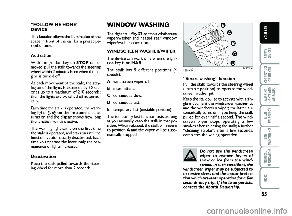
The right stalk fig. 32controls windscreen
wiper/washer and heated rear window
wiper/washer operation.
WINDSCREEN WASHER/WIPER
The device can work only when the igni-
tion key is on MAR.
The stalk has 5 different positions (4
speeds):
Awindscreen wiper off.
Bintermittent.
Ccontinuous slow.
Dcontinuous fast.
Etemporary fast (unstable position).
The temporary fast function lasts as long
as you manually keep the stalk in that po-
sition. When released, the stalk will return
to position Aand the wiper will be auto-
matically stopped.“Smart washing” function
Pull the stalk towards the steering wheel
(unstable position) to operate the wind-
screen washer jet.
Keep the stalk pulled to activate with a sin-
gle movement the windscreen washer jet
and the windscreen wiper; the latter au-
tomatically turns on if you keep the stalk
pulled for over half a second. The wind-
screen wiper stops operating a few
strokes after releasing the stalk; a further
“cleaning stroke”, after a few seconds,
completes the wiping operation. “FOLLOW ME HOME”
DEVICE
This function allows the illumination of the
space in front of the car for a preset pe-
riod of time.
Activation
With the ignition key on STOPor re-
moved, pull the stalk towards the steering
wheel within 2 minutes from when the en-
gine is turned off.
At each movement of the stalk, the stay-
ing on of the lights is extended by 30 sec-
onds up to a maximum of 210 seconds;
then the lights are switched off automati-
cally.
Each time the stalk is operated, the warn-
ing light
3on the instrument panel
turns on and the display shows how long
the function remains active.
The warning light turns on the first time
the stalk is operated, and stays on until the
function is automatically deactivated. Each
time you operate the lever, only the per-
manence of lights increases.
Deactivation
Keep the stalk pulled towards the steer-
ing wheel for more than 2 seconds.
F0S032Abfig. 32
Do not use the windscreen
wiper to remove layers of
snow or ice from the wind-
screen. In such conditions, the
windscreen wiper may be subjected to
excessive stress and the motor protec-
tion which prevents operation for a few
seconds may trip. If the issue persists,
contact the Abarth Dealership.
023-045 ABARTH 500 GB 29-04-2009 9:41 Pagina 35