ESP Abarth 500 2016 Owner handbook (in English)
[x] Cancel search | Manufacturer: ABARTH, Model Year: 2016, Model line: 500, Model: Abarth 500 2016Pages: 215, PDF Size: 19.08 MB
Page 127 of 215

20) A quick burst on the accelerator
before turning off the engine
serves absolutely no practical
purpose; it wastes fuel and is
especially damaging to
turbocharged engines.
WARNING
96) It is dangerous to run the engine
in enclosed areas. The engine
takes in oxygen and releases
carbon dioxide, carbon monoxide
and other toxic gases.
97) Remember that the brake servo
and electric power steering are
not active until the engine is
started. A much greater effort will
therefore be required to use the
brake pedal or turn the steering
wheel.
PARKING
Proceed as follows:
❒stop the engine and engage the
handbrake;
❒engage a gear (first gear if parked
uphill or reverse if facing downhill)
and leave the wheels turned.
Block the wheels with a wedge or a
stone if the car is parked on a steep
slope.
Do not leave the ignition key on
MAR-ON to avoid draining the battery.
Always remove the key when you
leave the car.
98)
HANDBRAKE
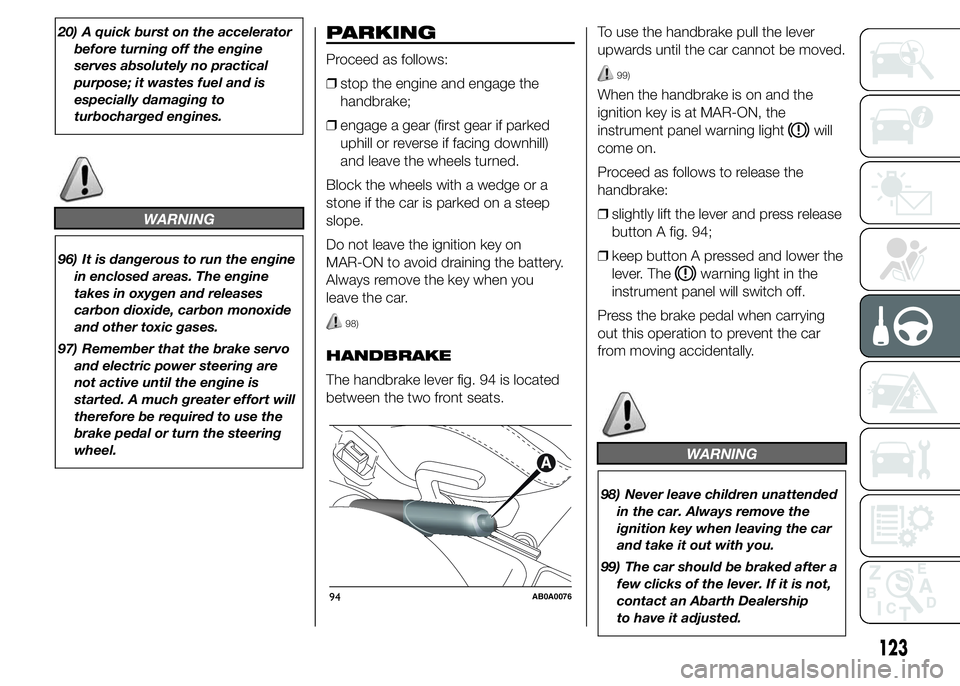
The handbrake lever fig. 94 is located
between the two front seats.To use the handbrake pull the lever
upwards until the car cannot be moved.
99)
When the handbrake is on and the
ignition key is at MAR-ON, the
instrument panel warning light
will
come on.
Proceed as follows to release the
handbrake:
❒slightly lift the lever and press release
button A fig. 94;
❒keep button A pressed and lower the
lever. The
warning light in the
instrument panel will switch off.
Press the brake pedal when carrying
out this operation to prevent the car
from moving accidentally.
WARNING
98) Never leave children unattended
in the car. Always remove the
ignition key when leaving the car
and take it out with you.
99) The car should be braked after a
few clicks of the lever. If it is not,
contact an Abarth Dealership
to have it adjusted.
94AB0A0076
123
Page 130 of 215

CONDITIONS OF USE
Cold starting
Short journeys and frequent cold starts
do not allow the engine to reach
optimum operating temperature. This
results in a significant increase in
consumption levels (from +15 to +30%
on the urban cycle) and emissions.
Traffic and road
conditions
High fuel consumption is caused by
heavy traffic, for instance when
travelling in a queue with frequent use
of low gears or in cities with many traffic
lights. Winding mountain roads and
rough road surfaces also adversely
affect consumption.
Stops in traffic
During prolonged hold-ups (e.g. level
crossings) switch off the engine.TOWING TRAILERS
IMPORTANT
INFORMATION
For towing caravans or trailers the car
must be fitted with a certified tow hook
and an adequate electrical system.
Installation should be carried out by
specialised personnel who will issue the
required papers for travelling on roads.
Install any specific and/or additional
door mirrors as specified by the
Highway Code.
Remember that when towing a trailer,
steep hills are harder to climb, braking
distances increase and overtaking
takes longer depending on the overall
weight of the trailer.
Engage a low gear when driving
downhill, rather than constantly using
the brake.
The weight the trailer exerts on the car
tow hook reduces the car's loading
capacity by the same amount. To make
sure that the maximum towable weight
is not exceeded (given in the car
registration document) account should
be taken of the fully laden trailer,
including accessories and luggage.Respect the speed limits specific to
each country for vehicles towing
trailers.
In any case, the top speed must not
exceed 100 km/h.
101) 102)
WARNING
101) The ABS with which the car is
equipped will not control the
braking system of the trailer.
Particular caution is therefore
required on slippery surfaces.
102) Never modify the braking
system of the car to control the
trailer brake. The trailer braking
system must be fully independent
of the car’s hydraulic system.
126
STARTING AND DRIVING
Page 139 of 215

REPLACING A BULB
GENERAL
INSTRUCTIONS
❒Before replacing a bulb check the
contacts for oxidation;
❒burnt bulbs must be replaced by
others of the same type and power;
❒always check the headlight beam
alignment after replacing a bulb;
❒when a light is not working, check
that the corresponding fuse is intact
before replacing a bulb. For the
location of fuses, refer to the
paragraph "Replacing fuses" in this
chapter.
114) 115)
25) 26)
IMPORTANT When the weather is cold
or damp or after heavy rain or washing,
the surface of headlights or rear lights
may steam up and/or form drops of
condensation on the inside. This is
a natural phenomenon due to the
difference in temperature and humidity
between the inside and the outside
of the glass which does not indicate a
fault and does not compromise the
normal operation of lighting devices.
The mist disappears quickly when the
lights are turned on, starting from
the centre of the diffuser, extending
progressively towards the edges.
135
Page 142 of 215

WARNING
114) Changes or repairs to the electrical system carried out incorrectly and without due consideration for the technical
specifications of the system may lead to malfunctioning and generate a fire hazard.
115) Halogen bulbs contain pressurised gas. If they break, glass fragments could fly everywhere.
IMPORTANT
25) Halogen bulbs must be handled by holding the metallic part only. Touching the transparent part of the bulb with
your fingers may reduce the intensity of the emitted light and even reduce the lifespan of the bulb. In the event of
accidental contact, wipe the bulb with a cloth moistened with alcohol and let the bulb dry.
26) Where possible, it is advisable to have bulbs changed at an Abarth Dealership. The correct operation and alignment
of the external lights are absolutely essential for the safety of the car and of compliance with the law.
138
IN AN EMERGENCY
Page 149 of 215

Engine compartment
fuse box
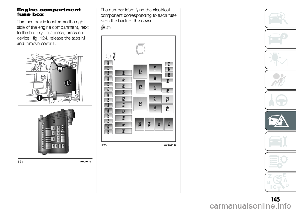
The fuse box is located on the right
side of the engine compartment, next
to the battery. To access, press on
device I fig. 124, release the tabs M
and remove cover L.The number identifying the electrical
component corresponding to each fuse
is on the back of the cover
.
27)
124AB0A0131
125AB0A0130
145
Page 155 of 215

127) The front and rear tow hooks
should be used only for
emergencies on the road. You are
allowed to tow the vehicle for
short distances using an
appropriate device in accordance
with the highway code (a rigid
bar), to move the vehicle on the
road in readiness for towing or
transport via a breakdown vehicle.
Tow hooks MUST NOT be used
to tow vehicles off the road or
where there are obstacles and/or
for towing operations using cables
or other non-rigid devices.
Respecting the above conditions,
towing must take place with two
vehicles (one towing, the other
towed) aligned as much as
possible along the same centre
line.128) Whilst towing, remember that
as the assistance of the brake
servo and the electric power
steering is not available, greater
force needs to be exerted on
the brake pedal and more effort is
required on the steering wheel.
Do not use flexible cables when
towing and avoid jerky
movements. While towing, make
sure that the trailer hitch does not
damage any components it is
touching. When towing the car,
you must comply with all specific
traffic regulations, both in terms
of the towing device and
behaviour on the road. Do not
start the engine while towing the
car.
129) Because of its conformation,
the car cannot be loaded onto
railway carriages and transported.
151
Page 164 of 215

ENGINE OIL
30)
3)
Check the oil level a few minutes (about
five) after the engine has stopped,
with the car parked on level ground.
Take out the engine oil dipstick B, clean
it with a lint-free cloth and reinsert it.
Extract the engine oil dipstick again and
check that the level is between the
MIN and MAX marks on the dipstick.
The range between the MIN and MAX
marks corresponds to about 1 litre
of oil.
If the oil level is near or under the MIN
mark, add oil through the filler A until
it reaches the MAX mark.
The oil level must never exceed the
MAX mark.
Engine oil consumption
The maximum engine oil consumption
is usually 400 grams every 1,000 km.
When the car is new, the engine needs
to be run in; therefore the engine oil
consumption can only be considered
stabilised after the first 5,000 -
6,000 km.IMPORTANT The oil consumption
depends on driving style and the
conditions under which the car is used.
IMPORTANT After adding or changing
the oil, let the engine run for a few
seconds and wait a few minutes after
switching it off before checking the
level.
ENGINE COOLANT
The coolant level must be checked
when the engine is cold and must
range between the MIN and MAX
marks on the reservoir.
If the level is too low, unscrew reservoir
cap C fig. 128 and add the fluid
described in the "Technical
specifications" chapter.
31)
132)
WINDSCREEN/REAR
WINDOW WASHER FLUID
Check fluid level through the reservoir.
If the level is too low, lift reservoir cap D
fig. 128 and add the fluid described in
the "Technical specifications" chapter.
After topping up, close cap D, making
sure it is correctly locked.BRAKE FLUID
Check that the fluid is at the maximum
level (the fluid level in the reservoir
must not exceed the MAX mark).
If the fluid level in the reservoir is too
low, undo reservoir cap E fig. 128 and
add the fluid described in the "Technical
specifications" chapter.
134) 135)
32)
IMPORTANT Carefully clean the cap of
the reservoir E and the surrounding
surface.
Take great care to ensure that
impurities do not enter the reservoir
when the cap is opened.
For topping-up, always use a funnel
with integrated filter with mesh equal to
or lower than 0.12 mm.
IMPORTANT Brake fluid is hygroscopic
(i.e. it absorbs moisture). For this
reason, if the car is mainly used in areas
with a high degree of atmospheric
humidity, the fluid must be replaced at
more frequent intervals than specified in
the "Scheduled Servicing Plan".
160
SERVICING AND MAINTENANCE
Page 176 of 215

IDENTIFICATION
DATA
The following identification codes are
printed and shown on the plates:
❒VIN plate.
❒Chassis marking.
❒Bodywork paint identification plate.
❒Engine marking.
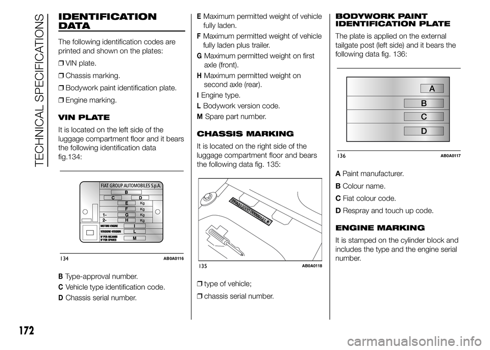
VIN PLATE
It is located on the left side of the
luggage compartment floor and it bears
the following identification data
fig. 134:
BType-approval number.
CVehicle type identification code.
DChassis serial number.
EMaximum permitted weight of vehicle
fully laden.
FMaximum permitted weight of vehicle
fully laden plus trailer.
GMaximum permitted weight on first
axle (front).
HMaximum permitted weight on
second axle (rear).
IEngine type.
LBodywork version code.
MSpare part number.
CHASSIS MARKING
It is located on the right side of the
luggage compartment floor and bears
the following data fig. 135:
❒type of vehicle;
❒chassis serial number.BODYWORK PAINT
IDENTIFICATION PLATE
The plate is applied on the external
tailgate post (left side) and it bears the
following data fig. 136:
APaint manufacturer.
BColour name.
CFiat colour code.
DRespray and touch up code.
ENGINE MARKING
It is stamped on the cylinder block and
includes the type and the engine serial
number.
134AB0A0116135AB0A0118
136AB0A0117
172
TECHNICAL SPECIFICATIONS
Page 178 of 215

ENGINE
GENERAL INFORMATION 1.4 TB PETROL ABARTH
Type code312A1000
CycleOtto
Number and position of cylinders 4 in line
Piston bore and stroke (mm) 72 x 84
Total cylinder capacity (cm
3) 1368
Compression ratio 9.8 : 1
Maximum power (EC) (kW) 99
Maximum power (EC) (HP) 135
corresponding engine speed (rpm) 5500
Maximum torque (EC) (Nm) 180 (*) / 206 (**)
corresponding engine speed (rpm) 2000
Spark plugsNGK IKR9F8
FuelUnleaded petrol 95 R.O.N.
(*) NORMAL
(**) SPORT
174
TECHNICAL SPECIFICATIONS
Page 185 of 215

CORRECT READING OF
THE RIM CODE
Examplefig. 137: 7.00 J
x17H2
7.00rim width in inches (1).
Jprofile of the flange (side projection
where the tyre bead rests) (2).
17rim nominal diameter in inches
(corresponds to diameter of the tyre
to be mounted) (3 = Ø).
H2shape and number of humps
(circumference measurement which
keeps the bead of Tubeless tyres
in position on the rim).RIM PROTECTOR TYRES
148)
WARNING
148) DO NOT fit wheel caps when
using integral wheel caps fixed
(with springs) to the steel rim and
after-sale tyres provided with
Rim Protector (fig. 138). Use of
unsuitable tyres and wheel caps
may cause sudden loss of tyre
pressure.
138AB0A0120
181