lock Abarth 500 2019 Owner handbook (in English)
[x] Cancel search | Manufacturer: ABARTH, Model Year: 2019, Model line: 500, Model: Abarth 500 2019Pages: 196, PDF Size: 3.53 MB
Page 34 of 196
Opening and closing the roof
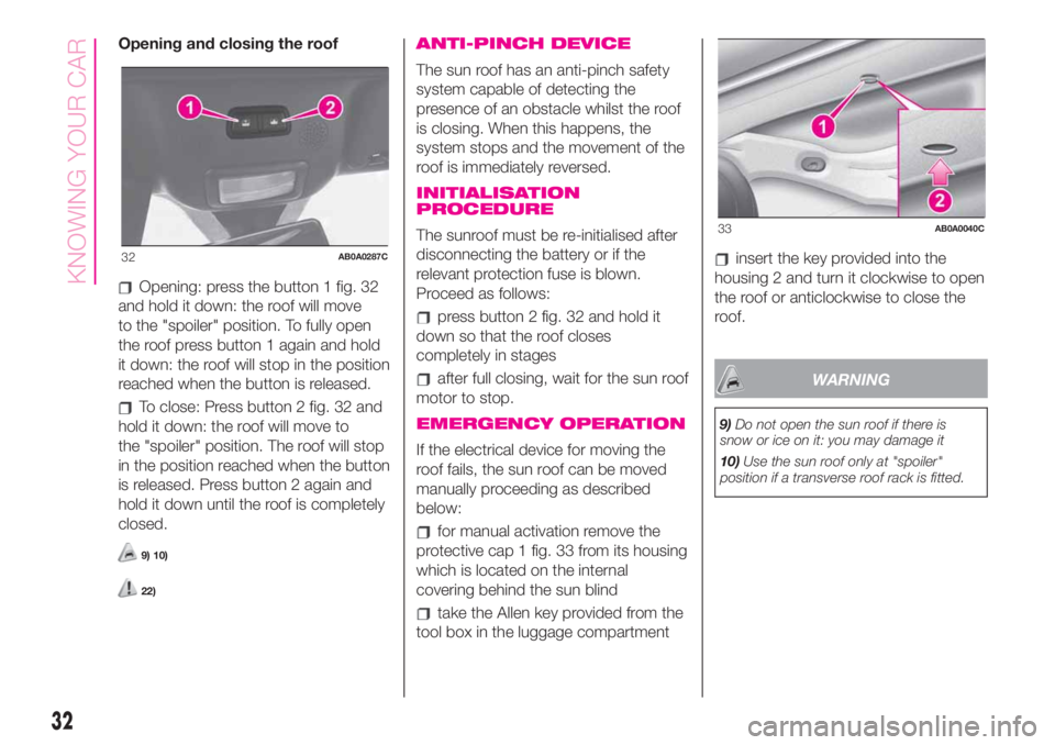
Opening: press the button 1 fig. 32
and hold it down: the roof will move
to the "spoiler" position. To fully open
the roof press button 1 again and hold
it down: the roof will stop in the position
reached when the button is released.
To close: Press button 2 fig. 32 and
hold it down: the roof will move to
the "spoiler" position. The roof will stop
in the position reached when the button
is released. Press button 2 again and
hold it down until the roof is completely
closed.
9) 10)
22)
ANTI-PINCH DEVICE
The sun roof has an anti-pinch safety
system capable of detecting the
presence of an obstacle whilst the roof
is closing. When this happens, the
system stops and the movement of the
roof is immediately reversed.
INITIALISATION
PROCEDURE
The sunroof must be re-initialised after
disconnecting the battery or if the
relevant protection fuse is blown.
Proceed as follows:
press button 2 fig. 32 and hold it
down so that the roof closes
completely in stages
after full closing, wait for the sun roof
motor to stop.
EMERGENCY OPERATION
If the electrical device for moving the
roof fails, the sun roof can be moved
manually proceeding as described
below:
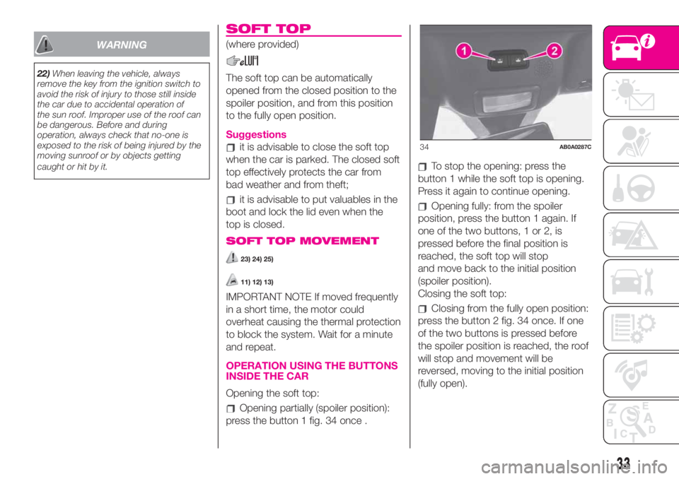
for manual activation remove the
protective cap 1 fig. 33 from its housing
which is located on the internal
covering behind the sun blind
take the Allen key provided from the
tool box in the luggage compartment
insert the key provided into the
housing 2 and turn it clockwise to open
the roof or anticlockwise to close the
roof.
WARNING
9)Do not open the sun roof if there is
snow or ice on it: you may damage it
10)Use the sun roof only at "spoiler"
position if a transverse roof rack is fitted.
32AB0A0287C
33AB0A0040C
32
KNOWING YOUR CAR
Page 35 of 196
WARNING
22)When leaving the vehicle, always
remove the key from the ignition switch to
avoid the risk of injury to those still inside
the car due to accidental operation of
the sun roof. Improper use of the roof can
be dangerous. Before and during
operation, always check that no-one is
exposed to the risk of being injured by the
moving sunroof or by objects getting
caught or hit by it.
SOFT TOP
(where provided)
The soft top can be automatically
opened from the closed position to the
spoiler position, and from this position
to the fully open position.
Suggestions
it is advisable to close the soft top
when the car is parked. The closed soft
top effectively protects the car from
bad weather and from theft;
it is advisable to put valuables in the
boot and lock the lid even when the
top is closed.
SOFT TOP MOVEMENT
23) 24) 25)
11) 12) 13)
IMPORTANT NOTE If moved frequently
in a short time, the motor could
overheat causing the thermal protection
to block the system. Wait for a minute
and repeat.
OPERATION USING THE BUTTONS
INSIDE THE CAR
Opening the soft top:
Opening partially (spoiler position):
press the button 1 fig. 34 once .
To stop the opening: press the
button 1 while the soft top is opening.
Press it again to continue opening.
Opening fully: from the spoiler
position, press the button 1 again. If
one of the two buttons, 1 or 2, is
pressed before the final position is
reached, the soft top will stop
and move back to the initial position
(spoiler position).
Closing the soft top:
Closing from the fully open position:
press the button 2 fig. 34 once. If one
of the two buttons is pressed before
the spoiler position is reached, the roof
will stop and movement will be
reversed, moving to the initial position
(fully open).
34AB0A0287C
33
Page 37 of 196
EMERGENCY OPERATION
If the buttons fail, the soft top can be
moved manually proceeding as
described below:
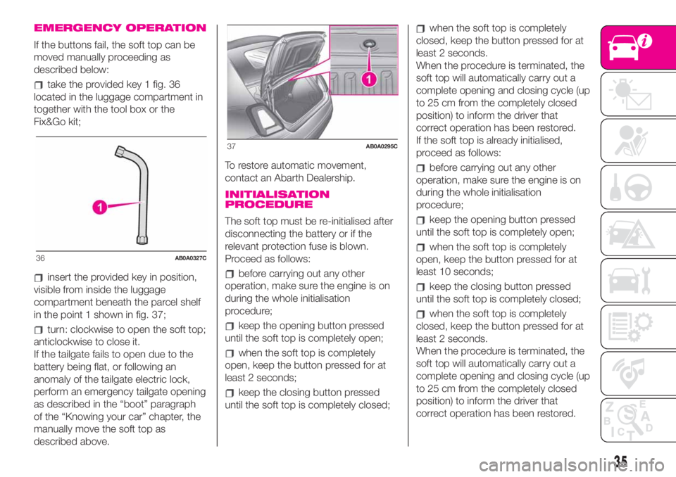
take the provided key 1 fig. 36
located in the luggage compartment in
together with the tool box or the
Fix&Go kit;
insert the provided key in position,
visible from inside the luggage
compartment beneath the parcel shelf
in the point 1 shown in fig. 37;
turn: clockwise to open the soft top;
anticlockwise to close it.
If the tailgate fails to open due to the
battery being flat, or following an
anomaly of the tailgate electric lock,
perform an emergency tailgate opening
as described in the “boot” paragraph
of the “Knowing your car” chapter, the
manually move the soft top as
described above.To restore automatic movement,
contact an Abarth Dealership.
INITIALISATION
PROCEDURE
The soft top must be re-initialised after
disconnecting the battery or if the
relevant protection fuse is blown.
Proceed as follows:
before carrying out any other
operation, make sure the engine is on
during the whole initialisation
procedure;
keep the opening button pressed
until the soft top is completely open;
when the soft top is completely
open, keep the button pressed for at
least 2 seconds;
keep the closing button pressed
until the soft top is completely closed;
when the soft top is completely
closed, keep the button pressed for at
least 2 seconds.
When the procedure is terminated, the
soft top will automatically carry out a
complete opening and closing cycle (up
to 25 cm from the completely closed
position) to inform the driver that
correct operation has been restored.
If the soft top is already initialised,
proceed as follows:
before carrying out any other
operation, make sure the engine is on
during the whole initialisation
procedure;
keep the opening button pressed
until the soft top is completely open;
when the soft top is completely
open, keep the button pressed for at
least 10 seconds;
keep the closing button pressed
until the soft top is completely closed;
when the soft top is completely
closed, keep the button pressed for at
least 2 seconds.
When the procedure is terminated, the
soft top will automatically carry out a
complete opening and closing cycle (up
to 25 cm from the completely closed
position) to inform the driver that
correct operation has been restored.
36AB0A0327C
37AB0A0295C
35
Page 38 of 196
WIND STOP
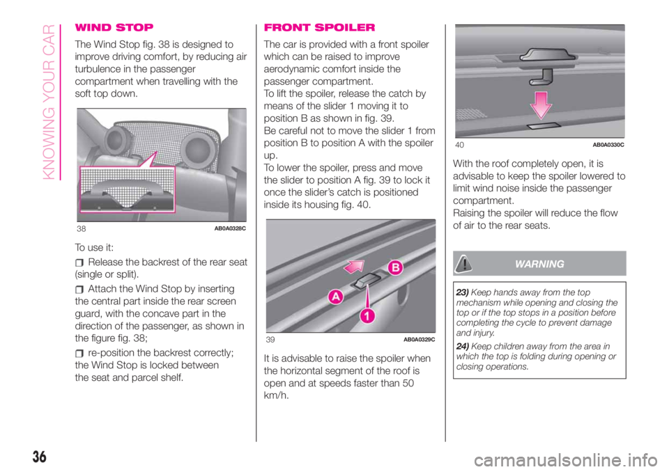
The Wind Stop fig. 38 is designed to
improve driving comfort, by reducing air
turbulence in the passenger
compartment when travelling with the
soft top down.
To use it:
Release the backrest of the rear seat
(single or split).
Attach the Wind Stop by inserting
the central part inside the rear screen
guard, with the concave part in the
direction of the passenger, as shown in
the figure fig. 38;
re-position the backrest correctly;
the Wind Stop is locked between
the seat and parcel shelf.
FRONT SPOILER
The car is provided with a front spoiler
which can be raised to improve
aerodynamic comfort inside the
passenger compartment.
To lift the spoiler, release the catch by
means of the slider 1 moving it to
position B as shown in fig. 39.
Be careful not to move the slider 1 from
position B to position A with the spoiler
up.
To lower the spoiler, press and move
the slider to position A fig. 39 to lock it
once the slider’s catch is positioned
inside its housing fig. 40.
It is advisable to raise the spoiler when
the horizontal segment of the roof is
open and at speeds faster than 50
km/h.With the roof completely open, it is
advisable to keep the spoiler lowered to
limit wind noise inside the passenger
compartment.
Raising the spoiler will reduce the flow
of air to the rear seats.
WARNING
23)Keep hands away from the top
mechanism while opening and closing the
top or if the top stops in a position before
completing the cycle to prevent damage
and injury.
24)Keep children away from the area in
which the top is folding during opening or
closing operations.
38AB0A0328C
39AB0A0329C
40AB0A0330C
36
KNOWING YOUR CAR
Page 39 of 196
25)When leaving the car, always remove
the key from the ignition device to avoid the
risk of injury due to accidental operation
of the soft top: improper use of the roof
can be dangerous. Before and during
operation, always check that no-one is at
risk of being injured by the moving soft top
roof or by objects getting caught and
dragged by it.
WARNING
11)Never open the top in presence of
snow or ice to prevent damage.
12)Do not place objects on the rear
window shelf to prevent damage while the
top is closing.
13)Loads may not be secured on the roof.
ENGINE BONNET
OPENING
Proceed as follows:
pull lever 1 fig. 41 in the direction
indicated by the arrow;
move the lever 2 fig. 42 to the right
as shown in the figure;
lift the bonnet and, at the same time,
release the supporting rod 3 fig. 43
from its catch 4, then insert the end of
the rod into housing 5 in the bonnet
(large hole) and push to safety position
(small hole), as shown in the figure.
26) 27) 28) 30)
CLOSING
Proceed as follows:
hold the bonnet up with one hand
and with the other remove the stay
3 fig. 43 from the housing 5 and put it
back in its locking device 4;
41AB0A0051C
42AB0A0052C
43AB0A0053C
37
Page 40 of 196
lower the bonnet to approximately
20 centimetres above the engine
compartment and let it come down.
Make sure that the bonnet is
completely closed and not just secured
in safety position. If it is not perfectly
closed, do not try to press the bonnet
down but open it and repeat the
procedure.
29)
WARNING
26)The bonnet may drop suddenly if the
supporting rod is not positioned correctly.
Only perform these operations when the
car is stationary.
27)Be careful working inside engine
compartment when the engine is hot to
avoid burning yourself. Do not place your
hands near the engine fan as it may be
activated even when the key is removed.
Wait until the engine has cooled.
28)Be very careful not to allow scarves,
neckties and other loose articles of clothing
from touching, even accidentally, any
moving parts. This may cause the clothing
to be pulled into the part, resulting in
serious injury to the wearer.29)For safety reasons, the bonnet must
always be properly closed while the car is
travelling. Therefore, always make sure that
it is closed properly and that the lock is
engaged. If you notice when driving that
the bonnet has not been properly locked,
stop immediately and close the bonnet
correctly.
30)Use both hands to lift the bonnet.
Before lifting, check that the windscreen
wiper arms are not raised from the
windscreen, that the vehicle is stationary
and that the handbrake is engaged.
LUGGAGE
COMPARTMENT
31) 32)
OPENING THE TAILGATE
WITH THE REMOTE
CONTROL
Press buttonon the key with the
remote control.
The direction indicators will blink twice
when the tailgate is opened.
On some versions, opening the tailgate
will switch the boot ceiling light on:
the light will switch off automatically
when the tailgate is closed.
14)
33)
ELECTRIC HANDLE
(SOFT TOUCH)
The tailgate (if unlocked) can be opened
from the outside by using the electric
opening handle 1 fig. 44 located under
the large handle.
The activation of the
symbol on
the display indicates that the tailgate
is not shut properly.
38
KNOWING YOUR CAR
Page 41 of 196
CLOSING
To close, lower the tailgate by pressing
near the lock until you hear it click.
EMERGENCY TAILGATE
OPENING
To open the tailgate from the passenger
compartment if the car battery is flat
or the electric tailgate lock is faulty,
proceed as follows (see "Extending the
boot" in this chapter):
extract the rear head restraints
fold the backrests over
to unlock the tailgate mechanically,
working from the inside of the luggage
compartment, use lever 1 fig. 45.
EXTENDING THE BOOT
The boot can be partially (50/50) or
totally extended by splitting the rear
seat.
See the descriptions in the “Rear seats”
paragraph for how to expand the boot.
REMOVING THE PARCEL
SHELF
To remove the parcel shelf, release it
from its two side pins and pull it out.
WARNING
31)Never exceed the maximum allowed
load in the luggage compartment, see the
“Technical specifications” chapter. Also
make sure that the objects you place in the
boot have been properly secured, to
avoid them from being thrown forward
consequent to sharp braking and injuring
your passengers.32)If you are travelling in areas with few
filling stations and you want to transport
fuel in a spare tank, comply with the law by
using only an approved, suitably secured
tank. Anyway, by doing so, you increase
the risk of fire in the event of an accident
with your vehicle.
33)Do not drive with the tailgate open as
exhaust fumes may enter the passegner
compartment.
WARNING
14)Be careful not to hit objects on the
storage shelf when you open the tailgate.
44AB0A0045C45AB0A0047C
39
Page 46 of 196
NOTE Buttons+and–activate different
functions according to the following
situations:
within the menu, they allow you to
scroll up or down through the options;
during setting operations, they
increase or decrease values.
The menu comprises the following
functions:
LIGHTING: adjusts the dashboard
and instrument panel lighting
SPEED BEEP: sets the vehicle
speed limit (km/h or mph). The driver is
alerted when this speed is exceeded.
TRIP B ACTIVATION/DATA: activates
(”On”) and deactivates (”Off”) the Trip
B display (partial trip counter)
SET TIME: set the display clock
SET DATE: sets the display date
AUTOCLOSE: enables or disables
automatic door locking on exceeding a
speed of 20 km/h
MEASUREMENT UNITS: sets the
measurement units for distance and
fuel consumption
LANGUAGE: sets the display
language
WARNING VOLUME: sets the
volume (on 8 levels) of the audible
warning (buzzer) that accompanies the
failure/warning display
SEAT BELT BUZZER: reactivation of
the SBR buzzer (displayed only if the
SBR system was disabled by the
Abarth Dealership)
SERVICE: displays mileage intervals
for scheduled servicing
AIRBAG/PASSENGER BAG:
enables/disables the passenger side
airbag
DAYTIME RUNNING LIGHTS:
enables/disables daytime running lights
ITPMS RESET: resets the iTPMS
system (”self-learning”, see the “iTPMS
System” paragraph)
SEE RADIO (if present): enables/
disables duplicating some of the radio
information shown on theUconnect™
system display on the instrument panel
display.
SEE PHONE (if present): enables/
disables duplicating some of the call
information shown on theUconnect™
system display on the instrument panel
display.
SEE NAVIGATION (if present):
enables/disables duplicating some of
the navigation information shown on
theUconnect™system display on the
instrument panel display.
EXIT MENU
TRIP COMPUTER
The Trip computer is used to display
information on car operation when the
key is turned to MAR.
This function is characterised by two
separate memories, called "Trip A" and
"Trip B", where the car's "complete
missions" (journeys) are recorded in a
reciprocally independent manner, as
well as, for versions where present,
"Instant info" and "Best average
consumption".
Both memories can be reset: i.e. start
of a new journey.
"Trip A" can be used to display the
values relating to:
Range (where present)
Distance travelled A
Average consumption A
Instantaneous fuel consumption
(where present)
Average speed A
Trip time A (driving time)
Reset Trip A.
“Best average consumption": in ECO
mode, displays a screen summarising
the best average consumption (where
provided). The
icon indicates the
best performance. This information can
be reset by resetting Trip A.
"Trip B" allows the display of the
following parameters:
44
KNOWING THE INSTRUMENT PANEL
Page 50 of 196
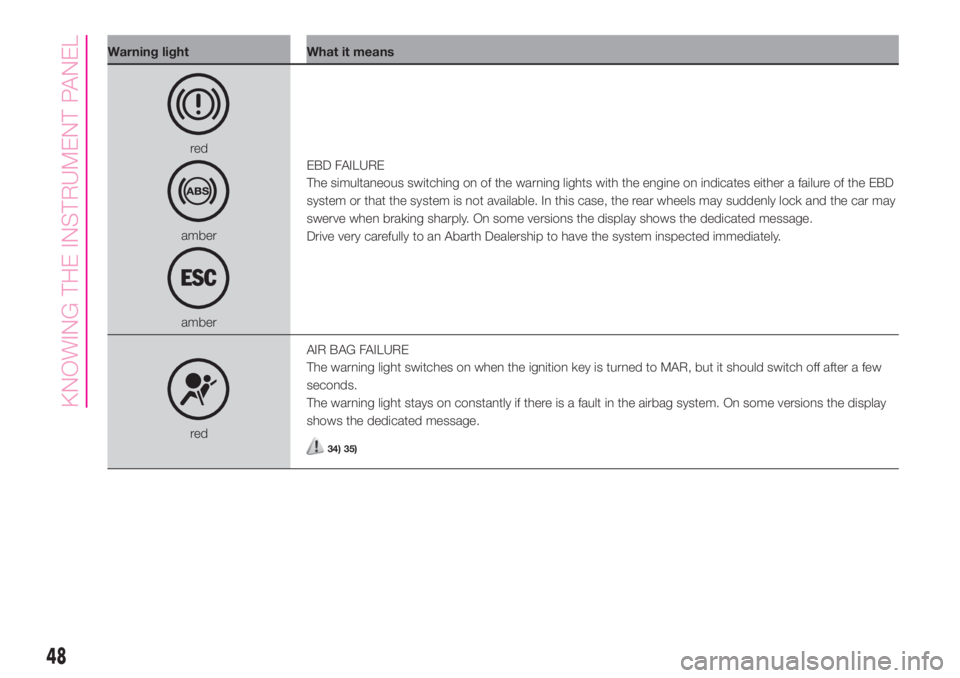
Warning light What it means
red
amber
amberEBD FAILURE
The simultaneous switching on of the warning lights with the engine on indicates either a failure of the EBD
system or that the system is not available. In this case, the rear wheels may suddenly lock and the car may
swerve when braking sharply. On some versions the display shows the dedicated message.
Drive very carefully to an Abarth Dealership to have the system inspected immediately.
redAIR BAG FAILURE
The warning light switches on when the ignition key is turned to MAR, but it should switch off after a few
seconds.
The warning light stays on constantly if there is a fault in the airbag system. On some versions the display
shows the dedicated message.34) 35)
48
KNOWING THE INSTRUMENT PANEL
Page 63 of 196
ACTIVE SAFETY
SYSTEMS
The car has the following active safety
systems:
ABS (Anti-lock Braking System);
EBD (Electronic Brake force
Distribution);
DTC (Drag Torque Control);
ESC (Electronic Stability Control);
HH (Hill Holder);
ASR (Antislip Regulation);
PBA (Panic Brake Assist);
TTC (Torque Transfer Control)
For the operation of the systems, see
the following description.
ABS (Anti-lock Braking
System)
This system, which is an integral part of
the braking system, prevents one or
more wheels from locking and slipping
on all road surface conditions,
irrespective of the intensity of the
braking action, ensuring that the car
can be controlled even during
emergency braking thus optimising
stopping distances.
The system intervenes during braking
when the wheels are about to lock,
typically in emergency braking or
low-grip conditions, when locking may
be more frequent.The system also improves control and
stability of the car when braking on a
surface where the grip of the left and
right wheels varies, or on corners.
The Electronic Braking Force
Distribution (EBD) system completes
the system allowing the brake force to
be distributed between the front and
rear wheels.
System intervention
A slight pulsing of the brake pedal and
noise indicates the intervention of the
ABS: this is completely normal when
the system intervenes.
40) 41) 42) 43) 44) 45) 46) 47) 48)
DTC (Drag Torque
Control) SYSTEM
The system prevents the drive wheels
from possibly locking, which could
happen, for example, if the accelerator
pedal is released suddenly or in the
case of a sudden downshifting in
conditions of poor grip. In these
conditions, the engine braking effect
could cause the drive wheels to slip,
resulting in a loss of car stability. In
these situations, the DTC system
intervenes, restoring torque to the
engine in order to conserve vehicle
stability and increase vehicle safety.
ESC (Electronic Stability
Control) SYSTEM
The ESC system improves the
directional control and stability of the
car in various driving conditions. The
ESC system corrects the car’s
understeer and oversteer, distributing
the brake force on the wheels
appropriately. The torque supplied by
the engine can also be reduced in order
to maintain control of the car. The
ESC system uses sensors installed on
the vehicle to determine the trajectory
that the driver intends to follow and
compares it with the vehicle’s effective
trajectory. When the real trajectory
deviates from the desired trajectory, the
ESC system intervenes to counter the
understeer or oversteer of the car.
Oversteer: occurs when the car is
turning more than it should according
to the angle of the steering wheel.
Understeer: occurs when the car is
turning less than it should according to
the angle of the steering wheel.
System intervention
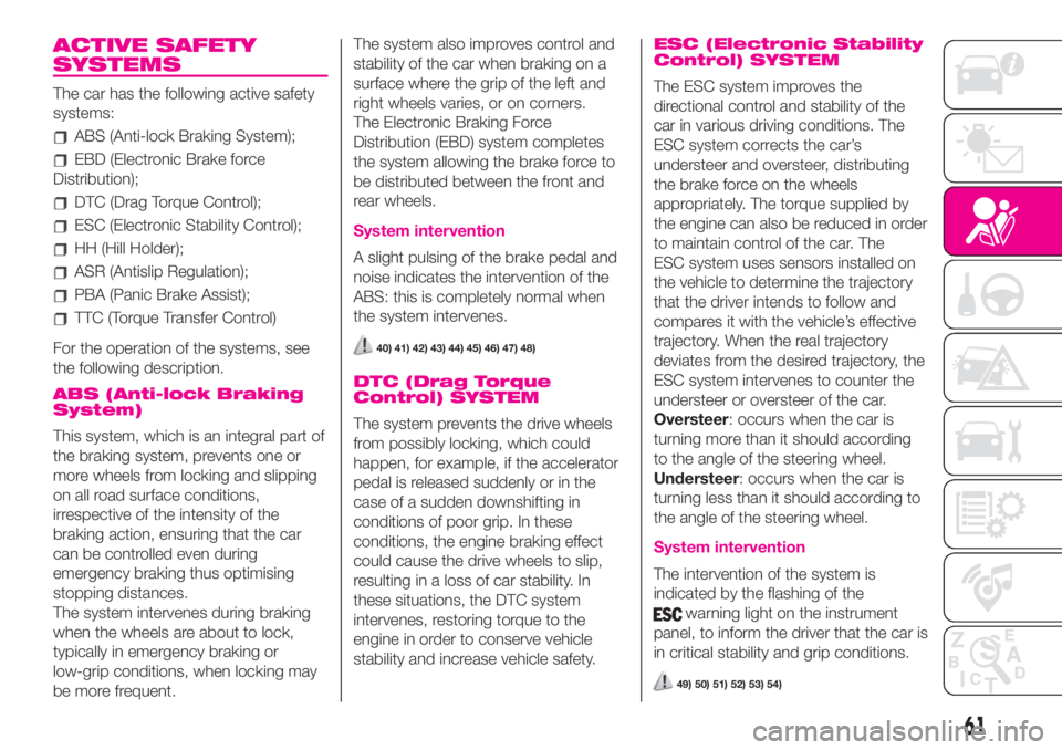
The intervention of the system is
indicated by the flashing of the
warning light on the instrument
panel, to inform the driver that the car is
in critical stability and grip conditions.
49) 50) 51) 52) 53) 54)
61