set Abarth 500 2019 Owner handbook (in English)
[x] Cancel search | Manufacturer: ABARTH, Model Year: 2019, Model line: 500, Model: Abarth 500 2019Pages: 196, PDF Size: 3.53 MB
Page 4 of 196
ESSENTIAL INFORMATION!
REFUELLING
Only refuel with unleaded petrol with octane rating (RON) not less than 95, in compliance with the European specification EN 228. The use of
other products or mixtures may damage the engine beyond repair and consequently invalidate the warranty, due to the damage caused.
STARTING THE ENGINE
Version with manual gearbox: make sure that the handbrake is engaged; set the gear lever to neutral; fully depress the clutch pedal
without pressing the accelerator, then turn the ignition key to AVV and release it as soon as the engine has started.
Versions with robotised sequential gearbox: make sure that the handbrake is engaged and that the gear lever is in P (Parking) or N
(Neutral), fully depress the brake pedal, then turn the ignition key to AVV and release it as soon as the engine is started.
PARKING ON FLAMMABLE MATERIAL
The catalytic converter develops high temperatures during operation. Do not park the car on grass, dry leaves, pine needles or other
flammable material: fire hazard.
RESPECTING THE ENVIRONMENT
The vehicle is fitted with a system that carries out a continuous diagnosis of the emission-related components in order to help protect the
environment.
ELECTRICAL ACCESSORIES
If, after buying the car, you decide to install electrical accessories (with the risk of gradually draining the battery), contact an Abarth
Dealership. They will calculate the overall electrical consumption and check that the car’s electrical system can support the required load.
CODE Card(where provided)
Keep it in a safe place, not in the car. We recommend that you always carry the electronic code provided on the CODE Card with you, in
case you need to perform an emergency start.
SCHEDULED SERVICING
Correct maintenance of the car is essential for ensuring that it maintains its performance and its safety features, its environmental friendliness
and low running costs for a long time to come.
THE OWNER HANDBOOK CONTAINS
... important information, advice and warnings for correct use, driving safety and maintenance of your car over time. Special attention must
be paid to the symbols provided
(safety of persons)(environmental protection)(car integrity).
Page 13 of 196
KEYS
1)
1)
MECHANICAL KEY
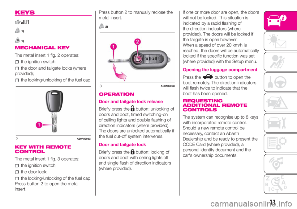
The metal insert 1 fig. 2 operates:
the ignition switch;
the door and tailgate locks (where
provided);
the locking/unlocking of the fuel cap.
KEY WITH REMOTE
CONTROL
The metal insert 1 fig. 3 operates:
the ignition switch;
the door lock;
the locking/unlocking of the fuel cap.
Press button 2 to open the metal
insert.Press button 2 to manually reclose the
metal insert.
2)
OPERATION
Door and tailgate lock release
Briefly press thebutton: unlocking of
doors and boot, timed switching-on
of ceiling lights and double flashing of
direction indicators (where provided).
The doors are unlocked automatically if
the fuel cut-off system intervenes.
Door and tailgate lock
Briefly press thebutton: locking of
doors and boot with ceiling lights off
and single flash of direction indicators
(where provided).If one or more door are open, the doors
will not be locked. This situation is
indicated by a rapid flashing of
the direction indicators (where
provided). The doors will be locked if
the tailgate is open however.
When a speed of over 20 km/h is
reached, the doors will be automatically
locked if the specific function was set
(where provided) with the Setup menu.
Opening the luggage compartment
Press thebutton to open the
boot remotely. The direction indicators
will flash twice to indicate that the
boot has been opened.
REQUESTING
ADDITIONAL REMOTE
CONTROLS
The system can recognise up to 8 keys
with incorporated remote control.
Should a new remote control be
necessary, contact an Abarth
Dealership and be ready to present the
CODE Card (where provided), a
personal identity document and the
car's ownership documents.
2AB0A0303C
3AB0A0006C
11
Page 19 of 196
REAR SEATS
Extending the luggage
compartment
11)
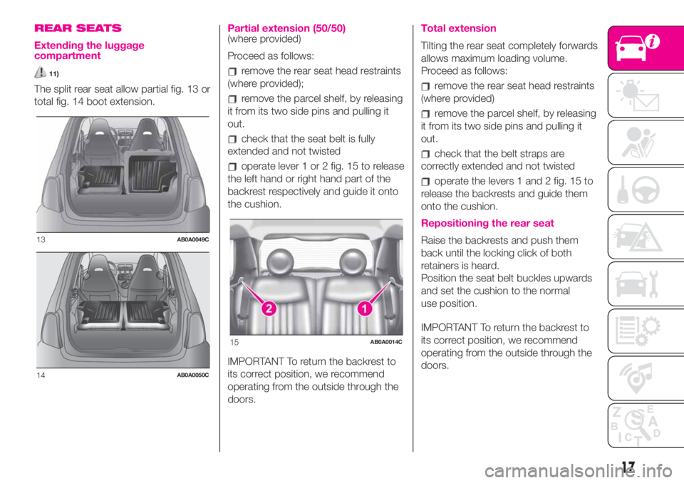
The split rear seat allow partial fig. 13 or
total fig. 14 boot extension.
Partial extension (50/50)(where provided)
Proceed as follows:
remove the rear seat head restraints
(where provided);
remove the parcel shelf, by releasing
it from its two side pins and pulling it
out.
check that the seat belt is fully
extended and not twisted
operate lever 1 or 2 fig. 15 to release
the left hand or right hand part of the
backrest respectively and guide it onto
the cushion.
IMPORTANT To return the backrest to
its correct position, we recommend
operating from the outside through the
doors.
Total extension
Tilting the rear seat completely forwards
allows maximum loading volume.
Proceed as follows:
remove the rear seat head restraints
(where provided)
remove the parcel shelf, by releasing
it from its two side pins and pulling it
out.
check that the belt straps are
correctly extended and not twisted
operate the levers 1 and 2 fig. 15 to
release the backrests and guide them
onto the cushion.
Repositioning the rear seat
Raise the backrests and push them
back until the locking click of both
retainers is heard.
Position the seat belt buckles upwards
and set the cushion to the normal
use position.
IMPORTANT To return the backrest to
its correct position, we recommend
operating from the outside through the
doors.13AB0A0049C
14AB0A0050C
15AB0A0014C
17
Page 20 of 196
IMPORTANT When returning the
backrest to its normal position, make
sure that it is correctly fastened and
that you hear the lock click. Make sure
the backrest is properly secured at both
sides to prevent it moving forward in
the event of sharp braking that may
cause injuries to passengers
WARNING
8)All adjustments must be made with the
car stationary.
9)If a side bag is fitted, it is dangerous to
use seat covers not available from
Lineaccessori Abarth.
10)Once you have released the
adjustment lever, always check that the
seat is locked on the guides by trying
to move it back and forth. Failure to lock
the seat in place could result in the seat
moving suddenly and the driver losing
control of the car.
11)Make sure the backrests are properly
secured at both sides to prevent them from
moving forward, in the event of sharp
braking, and hurting the passengers.
WARNING
2)The fabric upholstery of the seats has
been designed to withstand long-term
wear deriving from normal use of the car.
Some precautions are however required.
Avoid prolonged and/or excessive rubbing
against clothing accessories such as
metal buckles and Velcro strips which, by
applying a high pressure on the fabric in
a small area, could cause it to break,
thereby damaging the upholstery.
3)Before tilting the backrest, remove any
objects on the seat cushion.
HEADRESTS
REAR(where provided)
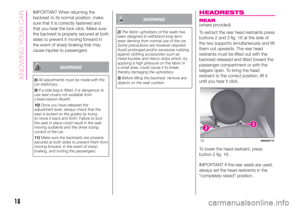
To extract the rear head restraints press
buttons 2 and 3 fig. 16 at the side of
the two supports simultaneously and lift
them out upwards. The rear head
restraints must be lifted out with the
backrest released and tilted toward the
passenger compartment or with the
tailgate open. To bring the head
restraint to the correct position, lift it
until you hear it click.
To lower the head restraint, press
button 2 fig. 16.
IMPORTANT If the rear seats are used,
always set the head restraints in the
"completely raised" position.
16AB0A0017C
18
KNOWING YOUR CAR
Page 22 of 196
There is an ON/OFF button on the
lower part of the mirror for
activating/deactivating the
electrochromic function. When the
function is active, a LED on the mirror is
active. When reverse is engaged, the
mirror is automatically set for daytime
use.
DOOR MIRRORS
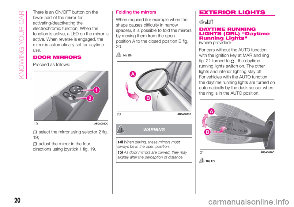
Proceed as follows:
select the mirror using selector 2 fig.
19;
adjust the mirror in the four
directions using joystick 1 fig. 19.
Folding the mirrors
When required (for example when the
shape causes difficulty in narrow
spaces), it is possible to fold the mirrors
by moving them from the open
position A to the closed position B fig.
20.
14) 15)
WARNING
14)When driving, these mirrors must
always be in the open position.
15)As door mirrors are curved, they may
slightly alter the perception of distance.
EXTERIOR LIGHTS
DAYTIME RUNNING
LIGHTS (DRL) "Daytime
Running Lights"
(where provided)
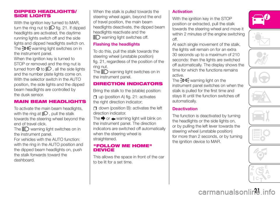
For cars without the AUTO function:
with the ignition key at MAR and ring
fig. 21 turned to
, the daytime
running lights switch on. The other
lights and interior lighting stay off.
For vehicles with the AUTO function:
the daytime running lights are turned on
automatically by the dusk sensor when
the ring is in the AUTO position.
16) 17)
19AB0A0020C
20AB0A0021C
21AB0A0026C
20
KNOWING YOUR CAR
Page 23 of 196
DIPPED HEADLIGHTS/
SIDE LIGHTS
With the ignition key turned to MAR,
turn the ring nut to
fig. 21. If dipped
headlights are activated, the daytime
running lights switch off and the side
lights and dipped headlights switch on.
The
warning light switches on in
the instrument panel.
When the ignition key is turned to
STOP or removed and the ring nut is
turned fromOto
, all the side lights
and the number plate lights come on.
With the selector switch in the AUTO
position, the side lights and the dipped
beam headlights are controlled by
the dusk sensor.
MAIN BEAM HEADLIGHTS
To activate the main beam headlights,
with the ring at
, pull the stalk
towards the steering wheel beyond the
end of travel click.
The
warning light switches on in
the instrument panel.
For vehicles with the AUTO function:
with the ring in the AUTO position and
the dipped beam headlights on, push
the stalk forwards toward the
dashboard.When the stalk is pulled towards the
steering wheel again, beyond the end
of travel position, the main beam
headlights deactivate, the dipped beam
headlights reactivate and the
warning light switches off.
Flashing the headlights
To do this, pull the stalk towards the
steering wheel (unstable position)
fig. 21, regardless of the position of the
ring nut.
The
warning light switches on in
the instrument panel.
DIRECTION INDICATORS
Bring the stalk to the (stable) position:
up (position A) fig. 21: activates
the right direction indicator;
down (position B): activates the left
direction indicator.
The
orwarning light will blink on
the instrument panel. The direction
indicators are switched off automatically
when the steering wheel is
straightened.
"FOLLOW ME HOME"
DEVICE
This allows the space in front of the car
to be lit for a set time.
Activation
With the ignition key in the STOP
position or extracted, pull the stalk
towards the steering wheel and move it
within 2 minutes of the engine switching
off.
At each single movement of the stalk,
the lights will remain on for an extra
30 seconds up to a maximum of 210
seconds: then the lights are switched
off automatically. The display shows the
time for which the functions remains
active.
The
warning light on the
instrument panel switches on when the
stalk is pulled for the first time and
stays lit until the function switches off
automatically.
Deactivation
The function is deactivated by turning
the headlights or the side lights on,
or by pulling the left lever towards the
steering wheel (unstable position)
for more than 2 seconds, or by turning
the ignition device to MAR.
21
Page 25 of 196
WARNING
16)The daytime running lights are an
alternative to the dipped beam headlights
for driving during the daytime in countries
where it is compulsory to have lights on
during the day; where it is not compulsory,
the use of daytime running lights is
permitted.
17)Daytime running lights cannot replace
dipped beam headlights when driving at
night or through tunnels. The use of
daytime running lights is governed by the
highway code of the country in which
you are driving. Comply with legal
requirements.
ROOF LIGHTS
FRONT CEILING LIGHT
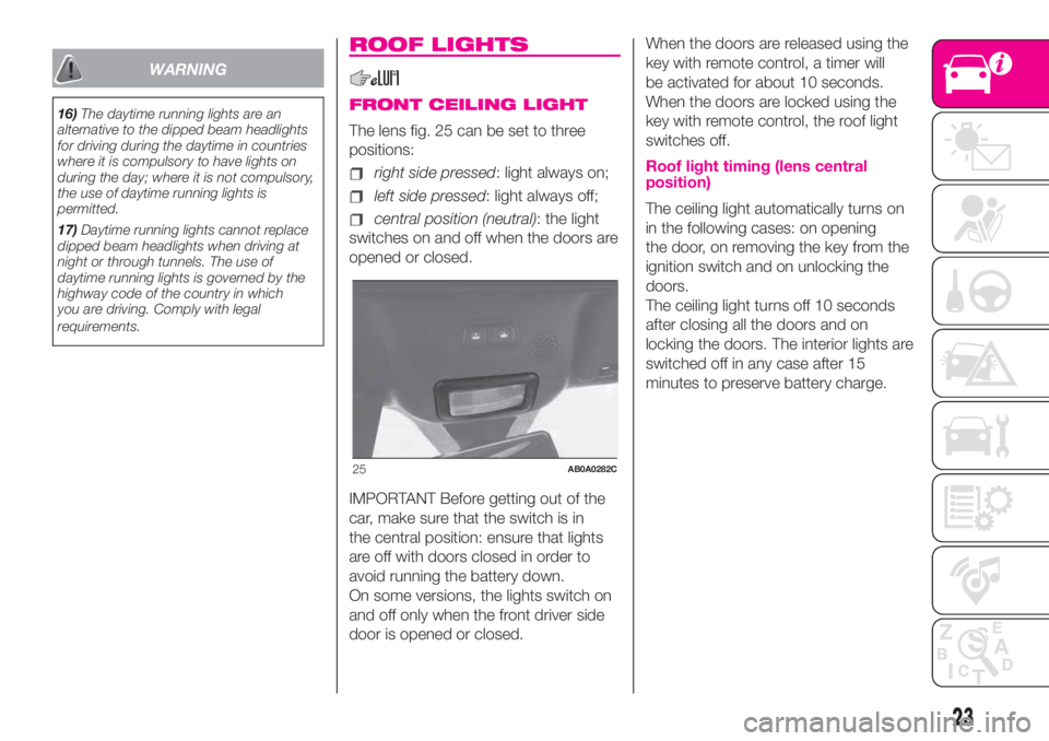
The lens fig. 25 can be set to three
positions:
right side pressed: light always on;
left side pressed: light always off;
central position (neutral): the light
switches on and off when the doors are
opened or closed.
IMPORTANT Before getting out of the
car, make sure that the switch is in
the central position: ensure that lights
are off with doors closed in order to
avoid running the battery down.
On some versions, the lights switch on
and off only when the front driver side
door is opened or closed.When the doors are released using the
key with remote control, a timer will
be activated for about 10 seconds.
When the doors are locked using the
key with remote control, the roof light
switches off.
Roof light timing (lens central
position)
The ceiling light automatically turns on
in the following cases: on opening
the door, on removing the key from the
ignition switch and on unlocking the
doors.
The ceiling light turns off 10 seconds
after closing all the doors and on
locking the doors. The interior lights are
switched off in any case after 15
minutes to preserve battery charge.
25AB0A0282C
23
Page 32 of 196
3)
Depending on the temperature set by
the user, the automatic climate control
system automatically regulates the
temperature, flow and distribution of the
passenger compartment air, as well as
the recirculation function. These
settings can be changed by the user,
putting the climate control system
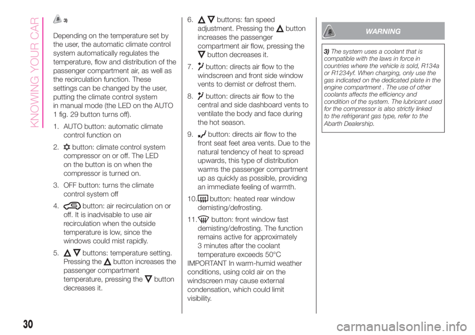
in manual mode (the LED on the AUTO
1 fig. 29 button turns off).
1. AUTO button: automatic climate
control function on
2.
button: climate control system
compressor on or off. The LED
on the button is on when the
compressor is turned on.
3. OFF button: turns the climate
control system off
4.
button: air recirculation on or
off. It is inadvisable to use air
recirculation when the outside
temperature is low, since the
windows could mist rapidly.
5.
buttons: temperature setting.
Pressing the
button increases the
passenger compartment
temperature, pressing the
button
decreases it.6.
buttons: fan speed
adjustment. Pressing the
button
increases the passenger
compartment air flow, pressing the
button decreases it.
7.
button: directs air flow to the
windscreen and front side window
vents to demist or defrost them.
8.
button: directs air flow to the
central and side dashboard vents to
ventilate the body and face during
the hot season.
9.
button: directs air flow to the
front seat feet area vents. Due to the
natural tendency of heat to spread
upwards, this type of distribution
warms the passenger compartment
up as quickly as possible, providing
an immediate feeling of warmth.
10.
button: heated rear window
demisting/defrosting.
11.
button: front window fast
demisting/defrosting. The function
remains active for approximately
3 minutes after the coolant
temperature exceeds 50°C
IMPORTANT In warm-humid weather
conditions, using cold air on the
windscreen may cause external
condensation, which could limit
visibility.
WARNING
3)The system uses a coolant that is
compatible with the laws in force in
countries where the vehicle is sold, R134a
or R1234yf. When charging, only use the
gas indicated on the dedicated plate in the
engine compartment . The use of other
coolants affects the efficiency and
condition of the system. The lubricant used
for the compressor is also strictly linked
to the refrigerant gas type, refer to the
Abarth Dealership.
30
KNOWING YOUR CAR
Page 45 of 196
GEAR SHIFT INDICATOR
The GSI (Gear Shift Indicator) system
advises the driver to change gear
through a special indication on the
display.
Through the GSI, the driver is informed
that the gear change will allow a
reduction in fuel consumption.
When the SHIFT (SHIFT UP) icon
is
shown on the display, the GSI is
advising the driver to engage a higher
gear, while the SHIFT (SHIFT DOWN)
icon
advises the driver to engage
a lower gear.
The indication on the instrument panel
remains until the driver shifts gear or the
driving conditions return to a situation
where gearshifting is not required to
improve consumption.
ANALOGUE PRESSURE
GAUGE
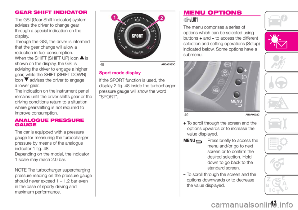
The car is equipped with a pressure
gauge for measuring the turbocharger
pressure by means of the analogue
indicator 1 fig. 48.
Depending on the model, the indicator
1 scale may reach 2.0 bar.
NOTE The turbocharger supercharging
pressure reading on the pressure gauge
should never exceed 1 – 1.2 bar even
in the case of sporty driving and
maximum performance.
Sport mode display
If the SPORT function is used, the
display 2 fig. 48 inside the turbocharger
pressure gauge will show the word
“SPORT”.
MENU OPTIONS
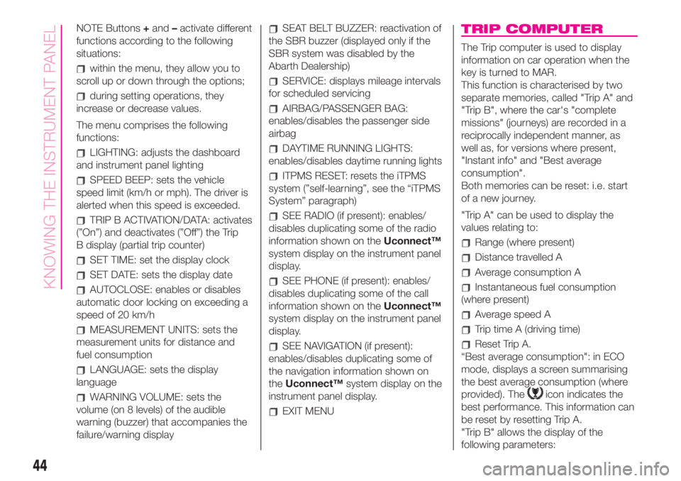
The menu comprises a series of
options which can be selected using
buttons+and–to access the different
selection and setting operations (Setup)
indicated below. Some options have a
submenu.
+To scroll through the screen and the
options upwards or to increase the
value displayed.
MENUPress briefly to access the
menu and/or go to next
screen or to confirm the
desired selection. Hold
down to go back to the
standard screen.
–To scroll through the screen and the
options downwards or to decrease
the value displayed.
48AB0A0333C
49AB0A0002C
43
Page 46 of 196
NOTE Buttons+and–activate different
functions according to the following
situations:
within the menu, they allow you to
scroll up or down through the options;
during setting operations, they
increase or decrease values.
The menu comprises the following
functions:
LIGHTING: adjusts the dashboard
and instrument panel lighting
SPEED BEEP: sets the vehicle
speed limit (km/h or mph). The driver is
alerted when this speed is exceeded.
TRIP B ACTIVATION/DATA: activates
(”On”) and deactivates (”Off”) the Trip
B display (partial trip counter)
SET TIME: set the display clock
SET DATE: sets the display date
AUTOCLOSE: enables or disables
automatic door locking on exceeding a
speed of 20 km/h
MEASUREMENT UNITS: sets the
measurement units for distance and
fuel consumption
LANGUAGE: sets the display
language
WARNING VOLUME: sets the
volume (on 8 levels) of the audible
warning (buzzer) that accompanies the
failure/warning display
SEAT BELT BUZZER: reactivation of
the SBR buzzer (displayed only if the
SBR system was disabled by the
Abarth Dealership)
SERVICE: displays mileage intervals
for scheduled servicing
AIRBAG/PASSENGER BAG:
enables/disables the passenger side
airbag
DAYTIME RUNNING LIGHTS:
enables/disables daytime running lights
ITPMS RESET: resets the iTPMS
system (”self-learning”, see the “iTPMS
System” paragraph)
SEE RADIO (if present): enables/
disables duplicating some of the radio
information shown on theUconnect™
system display on the instrument panel
display.
SEE PHONE (if present): enables/
disables duplicating some of the call
information shown on theUconnect™
system display on the instrument panel
display.
SEE NAVIGATION (if present):
enables/disables duplicating some of
the navigation information shown on
theUconnect™system display on the
instrument panel display.
EXIT MENU
TRIP COMPUTER
The Trip computer is used to display
information on car operation when the
key is turned to MAR.
This function is characterised by two
separate memories, called "Trip A" and
"Trip B", where the car's "complete
missions" (journeys) are recorded in a
reciprocally independent manner, as
well as, for versions where present,
"Instant info" and "Best average
consumption".
Both memories can be reset: i.e. start
of a new journey.
"Trip A" can be used to display the
values relating to:
Range (where present)
Distance travelled A
Average consumption A
Instantaneous fuel consumption
(where present)
Average speed A
Trip time A (driving time)
Reset Trip A.
“Best average consumption": in ECO
mode, displays a screen summarising
the best average consumption (where
provided). The
icon indicates the
best performance. This information can
be reset by resetting Trip A.
"Trip B" allows the display of the
following parameters:
44
KNOWING THE INSTRUMENT PANEL