display Abarth Grande Punto 2007 Owner handbook (in English)
[x] Cancel search | Manufacturer: ABARTH, Model Year: 2007, Model line: Grande Punto, Model: Abarth Grande Punto 2007Pages: 207, PDF Size: 3.01 MB
Page 45 of 207
43
SAFETY
DEVICES
CORRECT USE
OF THE CAR
WARNING
LIGHTS AND
MESSAGES
IIN AN
EMERGENCY
CAR
MAINTENANCE
TECHNICAL
SPECIFICATIONS
INDEX
DASHBOARD
AND CONTROLS
˙Splitting of the air flow
Obetween the vents to the lower part
of the passenger compartment
(warmest air) and the dashboard cen-
tre and side outlets (coolest air). This
air flow distribution is particularly use-
ful in spring and autumn when the sun
is shining.
NSplitting of the air flow between
Owindscreen and front side window
demisting/defrosting vents and the
lower part of the passenger compart-
ment. This type of air distribution al-
lows satisfactory heating of the pas-
senger compartment while preventing
possible misting of the windows.
NSplitting of the air flow between
˙windscreen demisting/defrosting vents
and central and side dashboard vents.
This type of air distribution allows sat-
isfactory ventilation when the sun is
shining.
NSplitting of the air flow between
˙all car vents.
O
During FULL AUTOoperation the sys-
tem will control automatically air distrib-
ution choosing the most appropriate ac-
cording to climate conditions. When in
FULL AUTOdistribution leds are off.The type of air distribution, when select-
ed by hand, is shown by lighting up of the
relevant led on the selected button. In the
combined function, pressing a button will
activate the relevant function whereas,
pressing a button relevant to an already
operating function will turn off this func-
tion and the relevant button led. To re-
store automatic air distribution control af-
ter a manual selection, press button AU-
TO.
When the driver selects air distribution to
the windscreen, also the air distribution
on passenger side will be distributed to the
windscreen. The passenger can however
select the required air distribution by
pressing the relevant buttons.
Fan speed adjusting buttons L
Press button pto increase or to decrease
the fan speed and therefore the amount
of air admitted into the passenger com-
partment, although keeping the required
temperature set.The fan speed is shown by the lit bars on
the display:
❒max fan speed = all bars lit;
❒min fan speed = one bar lit.
The fan can be cut off only if the climate
control compressor has been switched off
pressing button B.
IMPORTANT To restore automatic fan
speed control after a manual adjustment,
press button AUTO.
AUTO buttons
(automatic operation) H-N
Pressing the AUTObutton (on driver
and/or front passenger side) the system au-
tomatically adjusts the amount and distri-
bution of the air admitted to the passenger
compartment, cancelling all the previous
manual adjustments. This condition is in-
dicated by the message FULL AUTOon
the front system display. Manual operation
of at least one automatic function (air re-
circulation, air distribution, fan speed or cli-
mate control compressor off) will cause
FULLmessage going off the display. This
means that automatic control is not com-
plete (except temperature control which is
always automatic).
Page 46 of 207
44
SAFETY
DEVICES
CORRECT USE
OF THE CAR
WARNING
LIGHTS AND
MESSAGES
IN AN
EMERGENCY
CAR
MAINTENANCE
TECHNICAL
SPECIFICATIONS
INDEX
DASHBOARD
AND CONTROLS
IMPORTANT Should the system (after
manual settings) be no longer able to guar-
antee the required temperature set in the
passenger compartment, the set tempera-
ture value will start flashing to indicate this
condition, after one minute the AUTO
message will turn off.
To restore system automatic control at
any time, after one or more manual ad-
justments, press button AUTO.
MONO button (to align set
temperatures and air
distribution) A
Pressing button MONOautomatically
aligns the temperature on the passenger
side with that on the driver side, it is
therefore possible to set the same tem-
perature and air distribution between the
two zones by turning the knob on driver
side. This function is provided to simplify
temperature adjustment of the whole pas-
senger compartment when only the dri-
ver is onboard. Separate operation of set
temperature and air distribution is re-
stored by turning knob H(to set tem-
perature on front passenger side) or by
pressing again button MONOwhen the
button led is on.Air recirculation on/off button C
Air recirculation works according to the
following operating logics:
❒automatic switching on, by pressing one
of the AUTObuttons and indicated by
the turning on of the AUTOicon on the
display near the car outline;
❒forced switching on (inside air recircu-
lation always on), indicated by the turn-
ing off of the button led Cand symbol
íon the display;
❒forced switching off (air recirculation
always off with air inlet from the out-
side), indicated by the turning off of the
button led and symbol
êon the dis-
play. Forced recirculation on/off can be
selected through button C.
IMPORTANT The inside air recirculation
system makes it possible to reach the re-
quired heating or cooling conditions faster.
It is however inadvisable to use it on
rainy/cold days as it would considerably
increase the possibility of the windows
misting inside, especially if the climate con-
trol system is off.When outside temperature is cold, recir-
culation is forced to off (outside air inlet)
to prevent window misting up.
In automatic operation inside air recircu-
lation will be controlled automatically by
the system according to outside environ-
mental conditions.
When setting manual recirculation, word-
ings FULLand AUTOdisappear from
the display.
It is inadvisable to use air re-
circulation on rainy/cold
days as it would considerably increase
the possibility of windows misting up
inside.
WARNING
Page 47 of 207

45
SAFETY
DEVICES
CORRECT USE
OF THE CAR
WARNING
LIGHTS AND
MESSAGES
IIN AN
EMERGENCY
CAR
MAINTENANCE
TECHNICAL
SPECIFICATIONS
INDEX
DASHBOARD
AND CONTROLS
Climate control compressor on/off
button B
Pressing button
√when the button led
is on, will deactivate compressor and turn
the button led off. Pressing the button
when the led is off will activate compres-
sor and turn the button led on. When
turning the compressor off, the system will
deactivate air recirculation to prevent win-
dow misting up.
In this event, although the system is able
to keep the required temperature, the
wording FULLwill disappear from the
display. If the system is no longer able to
keep the required temperature, temper-
ature value will flash and the wording
AUTOwill disappear from the display.
IMPORTANT With the climate control
compressor off, it is not possible to admit
air to the passenger compartment with a
temperature below the outside tempera-
ture; moreover, under certain environ-
mental conditions, windows could mist up
fastly since air is not dehumidified.
The switching off of the climate control
compressor remains in storage even when
the engine has been stopped.
To restore automatic control for switch-
ing on the climate control compressor,
press again button
√or press button AU-
TO.
With climate control compressor off if
outside temperature is higher than the set
one the system will not be able to keep
the required condition, the temperaturevalue will then start to flash on the display
for a few seconds and wording AUTO
will then go off.
With climate control compressor off, the
fan speed can be set to zero manually.
With compressor on and engine running,
the fan speed cannot be lower that one
bar on the display.
Fast window demisting/defrosting
button F
Press this button: the climate control sys-
tem will automatically switch on all the
functions required for fast windscreen and
front side window demisting/defrosting,
that is:
❒ switches on climate control compres-
sor when climatic conditions are suit-
able;
❒air recirculation off;
❒maximum air temperature HIon both
areas;
❒activates proper fan speed according to
engine coolant temperature to limit the
flow into the passenger compartment of
air not warm enough to demist the win-
dows;
❒ directs air flow to windscreen and front
side windows vents;
❒turns heated rear window on.IMPORTANT Fast demisting/defrosting
function stays on for about 3 minutes,
since engine coolant temperature reach-
es the proper temperature.
When the max. demisting/defrosting func-
tion is on, the button led and the heated
rear window button led are on.
FULL AUTOwording on the display is
off.
When the max. demisting/defrosting func-
tion is on, the only manual operations pos-
sible are manual adjustment of the fan
speed and switching heated rear window
off. Pressing the max. demisting/defrosting
button or the air recirculation buttons or
compressor off button or the AUTO
button, the system switches off the max.
demisting/defrosting function and restores
the operating conditions of the system pri-
or to turning it on.
Page 48 of 207

46
SAFETY
DEVICES
CORRECT USE
OF THE CAR
WARNING
LIGHTS AND
MESSAGES
IN AN
EMERGENCY
CAR
MAINTENANCE
TECHNICAL
SPECIFICATIONS
INDEX
DASHBOARD
AND CONTROLS
Heated rear window and door
mirror demisting/defrosting button
(for versions/markets,
where provided) G
Press this button to activate heated rear
window demisting/defrosting.
When this function is on, the button led
is on.
This function is timed and switches off au-
tomatically after about 20 minutes or by
pressing again the button or by turning the
engine off. It will not be switched on au-
tomatically when restarting the engine.
IMPORTANT Do not apply stickers on the
inside of the rear window over the heat-
ing filaments to avoid damage that might
cause it to stop working properly.
Switching the climate control
system off (OFF) E
Press button Eto turn the system off.
When turned off the system conditions
are the following:
❒set temperature displays off;
❒air recirculation is on;
❒conditioner compressor off;
❒fan off.
Heated rear window can be turned on or
off also when the system is off.
IMPORTANT The system will store the
temperatures set before turning off and
will resume them when pressing any but-
ton (except heated rear window); if the
function corresponding to the button
pressed is off it will be turned on; if on it
will be kept active.
Press AUTOto turn the system in au-
tomatic mode.ADDITIONAL HEATER
(for versions/markets,
where provided)
This device shall be used to speed up pas-
senger compartment warming when it is
very cold.
The additional heater turns off automati-
cally after reaching the required comfort
conditions.
Automatic two-zone climate
control system
The additional heater will switch on au-
tomatically after turning the ignition key
to ON.
Manual Heater and Climate
control system
The additional heater will switch on au-
tomatically by turning knob Ato the last
red sector and turning the fan on (knob
B) to the first speed at least.
IMPORTANT Heater works only with
low outside temperature and engine
coolant temperature.
IMPORTANT Heater will not turn on if
the battery voltage is not sufficient.
Page 50 of 207
48
SAFETY
DEVICES
CORRECT USE
OF THE CAR
WARNING
LIGHTS AND
MESSAGES
IN AN
EMERGENCY
CAR
MAINTENANCE
TECHNICAL
SPECIFICATIONS
INDEX
DASHBOARD
AND CONTROLS
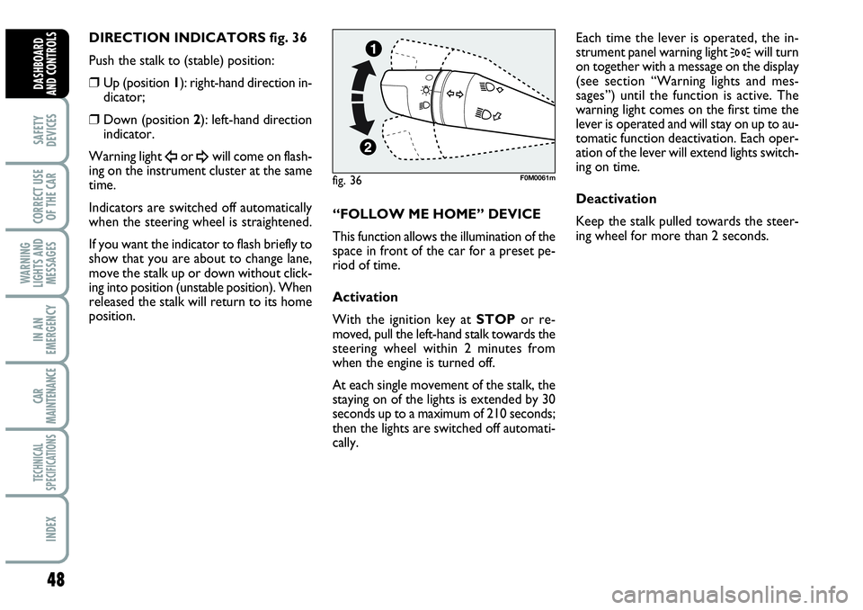
DIRECTION INDICATORS fig. 36
Push the stalk to (stable) position:
❒Up (position 1): right-hand direction in-
dicator;
❒Down (position 2): left-hand direction
indicator.
Warning light
Îor ¥will come on flash-
ing on the instrument cluster at the same
time.
Indicators are switched off automatically
when the steering wheel is straightened.
If you want the indicator to flash briefly to
show that you are about to change lane,
move the stalk up or down without click-
ing into position (unstable position). When
released the stalk will return to its home
position.“FOLLOW ME HOME” DEVICE
This function allows the illumination of the
space in front of the car for a preset pe-
riod of time.
Activation
With the ignition key at STOPor re-
moved, pull the left-hand stalk towards the
steering wheel within 2 minutes from
when the engine is turned off.
At each single movement of the stalk, the
staying on of the lights is extended by 30
seconds up to a maximum of 210 seconds;
then the lights are switched off automati-
cally. Each time the lever is operated, the in-
strument panel warning light
3will turn
on together with a message on the display
(see section “Warning lights and mes-
sages”) until the function is active. The
warning light comes on the first time the
lever is operated and will stay on up to au-
tomatic function deactivation. Each oper-
ation of the lever will extend lights switch-
ing on time.
Deactivation
Keep the stalk pulled towards the steer-
ing wheel for more than 2 seconds.
fig. 36F0M0061m
Page 59 of 207
57
SAFETY
DEVICES
CORRECT USE
OF THE CAR
WARNING
LIGHTS AND
MESSAGES
IIN AN
EMERGENCY
CAR
MAINTENANCE
TECHNICAL
SPECIFICATIONS
INDEX
DASHBOARD
AND CONTROLS
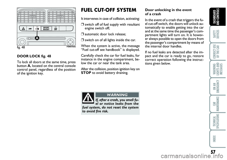
DOOR LOCK fig. 48
To lock all doors at the same time, press
button A, located on the central console
control panel, regardless of the position
of the ignition key.
FUEL CUT-OFF SYSTEM
It intervenes in case of collision, activating:
❒switch off of fuel supply with resultant
engine switch off;
❒automatic door lock release;
❒switch on of all lights inside the car.
When the system is active, the message
“Fuel cut-off see handbook” is displayed.
Carefully check the car for fuel leaks, for
instance in the engine compartment, be-
low the car or near the tank area.
After the collision, position ignition key on
STOPto avoid battery draining.
fig. 48F0M076Ab
Door unlocking in the event
of a crash
In the event of a crash that triggers the fu-
el cut-off switch, the doors will unlock au-
tomatically to enable getting into the car
and at the same time the passenger’s com-
partment lights will turn on. It is howev-
er always possible to open the doors from
the passenger’s compartment by means of
the internal door handles.
If no fuel leaks are detected after the im-
pact and the car is ready to go, restore
correct operation following the instruc-
tions given below.
If, after a crash, you smell fu-
el or notice leaks from the
fuel system, do not reset the system
to avoid fire risk.
WARNING
Page 67 of 207

65
SAFETY
DEVICES
CORRECT USE
OF THE CAR
WARNING
LIGHTS AND
MESSAGES
IIN AN
EMERGENCY
CAR
MAINTENANCE
TECHNICAL
SPECIFICATIONS
INDEX
DASHBOARD
AND CONTROLS
After locking doors by:
❒remote control;
❒door revolving plug;
it will not be possible to unlock the doors
by pressing button
A-fig. 72set on the
dashboard.
IMPORTANT With central locking system
on, pulling the internal door handle of one
of the front doors will unlock that door.
Pulling the internal door handle of one of the
rear doors will unlock the relevant door.
Lacking power (blown fuse, battery discon-
nected, etc.) it is however possible to lock
the doors manually.
After exceeding 20 km/h speed, doors will
be locked automatically if the set up menu
function has been selected (see paragraph
“Multifunction display” in this section).
Once the dead lock device
has been actuated, doors
cannot be opened from the passen-
ger’s compartment in any way what-
soever. For this reason, make sure
there are no person left inside the car.
If the battery of the key with remote
control is down, the dead lock device
can be deactivated only by fitting the
metal insert of the key in both front
door revolving plugs as described pre-
viously. DEAD LOCK DEVICE
(for versions/markets,
where provided)
This safety device enables to inhibit:
❒door internal handles;
❒locking/unlocking button A-fig. 72;
thus hindering doors opening from inside
the passenger’s compartment in case of at-
tempt to break-into (e.g.: window breaking).
The dead lock device guarantees the best
protection against unwanted access.
Therefore, it should be actuated every
time the car is parked and left unattended.Device activation
The dead lock device is automatically ac-
tivated on every door when pressing twice
briefly the remote control button
Á,
fig. 70.
Device activation is indicated by 3 flashing
of direction indicators and flashing of the
button led A-fig. 72located on the dash-
board.
If one of the doors is not perfectly closed,
the dead lock device will not activate, thus
preventing that a person getting into the car
from the open door remains blocked inside
the passenger’s compartment when she/he
closes the door.
Device deactivation
The device is deactivated automatically on
every door in the following cases:
❒when opening the driver’s door using the
key without remote control;
❒when unlocking doors using the remote
control;
❒turning the ignition key to MAR.
WARNING
Page 76 of 207
74
SAFETY
DEVICES
CORRECT USE
OF THE CAR
WARNING
LIGHTS AND
MESSAGES
IN AN
EMERGENCY
CAR
MAINTENANCE
TECHNICAL
SPECIFICATIONS
INDEX
DASHBOARD
AND CONTROLS
HEADLIGHTS
ADJUSTING THE
HEADLIGHT BEAM
Proper adjustment of the headlight beams
is of vital importance for your safety and
comfort and also for the other road users.
To ensure you and other drivers have the
best visibility conditions when travelling
with the headlights on, the headlights must
be set properly. Contact Abarth Dealer-
ship to have the headlights properly ad-
justed.HEADLIGHT AIMING DEVICE
It works with ignition key at MARand
dipped beams on. When the car is loaded,
it slopes backwards. This means that the
headlight beam rises. In this case, it is nec-
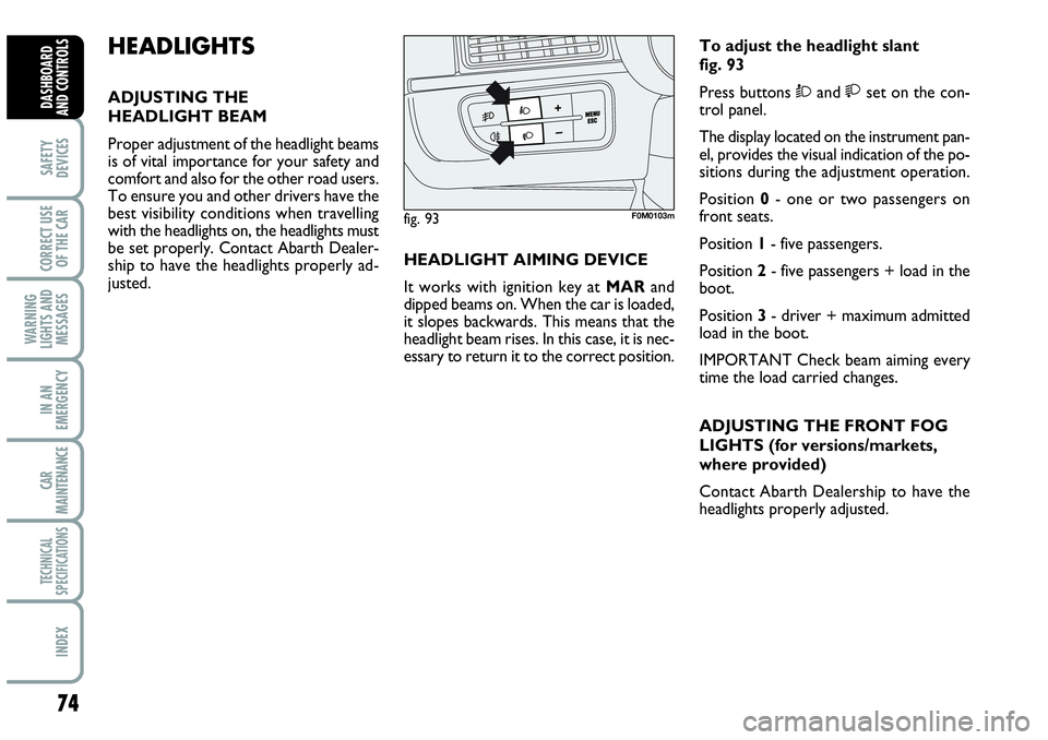
essary to return it to the correct position.To adjust the headlight slant
fig. 93
Press buttons Òand set on the con-
trol panel.
The display located on the instrument pan-
el, provides the visual indication of the po-
sitions during the adjustment operation.
Position 0- one or two passengers on
front seats.
Position 1- five passengers.
Position 2- five passengers + load in the
boot.
Position 3- driver + maximum admitted
load in the boot.
IMPORTANT Check beam aiming every
time the load carried changes.
ADJUSTING THE FRONT FOG
LIGHTS (for versions/markets,
where provided)
Contact Abarth Dealership to have the
headlights properly adjusted.
fig. 93F0M0103m
Page 79 of 207
77
SAFETY
DEVICES
CORRECT USE
OF THE CAR
WARNING
LIGHTS AND
MESSAGES
IIN AN
EMERGENCY
CAR
MAINTENANCE
TECHNICAL
SPECIFICATIONS
INDEX
DASHBOARD
AND CONTROLS
FAILURE INDICATIONS
ABS failure
ABS failure is indicated by the turning on
of warning light
>on the instrument pan-
el together with the dedicated message on
the multifunction display (for versions/
markets, where provided), (see section
“Warning lights and messages”).
In this case the braking system is still effi-
cient, though without the aid of the ABS
system. Drive carefully to the closest
Abarth Dealership to have the system
checked.EBD failure
EBD failure is indicated by the turning on
of warning lights
>and xon the in-
strument panel together with the dedi-
cated message on the multifunction dis-
play (where provided), (see section
“Warning lights and messages”).
In this case with sharp braking the rear
wheels might lock too early, with the pos-
sibility of skidding. Drive extremely care-
fully to the nearest Abarth Dealership to
have the system checked.If warning light xalone
comes on (together with the
message on the multifunction display,
where provided), stop the car imme-
diately and contact the nearest Abarth
Dealership. Fluid leaks from the hy-
draulic system, in fact, can compromise
the braking system, both traditional
systems and systems with ABS.
WARNING
Page 80 of 207
ESP SYSTEM
(Electronic Stability
Program)
The ESP system is an electronic system
controlling the car stability in the event of
tyre grip loss.
The ESP system is therefore particularly
useful when grip conditions of the road sur-
faces changes.
In addition to the ESP system, ASR system
and Hill Holder, (for versions/markets,
where provided) also the MSR system (ad-
justing the engine braking torque) and the
HBA system (improving the braking force
during emergency braking) are provided.
ABS SYSTEM INTERVENTION
It is signalled by the blinking of the warn-
ing light
áon the instrument panel, to in-
form the driver that the car is in critical
stability and grip conditions.
78
SAFETY
DEVICES
CORRECT USE
OF THE CAR
WARNING
LIGHTS AND
MESSAGES
IN AN
EMERGENCY
CAR
MAINTENANCE
TECHNICAL
SPECIFICATIONS
INDEX
DASHBOARD
AND CONTROLS
BRAKE ASSIST
(emergency braking assistance
integral with ESP)
(for versions/markets, where
provided)
The system, which cannot be cut out, rec-
ognizes emergency braking (on the ground
of the brake pedal operation speed) and
considerably increases the pressure in the
brake circuit thus supporting the driver to
obtain prompt and effective braking.
Brake Assist is deactivated on the versions
equipped with ESP, in the event of ESP sys-
tem failure (indicated by warning light
áswitching on together with the message
on the multifunction display, where pro-
vided).
When the ABS cuts in, and
you feel the brake pedal pul-
sating, do not remove your foot, but
keep it pressed; in doing so you will
stop in the shortest amount of space
possible under the current road con-
ditions.
WARNING