lock Abarth Grande Punto 2008 Owner handbook (in English)
[x] Cancel search | Manufacturer: ABARTH, Model Year: 2008, Model line: Grande Punto, Model: Abarth Grande Punto 2008Pages: 207, PDF Size: 3.01 MB
Page 30 of 207

28
SAFETY
DEVICES
CORRECT USE
OF THE CAR
WARNING
LIGHTS AND
MESSAGES
IN AN
EMERGENCY
CAR
MAINTENANCE
TECHNICAL
SPECIFICATIONS
INDEX
DASHBOARD
AND CONTROLS
Seat height adjustment fig. 21
Move lever Bupwards or downwards to
achieve the required height.
IMPORTANT Adjustment must be car-
ried out only seated in the relevant seat.
FRONT SEATS
Only make adjustments
when the car is stationary.
WARNING
Moving the seat backwards or
forwards fig. 21
Lift the lever Aand push the seat forwards
or backwards: in the driving position the
arms should rest on the rim of the steer-
ing wheel.
Once you have released the
lever, check that the seat is
firmly locked in the runners by trying
to move it back and forth. Failure to
lock the seat in place could result in
the seat moving suddenly and the dri-
ver losing control of the car.
WARNING
For maximum safety, keep
the back of your seat up-
right, lean back into it and make sure
the seat belt fits closely across your
chest and hips.
WARNING
Back rest angle adjustment fig. 21
Turn knob C.
Upholstery of your car has
been designed to withstand
wear deriving from common
use of the car. You are how-
ever recommended to avoid strong
and/or continuous scratching with
clothing accessories such as metallic
buckles, studs, Velcro fastenings and
the like, since these items cause cir-
cumscribed stress of the cover fabric
that could lead to yarn breaking, and
damage the cover as a consequence.
fig. 21F0M006Ab
Page 31 of 207

29
SAFETY
DEVICES
CORRECT USE
OF THE CAR
WARNING
LIGHTS AND
MESSAGES
IIN AN
EMERGENCY
CAR
MAINTENANCE
TECHNICAL
SPECIFICATIONS
INDEX
DASHBOARD
AND CONTROLS
Tilting the back rest fig. 22a
Pull handle Aupwards, the back rest will
tilt and the seat can slide forward by push-
ing the back rest.
Bringing back the back rest the seat will
return to its original position (mechani-
cal memory).
Check that the seat is firm-
ly locked in the runners by
trying to move it back and forth.
WARNING
fig. 22aF0M007Ab
REAR SEATS
To tilt rear seats refer to paragraph
“Extending the boot” in this section.
Upholstery of your car has
been designed to withstand
wear deriving from common
use of the car. You are how-
ever recommended to avoid strong
and/or continuous scratching with
clothing accessories such as metallic
buckles, studs, Velcro fastenings and
the like, since these items cause cir-
cumscribed stress of the cover fabric
that could lead to yarn breaking, and
damage the cover as a consequence.
fig. 22bF0M089Ab
Seat warming (for versions/
markets, where provided) fig. 22b
With ignition key at MAR, press button
Fto switch the seat warming on/off. The
led on the button will light up when the
function is on.
Page 33 of 207
31
SAFETY
DEVICES
CORRECT USE
OF THE CAR
WARNING
LIGHTS AND
MESSAGES
IIN AN
EMERGENCY
CAR
MAINTENANCE
TECHNICAL
SPECIFICATIONS
INDEX
DASHBOARD
AND CONTROLS
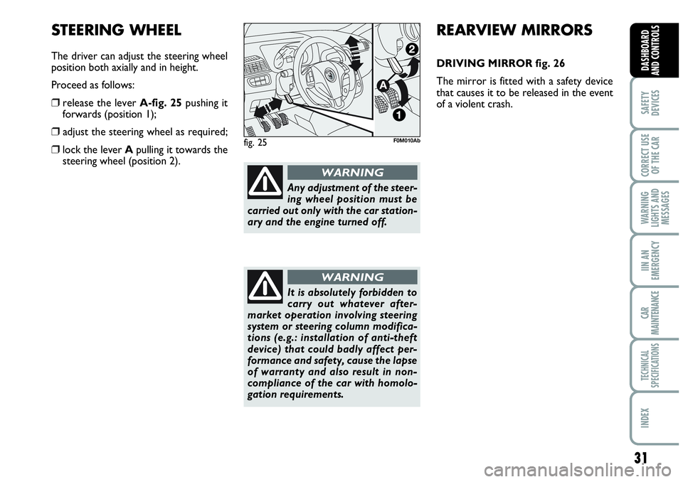
STEERING WHEEL
The driver can adjust the steering wheel
position both axially and in height.
Proceed as follows:
❒release the lever A-fig. 25pushing it
forwards (position 1);
❒ adjust the steering wheel as required;
❒lock the lever Apulling it towards the
steering wheel (position 2).fig. 25F0M010Ab
REARVIEW MIRRORS
DRIVING MIRROR fig. 26
The mirror is fitted with a safety device
that causes it to be released in the event
of a violent crash.
Any adjustment of the steer-
ing wheel position must be
carried out only with the car station-
ary and the engine turned off.
WARNING
It is absolutely forbidden to
carry out whatever after-
market operation involving steering
system or steering column modifica-
tions (e.g.: installation of anti-theft
device) that could badly affect per-
formance and safety, cause the lapse
of warranty and also result in non-
compliance of the car with homolo-
gation requirements.
WARNING
Page 44 of 207
42
SAFETY
DEVICES
CORRECT USE
OF THE CAR
WARNING
LIGHTS AND
MESSAGES
IN AN
EMERGENCY
CAR
MAINTENANCE
TECHNICAL
SPECIFICATIONS
INDEX
DASHBOARD
AND CONTROLS
During fully automatic operation, the on-
ly manual settings required are the fol-
lowing:
❒MONO, to align the air temperature
and distribution set on the passenger’s
side with that on the driver’s side;
❒•air recirculation, to keep it always
on or off;
❒-to speed up demisting/defrosting of
windscreen, side windows, rear window
and door mirrors;
❒
(to demist/defrost heated rear win-
dow and door mirrors.
During full automatic system operation,
you can change at any time set tempera-
tures, air distribution and fan speed by us-
ing the relevant buttons or knobs: the sys-
tem will automatically change its settings
to adjust to the new requirements.During (FULL AUTO) operation, chang-
ing air distribution and/or flow and/or
compressor activation and/or air recircu-
lation will make the FULLwording dis-
appear. In this way the system will keep
on controlling automatically all functions,
excluding those changed manually. Fan
speed is the same for every area of the
passenger compartment.
Air temperature adjusting
knobs H - N
Turning the knobs clockwise or counter-
clockwise, respectively highers or lowers
the temperature of the air required re-
spectively in the front left zone (knob N) or
in the right zone (knob H) of the passenger
compartment. Since the system controls
two zones of the passenger compartment,
it is possible to personalise required tem-
peratures (driver and passenger) with a
maximum difference of 7 °C. The temper-
atures set are shown on the displays near
the relevant knobs. Pressing button A
(MONO) automatically aligns the temper-
ature on the passenger’s side with that on
the driver’s side; you can therefore set the
same temperature for both zones by turn-
ing knob Non driver side. Separate oper-
ation of air temperatures and distribution is
restored by turning knobs Hor pressing
again button A(MONO) when the button
led is on.Turn the knobs fully clockwise or counter-
clockwise to engage respectively HI(max-
imum heating) or LO(maximum cooling).
To deactivate these two functions, just
turn the temperature knob and set the re-
quired temperature.
Front air distribution buttons I-M
Pressing these buttons it is possible to
choose manually one of the seven possi-
ble air distributions to the passenger com-
partment (right or left side):NAir flow to the windscreen and front
side window vents to demist or de-
frost them.
˙Air flow at central and side dashboard
vents to ventilate the chest and the
face during the hot season.
OAir flow towards the front and rear
lower parts of the passenger com-
partment. Due to the natural tenden-
cy of heat to spread upwards, this type
of distribution allows heating of the
passenger compartment in the short-
est time, also giving a prompt feeling
of warmth.
Page 56 of 207
54
SAFETY
DEVICES
CORRECT USE
OF THE CAR
WARNING
LIGHTS AND
MESSAGES
IN AN
EMERGENCY
CAR
MAINTENANCE
TECHNICAL
SPECIFICATIONS
INDEX
DASHBOARD
AND CONTROLS
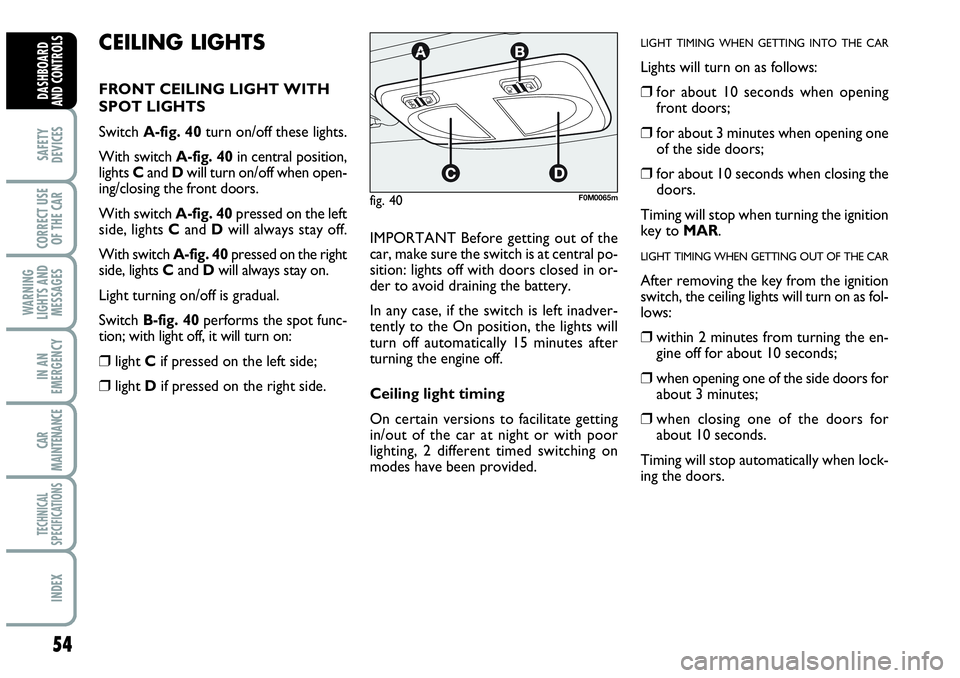
CEILING LIGHTS
FRONT CEILING LIGHT WITH
SPOT LIGHTS
Switch A-fig. 40turn on/off these lights.
With switch A-fig. 40in central position,
lights Cand Dwill turn on/off when open-
ing/closing the front doors.
With switch A-fig. 40pressed on the left
side, lights Cand Dwill always stay off.
With switch A-fig. 40pressed on the right
side, lights Cand Dwill always stay on.
Light turning on/off is gradual.
Switch B-fig. 40performs the spot func-
tion; with light off, it will turn on:
❒light Cif pressed on the left side;
❒light Dif pressed on the right side.IMPORTANT Before getting out of the
car, make sure the switch is at central po-
sition: lights off with doors closed in or-
der to avoid draining the battery.
In any case, if the switch is left inadver-
tently to the On position, the lights will
turn off automatically 15 minutes after
turning the engine off.
Ceiling light timing
On certain versions to facilitate getting
in/out of the car at night or with poor
lighting, 2 different timed switching on
modes have been provided.
LIGHT TIMING WHEN GETTING INTO THE CAR
Lights will turn on as follows:
❒for about 10 seconds when opening
front doors;
❒for about 3 minutes when opening one
of the side doors;
❒for about 10 seconds when closing the
doors.
Timing will stop when turning the ignition
key to MAR.
LIGHT TIMING WHEN GETTING OUT OF THE CAR
After removing the key from the ignition
switch, the ceiling lights will turn on as fol-
lows:
❒within 2 minutes from turning the en-
gine off for about 10 seconds;
❒when opening one of the side doors for
about 3 minutes;
❒when closing one of the doors for
about 10 seconds.
Timing will stop automatically when lock-
ing the doors.
fig. 40F0M0065m
Page 59 of 207
57
SAFETY
DEVICES
CORRECT USE
OF THE CAR
WARNING
LIGHTS AND
MESSAGES
IIN AN
EMERGENCY
CAR
MAINTENANCE
TECHNICAL
SPECIFICATIONS
INDEX
DASHBOARD
AND CONTROLS
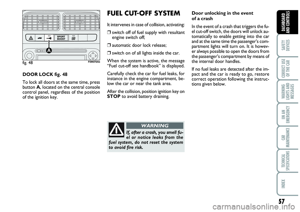
DOOR LOCK fig. 48
To lock all doors at the same time, press
button A, located on the central console
control panel, regardless of the position
of the ignition key.
FUEL CUT-OFF SYSTEM
It intervenes in case of collision, activating:
❒switch off of fuel supply with resultant
engine switch off;
❒automatic door lock release;
❒switch on of all lights inside the car.
When the system is active, the message
“Fuel cut-off see handbook” is displayed.
Carefully check the car for fuel leaks, for
instance in the engine compartment, be-
low the car or near the tank area.
After the collision, position ignition key on
STOPto avoid battery draining.
fig. 48F0M076Ab
Door unlocking in the event
of a crash
In the event of a crash that triggers the fu-
el cut-off switch, the doors will unlock au-
tomatically to enable getting into the car
and at the same time the passenger’s com-
partment lights will turn on. It is howev-
er always possible to open the doors from
the passenger’s compartment by means of
the internal door handles.
If no fuel leaks are detected after the im-
pact and the car is ready to go, restore
correct operation following the instruc-
tions given below.
If, after a crash, you smell fu-
el or notice leaks from the
fuel system, do not reset the system
to avoid fire risk.
WARNING
Page 65 of 207

63
SAFETY
DEVICES
CORRECT USE
OF THE CAR
WARNING
LIGHTS AND
MESSAGES
IIN AN
EMERGENCY
CAR
MAINTENANCE
TECHNICAL
SPECIFICATIONS
INDEX
DASHBOARD
AND CONTROLS
ANTI-CRUSHING SAFETY
SYSTEM
Sunroof is fitted with anti-crushing safety
system that detects the presence of an ob-
stacle during sunroof closing stroke and
that cuts in by stopping and reversing the
sunroof stroke.
INITIALISATION PROCEDURE
Sunroof shall be re-initialised after dis-
connecting the battery or if the relevant
protection fuse is blown.
Proceed as follows:
❒press button A-fig. 68at close posi-
tion;
❒keep the button pressed to close com-
pletely by steps the sunroof;
❒after full closing, wait for sunroof mo-
tor stopping.When leaving the car, the ignition key
should be removed to prevent the sun-
roof from being operated inadvertently
and harming anyone remaining in the car.
Improper use of the sunroof can be dan-
gerous. Before and during its operation
ensure that any passengers are not at risk
from the moving roof either by personal
objects getting caught in the mechanism
or by being injured by it directly.
EMERGENCY OPERATION
If the switch does not work, the sunroof
can be operated manually as follows:
❒remove the protection cap set between
the two sun curtains;
❒take the setscrew wrench (provided as
standard) from the tool bag in the boot;
❒fit the wrench into A-fig. 69and turn
it:
– clockwise to open the sunroof;
– counter-clockwise to close the sun-
roof.
fig. 69F0M0088m
Page 66 of 207
64
SAFETY
DEVICES
CORRECT USE
OF THE CAR
WARNING
LIGHTS AND
MESSAGES
IN AN
EMERGENCY
CAR
MAINTENANCE
TECHNICAL
SPECIFICATIONS
INDEX
DASHBOARD
AND CONTROLS
DOORS
CENTRAL DOOR
LOCKING/UNLOCKING SYSTEM
Locking from the outside
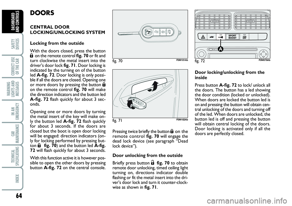
With the doors closed, press the button
Áon the remote control fig. 70 or fit and
turn clockwise the metal insert into the
driver’s door lock fig. 71. Door locking is
indicated by the turning on of the button
led A-fig. 72. Door locking is only possi-
ble if all the doors are closed. Opening one
or more doors by pressing the button
Áon the remote control fig. 70 will make
the direction indicators and the button led
A-fig. 72flash quickly for about 3 sec-
onds.
Opening one or more doors by turning
the metal insert of the key will make on-
ly the button led A-fig. 72flash quickly
for about 3 seconds. If the doors are
closed but the boot is open door locking
will be engaged: direction indicators (on-
ly for locking performed by pressing but-
ton
Áfig. 70) and the button led A-fig.
72will flash quickly for about 3 seconds.
With this function active it is however pos-
sible to open the other doors by pressing
button A-fig. 72on the central console.Pressing twice briefly the button
Áon the
remote control fig. 70 will engage the
dead lock device (see paragraph “Dead
lock device”).
Door unlocking from the outside
Briefly press button
Ëfig. 70to obtain
remote door unlocking, timed ceiling light
turning on, directions indicator double
flashing or fit the metal insert into the dri-
ver’s door lock and turn it counter-clock-
wise as shown in fig. 71.Door locking/unlocking from the
inside
Press button A-fig. 72to lock/ unlock all
the doors. The button has a led showing
the door condition (locked or unlocked).
When doors are locked the button led is
on and pressing the button will obtain cen-
tral unlocking of the doors and turning off
of the led. When doors are unlocked, the
button led is off and pressing the button
will obtain central locking of the doors.
Door locking is activated only if all the
doors are perfectly closed.
fig. 71F0M102Ab
fig. 72F0M076Abfig. 70F0M101Ab
Page 67 of 207

65
SAFETY
DEVICES
CORRECT USE
OF THE CAR
WARNING
LIGHTS AND
MESSAGES
IIN AN
EMERGENCY
CAR
MAINTENANCE
TECHNICAL
SPECIFICATIONS
INDEX
DASHBOARD
AND CONTROLS
After locking doors by:
❒remote control;
❒door revolving plug;
it will not be possible to unlock the doors
by pressing button
A-fig. 72set on the
dashboard.
IMPORTANT With central locking system
on, pulling the internal door handle of one
of the front doors will unlock that door.
Pulling the internal door handle of one of the
rear doors will unlock the relevant door.
Lacking power (blown fuse, battery discon-
nected, etc.) it is however possible to lock
the doors manually.
After exceeding 20 km/h speed, doors will
be locked automatically if the set up menu
function has been selected (see paragraph
“Multifunction display” in this section).
Once the dead lock device
has been actuated, doors
cannot be opened from the passen-
ger’s compartment in any way what-
soever. For this reason, make sure
there are no person left inside the car.
If the battery of the key with remote
control is down, the dead lock device
can be deactivated only by fitting the
metal insert of the key in both front
door revolving plugs as described pre-
viously. DEAD LOCK DEVICE
(for versions/markets,
where provided)
This safety device enables to inhibit:
❒door internal handles;
❒locking/unlocking button A-fig. 72;
thus hindering doors opening from inside
the passenger’s compartment in case of at-
tempt to break-into (e.g.: window breaking).
The dead lock device guarantees the best
protection against unwanted access.
Therefore, it should be actuated every
time the car is parked and left unattended.Device activation
The dead lock device is automatically ac-
tivated on every door when pressing twice
briefly the remote control button
Á,
fig. 70.
Device activation is indicated by 3 flashing
of direction indicators and flashing of the
button led A-fig. 72located on the dash-
board.
If one of the doors is not perfectly closed,
the dead lock device will not activate, thus
preventing that a person getting into the car
from the open door remains blocked inside
the passenger’s compartment when she/he
closes the door.
Device deactivation
The device is deactivated automatically on
every door in the following cases:
❒when opening the driver’s door using the
key without remote control;
❒when unlocking doors using the remote
control;
❒turning the ignition key to MAR.
WARNING
Page 70 of 207
68
SAFETY
DEVICES
CORRECT USE
OF THE CAR
WARNING
LIGHTS AND
MESSAGES
IN AN
EMERGENCY
CAR
MAINTENANCE
TECHNICAL
SPECIFICATIONS
INDEX
DASHBOARD
AND CONTROLS
BOOT
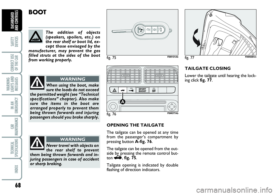
OPENING THE TAILGATE
The tailgate can be opened at any time
from the passenger’s compartment by
pressing button A-fig. 76.
The tailgate can be opened from the out-
side by pressing the remote control but-
ton
R, fig. 75.
Tailgate opening is indicated by double
flashing of direction indicators.TAILGATE CLOSING
Lower the tailgate until hearing the lock-
ing click fig. 77. The addition of objects
(speakers, spoilers, etc.) on
the rear shelf or boot lid, ex-
cept those envisaged by the
manufacturer, may prevent the gas
filled struts at the sides of the boot
from working properly.
When using the boot, make
sure the loads do not exceed
the permitted weight (see “Technical
specifications” chapter). Also make
sure the items in the boot are
arranged properly to prevent them
being thrown forwards and injuring
passengers should you brake sharply.
WARNING
Never travel with objects on
the rear shelf to prevent
them being thrown forwards and in-
juring passengers in case of accident
or sharp braking.
WARNING
fig. 75F0M101Ab
fig. 76F0M077Ab
fig. 77F0M0094m