boot Abarth Grande Punto 2010 Owner handbook (in English)
[x] Cancel search | Manufacturer: ABARTH, Model Year: 2010, Model line: Grande Punto, Model: Abarth Grande Punto 2010Pages: 207, PDF Size: 3.01 MB
Page 6 of 207
4
SAFETY
DEVICES
CORRECT USE
OF THE CAR
WARNING
LIGHTS AND
MESSAGES
IN AN
EMERGENCY
CAR
MAINTENANCE
TECHNICAL
SPECIFICATIONS
INDEX
DASHBOARD
AND CONTROLSDASHBOARD ...................................................................... 5
SYMBOLS ............................................................................... 7
THE FIAT CODE SYSTEM.................................................. 7
THE KEYS .............................................................................. 8
ALARM ................................................................................... 11
IGNITION DEVICE .............................................................. 12
INSTRUMENT PANEL ........................................................ 13
INSTRUMENTS..................................................................... 14
RECONFIGURABLE MULTIFUNCTION DISPLAY .... 16
TRIP COMPUTER ................................................................ 25
FRONT SEATS ..................................................................... 28
REAR SEATS .......................................................................... 29
HEAD RESTRAINTS............................................................. 30
STEERING WHEEL .............................................................. 31
REARVIEW MIRRORS......................................................... 31
CLIMATE CONTROL.......................................................... 33
MANUAL CLIMATE CONTROL SYSTEM .................... 34
AUTOMATIC TWO-ZONE CLIMATE
CONTROL SYSTEM ........................................................... 40
EXTERNAL LIGHTS............................................................. 47
WINDOW WASHING....................................................... 49
CRUISE CONTROL ............................................................ 52CEILING LIGHTS.................................................................. 54
CONTROLS ........................................................................... 55
FUEL CUT-OFF SWITCH .................................................. 57
INTERIOR FITTINGS........................................................... 58
SKY-DOME SUNROOF ..................................................... 62
DOORS .................................................................................. 64
POWER WINDOWS/WINDOW WINDERS .............. 66
BOOT ...................................................................................... 68
BONNET................................................................................. 71
ROOF RACK/SKI RACK .................................................... 73
HEADLIGHTS........................................................................ 74
ABS SYSTEM ......................................................................... 76
ESP SYSTEM .......................................................................... 78
EOBD SYSTEM ..................................................................... 83
TYRE PRESSURE MONITORING SYSTEM - T.P.M.S. . 84
SPORT BOOST..................................................................... 87
WIRING FOR NAVIGATION SYSTEM ......................... 88
ACCESSORIES PURCHASED BY THE OWNER .......... 88
AT THE FILLING STATION ............................................. 89
PROTECTING THE ENVIRONMENT............................. 90
D D
A A
S S
H H
B B
O O
A A
R R
D D
A A
N N
D D
C C
O O
N N
T T
R R
O O
L L
S S
Page 31 of 207

29
SAFETY
DEVICES
CORRECT USE
OF THE CAR
WARNING
LIGHTS AND
MESSAGES
IIN AN
EMERGENCY
CAR
MAINTENANCE
TECHNICAL
SPECIFICATIONS
INDEX
DASHBOARD
AND CONTROLS
Tilting the back rest fig. 22a
Pull handle Aupwards, the back rest will
tilt and the seat can slide forward by push-
ing the back rest.
Bringing back the back rest the seat will
return to its original position (mechani-
cal memory).
Check that the seat is firm-
ly locked in the runners by
trying to move it back and forth.
WARNING
fig. 22aF0M007Ab
REAR SEATS
To tilt rear seats refer to paragraph
“Extending the boot” in this section.
Upholstery of your car has
been designed to withstand
wear deriving from common
use of the car. You are how-
ever recommended to avoid strong
and/or continuous scratching with
clothing accessories such as metallic
buckles, studs, Velcro fastenings and
the like, since these items cause cir-
cumscribed stress of the cover fabric
that could lead to yarn breaking, and
damage the cover as a consequence.
fig. 22bF0M089Ab
Seat warming (for versions/
markets, where provided) fig. 22b
With ignition key at MAR, press button
Fto switch the seat warming on/off. The
led on the button will light up when the
function is on.
Page 57 of 207

55
SAFETY
DEVICES
CORRECT USE
OF THE CAR
WARNING
LIGHTS AND
MESSAGES
IIN AN
EMERGENCY
CAR
MAINTENANCE
TECHNICAL
SPECIFICATIONS
INDEX
DASHBOARD
AND CONTROLS
BOOT LIGHT fig. 41
For versions fitted with boot light, it will
turn on automatically when opening the
tailgate and it will turn off at closing.
PUDDLE LIGHTS fig. 42
These lights Aare located in the doors
and they will turn on when opening the
relevant door, regardless of the ignition
key position.
CONTROLS
HAZARD LIGHTS fig. 43
They turn on by pressing switch A, re-
gardless of the position of the ignition key.
When the device is on warning lights
Îand ¥on the cluster come on.
Press the switch again to turn the lights
off.
The use of hazard lights is governed by the
Highway Code of the country you are in.
Keep to the rules.
FRONT FOG LIGHTS fig. 44
To active, with front side lights on, press
button
5.
Warning light
5on the instrument pan-
el will turn on.
Press the button again to turn the lights
off.
The use of front fog lights is governed by
the Highway Code of the country you are
in. Keep to the rules.
fig. 41F0M0068m
fig. 42F0M0176m
fig. 43F0M073Ab
fig. 44F0M0070m
Page 63 of 207
61
SAFETY
DEVICES
CORRECT USE
OF THE CAR
WARNING
LIGHTS AND
MESSAGES
IIN AN
EMERGENCY
CAR
MAINTENANCE
TECHNICAL
SPECIFICATIONS
INDEX
DASHBOARD
AND CONTROLS
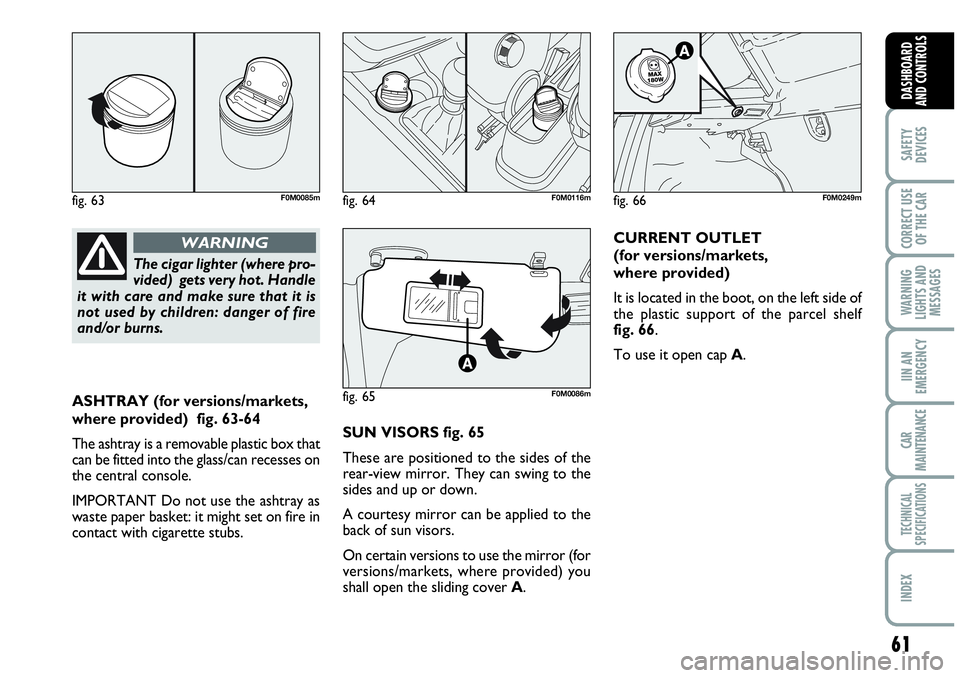
ASHTRAY (for versions/markets,
where provided) fig. 63-64
The ashtray is a removable plastic box that
can be fitted into the glass/can recesses on
the central console.
IMPORTANT Do not use the ashtray as
waste paper basket: it might set on fire in
contact with cigarette stubs.SUN VISORS fig. 65
These are positioned to the sides of the
rear-view mirror. They can swing to the
sides and up or down.
A courtesy mirror can be applied to the
back of sun visors.
On certain versions to use the mirror (for
versions/markets, where provided) you
shall open the sliding cover A.CURRENT OUTLET
(for versions/markets,
where provided)
It is located in the boot, on the left side of
the plastic support of the parcel shelf
fig. 66.
To use it open cap A.
The cigar lighter (where pro-
vided) gets very hot. Handle
it with care and make sure that it is
not used by children: danger of fire
and/or burns.
WARNING
fig. 63F0M0085m
fig. 65F0M0086m
fig. 66F0M0249mfig. 64F0M0116m
Page 65 of 207

63
SAFETY
DEVICES
CORRECT USE
OF THE CAR
WARNING
LIGHTS AND
MESSAGES
IIN AN
EMERGENCY
CAR
MAINTENANCE
TECHNICAL
SPECIFICATIONS
INDEX
DASHBOARD
AND CONTROLS
ANTI-CRUSHING SAFETY
SYSTEM
Sunroof is fitted with anti-crushing safety
system that detects the presence of an ob-
stacle during sunroof closing stroke and
that cuts in by stopping and reversing the
sunroof stroke.
INITIALISATION PROCEDURE
Sunroof shall be re-initialised after dis-
connecting the battery or if the relevant
protection fuse is blown.
Proceed as follows:
❒press button A-fig. 68at close posi-
tion;
❒keep the button pressed to close com-
pletely by steps the sunroof;
❒after full closing, wait for sunroof mo-
tor stopping.When leaving the car, the ignition key
should be removed to prevent the sun-
roof from being operated inadvertently
and harming anyone remaining in the car.
Improper use of the sunroof can be dan-
gerous. Before and during its operation
ensure that any passengers are not at risk
from the moving roof either by personal
objects getting caught in the mechanism
or by being injured by it directly.
EMERGENCY OPERATION
If the switch does not work, the sunroof
can be operated manually as follows:
❒remove the protection cap set between
the two sun curtains;
❒take the setscrew wrench (provided as
standard) from the tool bag in the boot;
❒fit the wrench into A-fig. 69and turn
it:
– clockwise to open the sunroof;
– counter-clockwise to close the sun-
roof.
fig. 69F0M0088m
Page 66 of 207
64
SAFETY
DEVICES
CORRECT USE
OF THE CAR
WARNING
LIGHTS AND
MESSAGES
IN AN
EMERGENCY
CAR
MAINTENANCE
TECHNICAL
SPECIFICATIONS
INDEX
DASHBOARD
AND CONTROLS
DOORS
CENTRAL DOOR
LOCKING/UNLOCKING SYSTEM
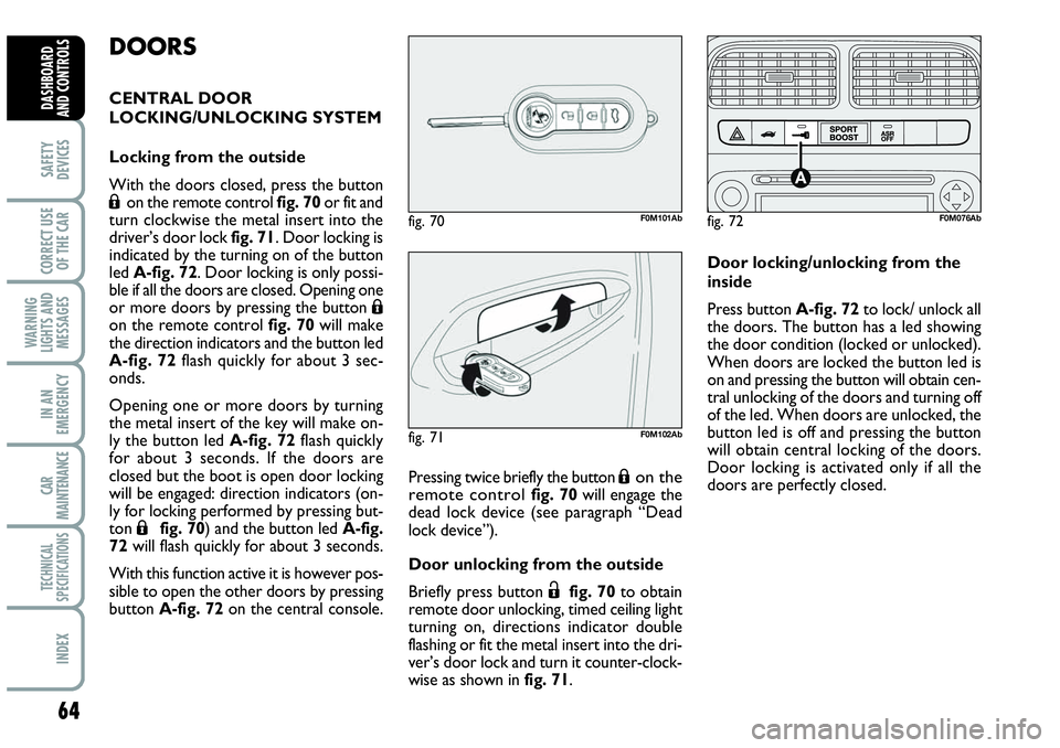
Locking from the outside
With the doors closed, press the button
Áon the remote control fig. 70 or fit and
turn clockwise the metal insert into the
driver’s door lock fig. 71. Door locking is
indicated by the turning on of the button
led A-fig. 72. Door locking is only possi-
ble if all the doors are closed. Opening one
or more doors by pressing the button
Áon the remote control fig. 70 will make
the direction indicators and the button led
A-fig. 72flash quickly for about 3 sec-
onds.
Opening one or more doors by turning
the metal insert of the key will make on-
ly the button led A-fig. 72flash quickly
for about 3 seconds. If the doors are
closed but the boot is open door locking
will be engaged: direction indicators (on-
ly for locking performed by pressing but-
ton
Áfig. 70) and the button led A-fig.
72will flash quickly for about 3 seconds.
With this function active it is however pos-
sible to open the other doors by pressing
button A-fig. 72on the central console.Pressing twice briefly the button
Áon the
remote control fig. 70 will engage the
dead lock device (see paragraph “Dead
lock device”).
Door unlocking from the outside
Briefly press button
Ëfig. 70to obtain
remote door unlocking, timed ceiling light
turning on, directions indicator double
flashing or fit the metal insert into the dri-
ver’s door lock and turn it counter-clock-
wise as shown in fig. 71.Door locking/unlocking from the
inside
Press button A-fig. 72to lock/ unlock all
the doors. The button has a led showing
the door condition (locked or unlocked).
When doors are locked the button led is
on and pressing the button will obtain cen-
tral unlocking of the doors and turning off
of the led. When doors are unlocked, the
button led is off and pressing the button
will obtain central locking of the doors.
Door locking is activated only if all the
doors are perfectly closed.
fig. 71F0M102Ab
fig. 72F0M076Abfig. 70F0M101Ab
Page 70 of 207
68
SAFETY
DEVICES
CORRECT USE
OF THE CAR
WARNING
LIGHTS AND
MESSAGES
IN AN
EMERGENCY
CAR
MAINTENANCE
TECHNICAL
SPECIFICATIONS
INDEX
DASHBOARD
AND CONTROLS
BOOT
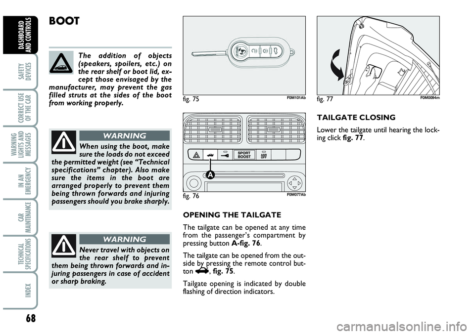
OPENING THE TAILGATE
The tailgate can be opened at any time
from the passenger’s compartment by
pressing button A-fig. 76.
The tailgate can be opened from the out-
side by pressing the remote control but-
ton
R, fig. 75.
Tailgate opening is indicated by double
flashing of direction indicators.TAILGATE CLOSING
Lower the tailgate until hearing the lock-
ing click fig. 77. The addition of objects
(speakers, spoilers, etc.) on
the rear shelf or boot lid, ex-
cept those envisaged by the
manufacturer, may prevent the gas
filled struts at the sides of the boot
from working properly.
When using the boot, make
sure the loads do not exceed
the permitted weight (see “Technical
specifications” chapter). Also make
sure the items in the boot are
arranged properly to prevent them
being thrown forwards and injuring
passengers should you brake sharply.
WARNING
Never travel with objects on
the rear shelf to prevent
them being thrown forwards and in-
juring passengers in case of accident
or sharp braking.
WARNING
fig. 75F0M101Ab
fig. 76F0M077Ab
fig. 77F0M0094m
Page 71 of 207

69
SAFETY
DEVICES
CORRECT USE
OF THE CAR
WARNING
LIGHTS AND
MESSAGES
IIN AN
EMERGENCY
CAR
MAINTENANCE
TECHNICAL
SPECIFICATIONS
INDEX
DASHBOARD
AND CONTROLS
TAILGATE EMERGENCY
OPENING fig. 78
To open the tailgate from the passenger’s
compartment if the car battery is flat or
the electric tailgate lock is faulty, proceed
as follows:
❒tilt the rear seats (see paragraph “Ex-
tending the boot” in this section);
❒press lever Bin the boot.Total extension fig. 80
Tilt the rear seat completely to obtain
maximum boot extension.Proceed as follows:
❒lower completely the rear seat head re-
straints;
❒check that the seat belt is not twisted;
❒tilt cushions;
❒lift handles Aand B-fig. 79to release
the backrests and guide them onto the
cushion.
IMPORTANT If after tilting the rear seat,
you have to remove the rear parcel shelf,
position it as shown in fig. 82.
fig. 78F0M0095mfig. 79F0M086Abfig. 80F0M087Ab
Page 72 of 207
70
SAFETY
DEVICES
CORRECT USE
OF THE CAR
WARNING
LIGHTS AND
MESSAGES
IN AN
EMERGENCY
CAR
MAINTENANCE
TECHNICAL
SPECIFICATIONS
INDEX
DASHBOARD
AND CONTROLS
fig. 83F0M0101m
fig. 82F0M020Abfig. 81F0M088Abfig. 84F0M0222m
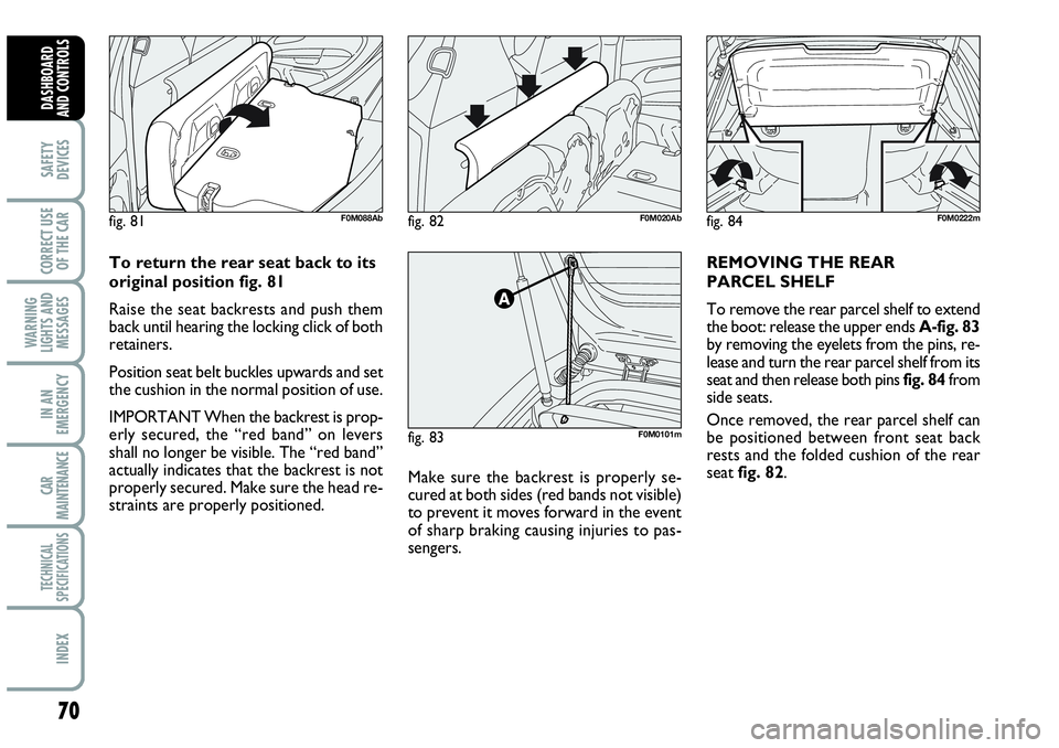
Make sure the backrest is properly se-
cured at both sides (red bands not visible)
to prevent it moves forward in the event
of sharp braking causing injuries to pas-
sengers. To return the rear seat back to its
original position fig. 81
Raise the seat backrests and push them
back until hearing the locking click of both
retainers.
Position seat belt buckles upwards and set
the cushion in the normal position of use.
IMPORTANT When the backrest is prop-
erly secured, the “red band” on levers
shall no longer be visible. The “red band”
actually indicates that the backrest is not
properly secured. Make sure the head re-
straints are properly positioned.REMOVING THE REAR
PARCEL SHELF
To remove the rear parcel shelf to extend
the boot: release the upper ends A-fig. 83
by removing the eyelets from the pins, re-
lease and turn the rear parcel shelf from its
seat and then release both pins fig. 84from
side seats.
Once removed, the rear parcel shelf can
be positioned between front seat back
rests and the folded cushion of the rear
seat fig. 82.
Page 73 of 207
71
SAFETY
DEVICES
CORRECT USE
OF THE CAR
WARNING
LIGHTS AND
MESSAGES
IIN AN
EMERGENCY
CAR
MAINTENANCE
TECHNICAL
SPECIFICATIONS
INDEX
DASHBOARD
AND CONTROLS
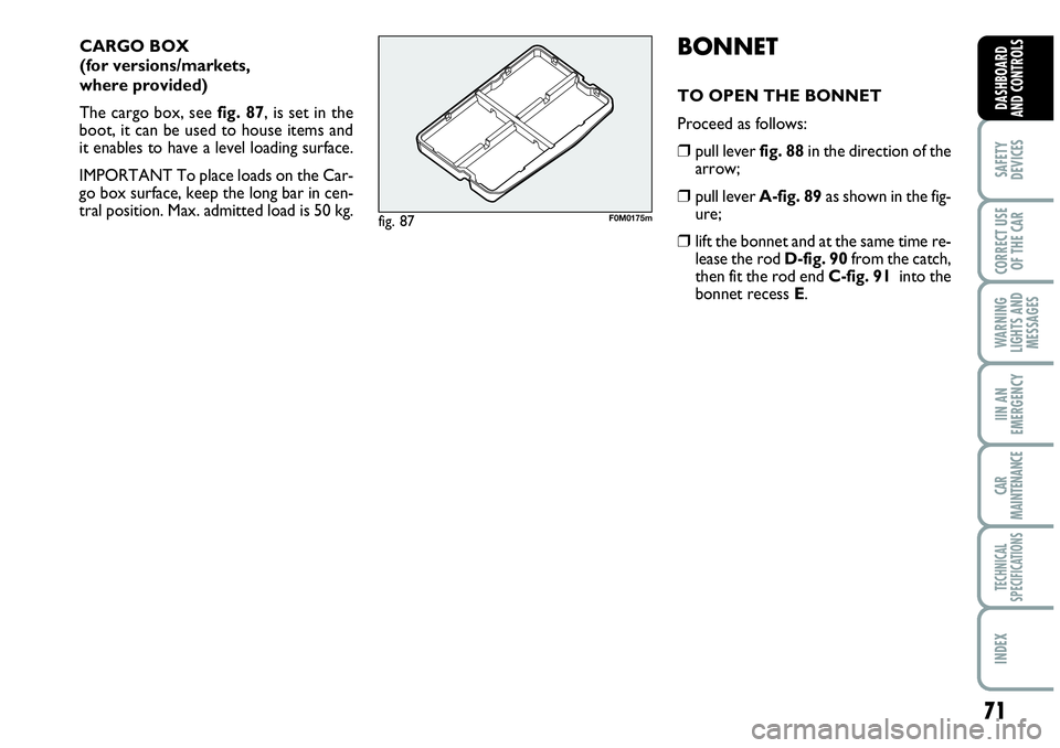
CARGO BOX
(for versions/markets,
where provided)
The cargo box, see fig. 87, is set in the
boot, it can be used to house items and
it enables to have a level loading surface.
IMPORTANT To place loads on the Car-
go box surface, keep the long bar in cen-
tral position. Max. admitted load is 50 kg.BONNET
TO OPEN THE BONNET
Proceed as follows:
❒pull lever fig. 88in the direction of the
arrow;
❒pull lever A-fig. 89as shown in the fig-
ure;
❒lift the bonnet and at the same time re-
lease the rod D-fig. 90from the catch,
then fit the rod end C-fig. 91 into the
bonnet recess E.
fig. 87F0M0175m