instrument panel Abarth Grande Punto 2010 Owner handbook (in English)
[x] Cancel search | Manufacturer: ABARTH, Model Year: 2010, Model line: Grande Punto, Model: Abarth Grande Punto 2010Pages: 207, PDF Size: 3.01 MB
Page 6 of 207
4
SAFETY
DEVICES
CORRECT USE
OF THE CAR
WARNING
LIGHTS AND
MESSAGES
IN AN
EMERGENCY
CAR
MAINTENANCE
TECHNICAL
SPECIFICATIONS
INDEX
DASHBOARD
AND CONTROLSDASHBOARD ...................................................................... 5
SYMBOLS ............................................................................... 7
THE FIAT CODE SYSTEM.................................................. 7
THE KEYS .............................................................................. 8
ALARM ................................................................................... 11
IGNITION DEVICE .............................................................. 12
INSTRUMENT PANEL ........................................................ 13
INSTRUMENTS..................................................................... 14
RECONFIGURABLE MULTIFUNCTION DISPLAY .... 16
TRIP COMPUTER ................................................................ 25
FRONT SEATS ..................................................................... 28
REAR SEATS .......................................................................... 29
HEAD RESTRAINTS............................................................. 30
STEERING WHEEL .............................................................. 31
REARVIEW MIRRORS......................................................... 31
CLIMATE CONTROL.......................................................... 33
MANUAL CLIMATE CONTROL SYSTEM .................... 34
AUTOMATIC TWO-ZONE CLIMATE
CONTROL SYSTEM ........................................................... 40
EXTERNAL LIGHTS............................................................. 47
WINDOW WASHING....................................................... 49
CRUISE CONTROL ............................................................ 52CEILING LIGHTS.................................................................. 54
CONTROLS ........................................................................... 55
FUEL CUT-OFF SWITCH .................................................. 57
INTERIOR FITTINGS........................................................... 58
SKY-DOME SUNROOF ..................................................... 62
DOORS .................................................................................. 64
POWER WINDOWS/WINDOW WINDERS .............. 66
BOOT ...................................................................................... 68
BONNET................................................................................. 71
ROOF RACK/SKI RACK .................................................... 73
HEADLIGHTS........................................................................ 74
ABS SYSTEM ......................................................................... 76
ESP SYSTEM .......................................................................... 78
EOBD SYSTEM ..................................................................... 83
TYRE PRESSURE MONITORING SYSTEM - T.P.M.S. . 84
SPORT BOOST..................................................................... 87
WIRING FOR NAVIGATION SYSTEM ......................... 88
ACCESSORIES PURCHASED BY THE OWNER .......... 88
AT THE FILLING STATION ............................................. 89
PROTECTING THE ENVIRONMENT............................. 90
D D
A A
S S
H H
B B
O O
A A
R R
D D
A A
N N
D D
C C
O O
N N
T T
R R
O O
L L
S S
Page 7 of 207
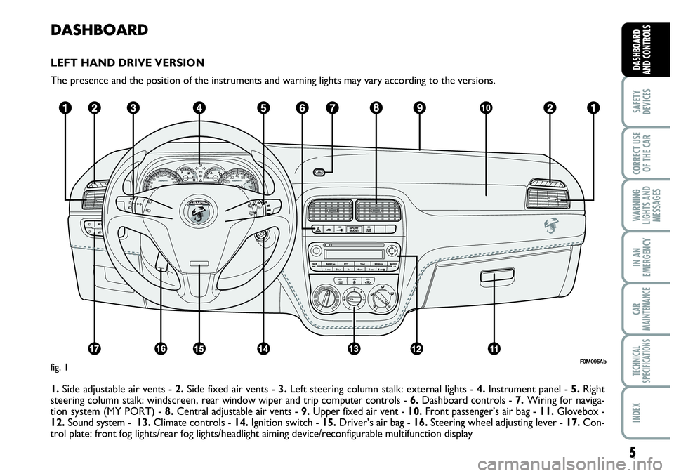
DASHBOARD
LEFT HAND DRIVE VERSION
The presence and the position of the instruments and warning lights may vary according to the versions.
1. Side adjustable air vents - 2.Side fixed air vents - 3.Left steering column stalk: external lights - 4.Instrument panel - 5.Right
steering column stalk: windscreen, rear window wiper and trip computer controls - 6.Dashboard controls -7.Wiring for naviga-
tion system (MY PORT) - 8.Central adjustable air vents - 9.Upper fixed air vent - 10.Front passenger’s air bag - 11.Glovebox -
12.Sound system - 13.Climate controls - 14.Ignition switch - 15.Driver’s air bag - 16.Steering wheel adjusting lever - 17.Con-
trol plate: front fog lights/rear fog lights/headlight aiming device/reconfigurable multifunction display
5
SAFETY
DEVICES
CORRECT USE
OF THE CAR
WARNING
LIGHTS AND
MESSAGES
IN AN
EMERGENCY
CAR
MAINTENANCE
TECHNICAL
SPECIFICATIONS
INDEX
DASHBOARD
AND CONTROLS
F0M095Abfig. 1
Page 8 of 207
6
SAFETY
DEVICES
CORRECT USE
OF THE CAR
WARNING
LIGHTS AND
MESSAGES
IN AN
EMERGENCY
CAR
MAINTENANCE
TECHNICAL
SPECIFICATIONS
INDEX
DASHBOARD
AND CONTROLS
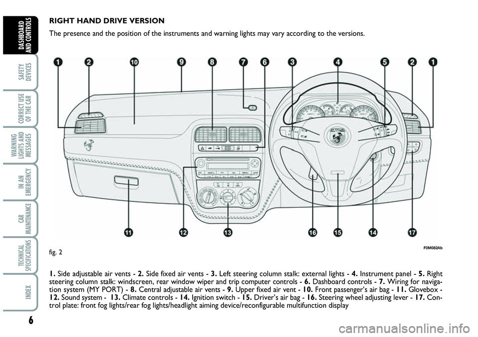
RIGHT HAND DRIVE VERSION
The presence and the position of the instruments and warning lights may vary according to the versions.
1. Side adjustable air vents - 2.Side fixed air vents - 3.Left steering column stalk: external lights - 4.Instrument panel - 5.Right
steering column stalk: windscreen, rear window wiper and trip computer controls - 6.Dashboard controls -7.Wiring for naviga-
tion system (MY PORT) - 8.Central adjustable air vents - 9.Upper fixed air vent - 10.Front passenger’s air bag - 11.Glovebox -
12.Sound system - 13.Climate controls - 14.Ignition switch - 15.Driver’s air bag - 16.Steering wheel adjusting lever - 17.Con-
trol plate: front fog lights/rear fog lights/headlight aiming device/reconfigurable multifunction display
F0M082Abfig. 2
Page 15 of 207
13
SAFETY
DEVICES
CORRECT USE
OF THE CAR
WARNING
LIGHTS AND
MESSAGES
IN AN
EMERGENCY
CAR
MAINTENANCE
TECHNICAL
SPECIFICATIONS
INDEX
DASHBOARD
AND CONTROLS
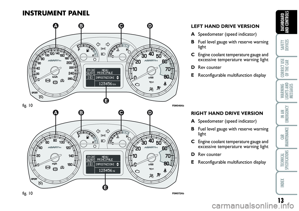
INSTRUMENT PANEL
LEFT HAND DRIVE VERSION
ASpeedometer (speed indicator)
BFuel level gauge with reserve warning
light
CEngine coolant temperature gauge and
excessive temperature warning light
DRev counter
EReconfigurable multifunction display
F0M049Abfig. 10
RIGHT HAND DRIVE VERSION
ASpeedometer (speed indicator)
BFuel level gauge with reserve warning
light
CEngine coolant temperature gauge and
excessive temperature warning light
DRev counter
EReconfigurable multifunction display
F0M072Abfig. 10
Page 49 of 207
47
SAFETY
DEVICES
CORRECT USE
OF THE CAR
WARNING
LIGHTS AND
MESSAGES
IIN AN
EMERGENCY
CAR
MAINTENANCE
TECHNICAL
SPECIFICATIONS
INDEX
DASHBOARD
AND CONTROLS
EXTERNAL LIGHTS
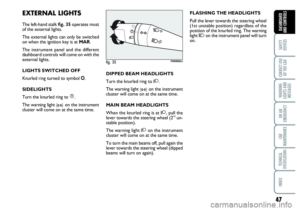
The left-hand stalk fig. 35operates most
of the external lights.
The external lights can only be switched
on when the ignition key is at MAR.
The instrument panel and the different
dashboard controls will come on with the
external lights.
LIGHTS SWITCHED OFF
Knurled ring turned to symbol O.
SIDELIGHTS
Turn the knurled ring to
6.
The warning light
3on the instrument
cluster will come on at the same time.DIPPED BEAM HEADLIGHTS
Turn the knurled ring to
2.
The warning light
3on the instrument
cluster will come on at the same time.
MAIN BEAM HEADLIGHTS
When the knurled ring is at
2, pull the
lever towards the steering wheel (2ndun-
stable position).
The warning light
2on the instrument
cluster will come on at the same time.
To turn the main beams off, pull again the
lever towards the steering wheel (dipped
beams will turn on again).FLASHING THE HEADLIGHTS
Pull the lever towards the steering wheel
(1st unstable position) regardless of the
position of the knurled ring. The warning
light
1on the instrument panel will turn
on.
fig. 35F0M0060m
Page 50 of 207
48
SAFETY
DEVICES
CORRECT USE
OF THE CAR
WARNING
LIGHTS AND
MESSAGES
IN AN
EMERGENCY
CAR
MAINTENANCE
TECHNICAL
SPECIFICATIONS
INDEX
DASHBOARD
AND CONTROLS
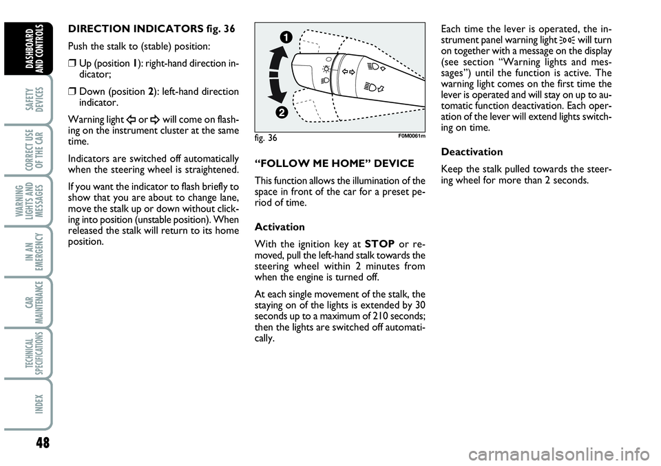
DIRECTION INDICATORS fig. 36
Push the stalk to (stable) position:
❒Up (position 1): right-hand direction in-
dicator;
❒Down (position 2): left-hand direction
indicator.
Warning light
Îor ¥will come on flash-
ing on the instrument cluster at the same
time.
Indicators are switched off automatically
when the steering wheel is straightened.
If you want the indicator to flash briefly to
show that you are about to change lane,
move the stalk up or down without click-
ing into position (unstable position). When
released the stalk will return to its home
position.“FOLLOW ME HOME” DEVICE
This function allows the illumination of the
space in front of the car for a preset pe-
riod of time.
Activation
With the ignition key at STOPor re-
moved, pull the left-hand stalk towards the
steering wheel within 2 minutes from
when the engine is turned off.
At each single movement of the stalk, the
staying on of the lights is extended by 30
seconds up to a maximum of 210 seconds;
then the lights are switched off automati-
cally. Each time the lever is operated, the in-
strument panel warning light
3will turn
on together with a message on the display
(see section “Warning lights and mes-
sages”) until the function is active. The
warning light comes on the first time the
lever is operated and will stay on up to au-
tomatic function deactivation. Each oper-
ation of the lever will extend lights switch-
ing on time.
Deactivation
Keep the stalk pulled towards the steer-
ing wheel for more than 2 seconds.
fig. 36F0M0061m
Page 54 of 207

52
SAFETY
DEVICES
CORRECT USE
OF THE CAR
WARNING
LIGHTS AND
MESSAGES
IN AN
EMERGENCY
CAR
MAINTENANCE
TECHNICAL
SPECIFICATIONS
INDEX
DASHBOARD
AND CONTROLS
CRUISE CONTROL
(constant speed
regulator)
(for versions/markets,
where provided)
It is a device able to support the driver,
with electronic control, which allows dri-
ving at speed over 30 km/h on long and
straight dry roads (e.g.: motorways), at a
desired speed, without pressing the ac-
celerator pedal. Therefore it is not sug-
gested to use this device on extra-urban
roads with traffic. Do not use it in town.DEVICE ENGAGEMENT
Turn knob A-fig. 39to ON.
The Cruise Control cannot be engaged
in first or reverse gear. It is advisable to
engage it in 4th or higher gears.
Travelling downhill with the device en-
gaged, the car speed may increase more
than the memorised one.
When the device is activated the warn-
ing light
Üturns on together with the rel-
evant message on the instrument panel
(for versions/markets, where provided).TO MEMORISE SPEED
Proceed as follows:
❒turn knob A-fig. 39to ONand press
the accelerator pedal to the required
speed;
❒move the stalk upwards (+) for at
least one second, then release it. The
car speed is memorised and it is
therefore possible to release the ac-
celerator pedal.
In the case of need (when overtaking for
instance) acceleration is possible simply
pressing the accelerator pedal: releasing
the accelerator pedal, the car will return
to the speed memorised previously.
fig. 39F0M0064m
Page 58 of 207

56
SAFETY
DEVICES
CORRECT USE
OF THE CAR
WARNING
LIGHTS AND
MESSAGES
IN AN
EMERGENCY
CAR
MAINTENANCE
TECHNICAL
SPECIFICATIONS
INDEX
DASHBOARD
AND CONTROLS
HEATED REAR WINDOW fig. 47
Press button Ato turn on this function.
This function will turn off automatically af-
ter about 20 minutes. REAR FOG LIGHT fig. 45
Press button 4, to turn these lights on it
is necessary to have the dipped beam head-
lights or the front fog lights (for versions/
markets, where provided) switched on.
Warning light 4on the instrument panel
will turn on.
Press the button again to turn the light off
or turn off dipped beams and/or front fog
lights (for versions/markets, where pro-
vided).
The use of rear fog lights is governed by the
Highway Code of the country you are in.
Keep to the rules.
PARKING LIGHTS
These lights can only be turned on with ig-
nition key at STOP or removed, by mov-
ing the left stalk knurled ring first to Oand
then to
6or 2.
The warning light
3on the instrument
cluster will come on at the same time.SPORT BOOST fig. 46
Press the Abutton to start the “SPORT
BOOST” function (see “SPORT BOO-
ST” paragraph in the herein section). On-
ce this function has been started, the
“SPORT” warning light on the instru-
ment board panel turns on. Press the A
button again to switch this function off.
fig. 45F0M0071mfig. 47F0M0038mfig. 46F0M074Ab
Page 76 of 207
74
SAFETY
DEVICES
CORRECT USE
OF THE CAR
WARNING
LIGHTS AND
MESSAGES
IN AN
EMERGENCY
CAR
MAINTENANCE
TECHNICAL
SPECIFICATIONS
INDEX
DASHBOARD
AND CONTROLS
HEADLIGHTS
ADJUSTING THE
HEADLIGHT BEAM
Proper adjustment of the headlight beams
is of vital importance for your safety and
comfort and also for the other road users.
To ensure you and other drivers have the
best visibility conditions when travelling
with the headlights on, the headlights must
be set properly. Contact Abarth Dealer-
ship to have the headlights properly ad-
justed.HEADLIGHT AIMING DEVICE
It works with ignition key at MARand
dipped beams on. When the car is loaded,
it slopes backwards. This means that the
headlight beam rises. In this case, it is nec-
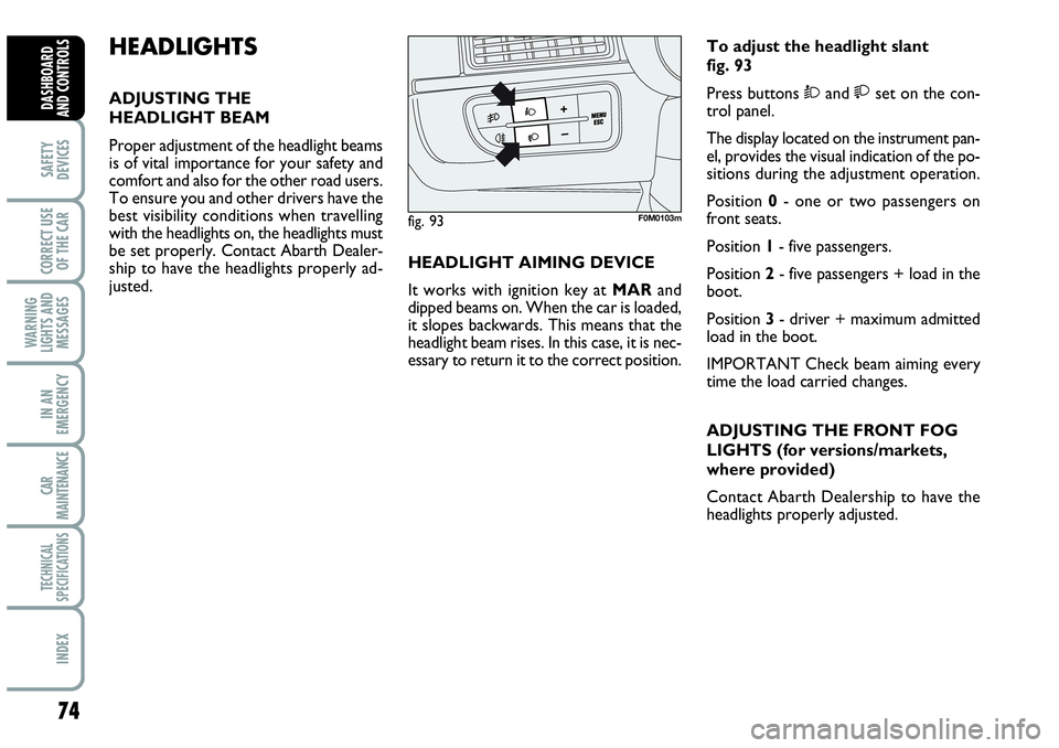
essary to return it to the correct position.To adjust the headlight slant
fig. 93
Press buttons Òand set on the con-
trol panel.
The display located on the instrument pan-
el, provides the visual indication of the po-
sitions during the adjustment operation.
Position 0- one or two passengers on
front seats.
Position 1- five passengers.
Position 2- five passengers + load in the
boot.
Position 3- driver + maximum admitted
load in the boot.
IMPORTANT Check beam aiming every
time the load carried changes.
ADJUSTING THE FRONT FOG
LIGHTS (for versions/markets,
where provided)
Contact Abarth Dealership to have the
headlights properly adjusted.
fig. 93F0M0103m
Page 79 of 207
77
SAFETY
DEVICES
CORRECT USE
OF THE CAR
WARNING
LIGHTS AND
MESSAGES
IIN AN
EMERGENCY
CAR
MAINTENANCE
TECHNICAL
SPECIFICATIONS
INDEX
DASHBOARD
AND CONTROLS
FAILURE INDICATIONS
ABS failure
ABS failure is indicated by the turning on
of warning light
>on the instrument pan-
el together with the dedicated message on
the multifunction display (for versions/
markets, where provided), (see section
“Warning lights and messages”).
In this case the braking system is still effi-
cient, though without the aid of the ABS
system. Drive carefully to the closest
Abarth Dealership to have the system
checked.EBD failure
EBD failure is indicated by the turning on
of warning lights
>and xon the in-
strument panel together with the dedi-
cated message on the multifunction dis-
play (where provided), (see section
“Warning lights and messages”).
In this case with sharp braking the rear
wheels might lock too early, with the pos-
sibility of skidding. Drive extremely care-
fully to the nearest Abarth Dealership to
have the system checked.If warning light xalone
comes on (together with the
message on the multifunction display,
where provided), stop the car imme-
diately and contact the nearest Abarth
Dealership. Fluid leaks from the hy-
draulic system, in fact, can compromise
the braking system, both traditional
systems and systems with ABS.
WARNING