sensor ACURA INTEGRA 1994 Service Repair Manual
[x] Cancel search | Manufacturer: ACURA, Model Year: 1994, Model line: INTEGRA, Model: ACURA INTEGRA 1994Pages: 1413, PDF Size: 37.94 MB
Page 53 of 1413

*l
Engine Removal/lnstallation
(cont'dl
27. Remove the radiator assembly {see page 1O-4),
28. Remove the A/C compressor.
a Do not disconnect A/C hoses.
8 x '1.25 mm24 N.m t2.4 kgf.m, 17 lbl.ftl
29. Disconnect the heated oxygen sensor (HO2Sl con-nector, then remove exhaust pipe A.
B'l8Cl engine: Ho2s
I x 1.25 mm24 N.m (2.4 kgf.m,17 rbt.ftt
Replace.
SELF-LOCKING NUT8 x 1.25 mm16 N.m 11.6 kgf.m,12 tbl.ftlReplace.
EXHAUSTPIPE A
SELF10 x 1.25 mm54 N.m (5.5 ksf.m.4O lbf'ltlReplace.
CONNECTOR
5-8
8188l engine:
8 x 1.25 mm24 N.m 12.4 kgf.m,17 tbt.trl
GASKETReplace.
GASKETReplace.
SELF.LOCKING NUTI x 1.25 mm16 N.m (1.6 kgt.m,12 tbf.ft)Replace.10 x 1.25 mm54 N.m (5.5 kgl.m,40 tbt.ttlReplace.
30. Remove the shift rod and extension rod {M/T).
I x 1.25 mm22 N-m 12.2 kgf.m, '16 lbf.ftlSHIFT ROD
Page 79 of 1413

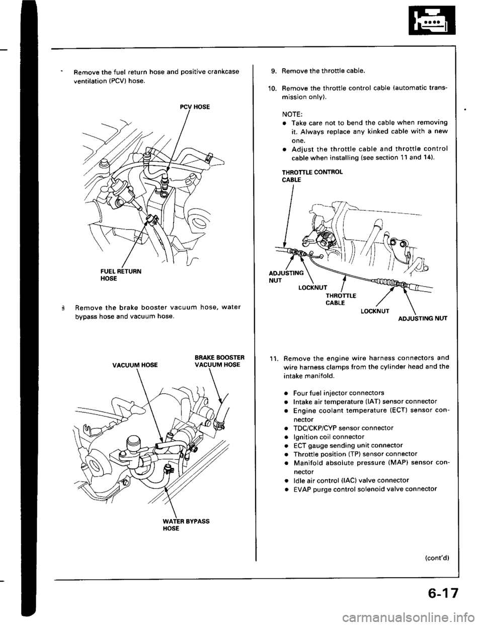
Remove the fuel return hose and positive crankcase
ventilation (PCV) hose.
Remove the brake booster vacuum hose, water
bypass hose and vacuum hose.
ERAKE BOOSTERVACUUM HOSE
HOSE
VACUUM HOSE
HOSE
9.
10.
Remove the throttle cable.
Remove the throttle control cable (automatic trans-
mission only).
NOTE:
. Take care not to bend the cable when removing
it. Always replace any kinked cable with a new
one.
. Adjust the throttle cable and throttle control
cable when installing (see section 11 and 14).
THROTTLE CONTROLCABLE
Remove the engine wire harness connectors and
wire harness clamps trom the cylinder head and the
intake manifold.
Four fuel injector connectors
Intake air temperature (lAT) sensor connector
Engine coolant temperature (ECT) sensor con-
necror
TDC/CKP/CYP sensor connector
lgnition coil connector
ECT gauge sending unit connector
Throttle position (TP) sensor connector
Manifold absolute Dressure (MAP) sensor con-
nector
ldle air control (lAC) valve connector
EVAP purge control solenoid valve connector
11.
a
a
a
a
a
a
a
a
a
(cont'dl
ATI'USTING
6-17
Page 118 of 1413

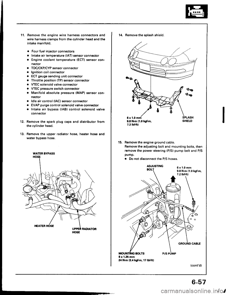
ll.Remove the engine wire harness connectors and
wi.e ha.ness clamps from the cylinder head and the
intake manitold.
Four fuel injector connectors
Intake air tempe.ature {lAT) sensor connector
Engine coolant temperature (ECT) sensor con-
nector
TDC/CKP/CYP sensor connector
lgnition coil conn€ctor
ECT gauge sending unit connector
Throttle position (TP) sensor connector
VTEC solenoid valve connector
VTEC Dressure switch connector
Manifold absolute pressure (MAP) sensor con-
nector
ldle air control {lAC) sensor connector
EVAP purge controlsol€noid valvo connector
Intake air bypass {lABl control solenoid valve
conneclor
a
o
a
o
a
a
a
a
a
a
a
a
a
12.
13.
Remove the spsrk plug caps and distributor from
the cylinder head.
Remove the upper radiator hose, heat€r hose and
water bypass hose.
WATER BYPASS
HOSE
6r1.0mm9.8 N.m (1.0 kgt m,1.2 tbtftl
14. Remove the sDlash shield.
Remove the engine ground cable.
Romovo the adjusting bolt and mounting bolts, then
remove the power steering (P/S) pump belt and P/Spump.
. Do not disconnect the P/S hoses.
(cont'dl
15.
6x1.0mm9.8 N.m 11.0 kgl.m,7.2 tbt.ttl
6-57
,l
Page 180 of 1413

Intake Manifold
Replacement
NOTE: Use new O-rings and gaskets when reassembling.
CAUTION: Check for tolds or scratches on the aurface ot the gasket. Roplace with a now gasket it damagod,
81881 engine:
5r0.8mm6 N'm {0.6 kgl.m.4 rbr.ftlINTAKE AIRTEMPERATUREIIATI SENSOR
'*o*ot'u""'""N
5xO.8mm6 .m (0.6 kg{.m.4 tbf.ftl
O-RINGReplace.
IiITAKE MANIFOLDReplace iI cracked orit mating s!rtaces arodamag€o.
PURGE CONTROLSOLENOID VALVE
8 x 1.25 mm22 N.r 12.2 kgl.m,'16 tbt.ftt
IDLE AIR
GASKETSReplace.
I x 1.25 mm20 N.m (2.0 kgt.m.14 rbf.ftl
O.RINGReplace.{IACI VALVEBe careful notto damage.THROTTLE
8 x 1.25 mm
BODY
O-RINGSBeplace.
24 N.m (2.4 kgf'm,17 rbf.ft)
8 x 1.25 mm23 N.m (2.3 kgl.m,17 lbf.frl
BRACKET"o
aYc
g
/
1.25 mmN.m (2.4 kgl'm,rbf'ft1
8x2417
8 x 1.25 mm24 N.m (2.4 kgl'm.17 tbr.ftlTHERMOVALVE8e careful not todamage.
9-2
Page 181 of 1413

NOTE: Use new O-rings and gaskets when reassembling.
CAUTION: Chock for folds 01 scratches on th6 surfac6 of tho gaskot. Replace wilh a new gasket if damaged.
818C1 engino:
INTAKE MANIFOLDReplace il cracked oril mating surfaces are
5 x O.8 rnm6 N.m 10.6 kgl.m,4 tbt.ttl
lI
{,/
?,/
EVAP PURGE CONTROLVALVEdamageo.
IAT SENSOR
5xO.8mm6 N.m 10.6 kgf.m,4 tbf.ftl
INTAKE AIRBYPASS VALVE
IAC VALVEBe carelul notlo oamage.
O.RINGSReplace.
GASKETSReplace.
O.BI GReplace.
BODY
INTAKE MANIFOLDCHAMBER
8 x 1.25 mm23 N.rn 12.3 kgt'm,17 tbf.frl
I x 1.25 mm22 N.m 12.2 kgl.ft,t6 tbt.tt)
BRACKET
8 r 1.25 mm24 N.m {2.4 kgf.h,t7 rbr.ftl
8 x t.25 mfi24 N.m (2.4 lgf.m.17 tbt.ft)I r 1.25 lnm24 N.m 12.4 kgt.m,17 tbt.ftl
8 x 1.25 mm20 .m (2.0 kgt.m,14 tbf.ftl
THROTTLEAODY
FAST IDL€ THERMO VALVEBe carelul not to damage.
HEATER BYPASSPIPE
o-Rt GsReplace.
I x 1.25 mm24 N.m (2.4 kgl.m, 17lbf'ft|
9-3
Page 183 of 1413

Exhaust Pipe and Muffler
Replacement
NOTE: Use new gaskets and
Bl88l engine:
selflocking nuts when reassembling.
HEAT SHIELDS
6 x 1.0 mm9.8 N.m l1.O kgf.m, 7.2 lbf.ftl
HEAT SHI€LD
SELF-LOCKIIIG NUT
,@\
10 x 1.25 mm33 N.m (3.4 kgt.m,25 tbf.fttReplace.HEATEO OXYGENSENSOR (HO2Sl
44 N.m 14.5 kgt.m,33 rbf.ftlI x 1.25 mm24 N.m 12.4 kgf.m,17 tbl.frl
BRACKET
GASKETSReplace.
SELF-LOCKING NUTS10 x 1,25 mm54 N'm 15.5 kgf'm,40 tbf.ftlReplace.
SELF-LOCKING NUT8 x 1.25 mm16 N.m {1.6 kgf.m,r2 tbt.frlReplace.
I x 1.25 mm22 N.m (2.2 kgl.m, r6lbt.ftlReplace.Tighten the flange nuts in steps,alternating side-to-side.
MUFFLER
EXHAUST
I,
^1
e
e
8 x 1.25 mm22 N.m 12.2 kgt.m, 16 lbf.ftlReplace.Tighten the bolts in steps,alternating side-to-side.
COVER
GASKETReplace.
THREE WAYCATALYTICCONVERTER
COVER
6 x 1.0 mm9.8 N.m l1.O kgf.m, 7.2 lbl.ttl
PIPE TIP
(cont'd)
Page 192 of 1413
![ACURA INTEGRA 1994 Service Repair Manual Water Pump
NOTE:
a Use new O-rings and new special bolts when reassembling.
a Use liquid gasket, Part No. O8718-0OO1.
3;iil3 B18c1 onsino:
ECT GAUGE SEDING U]{ITI N.m (0.9 tgf.n, 7 lbftt)Apply liquid ACURA INTEGRA 1994 Service Repair Manual Water Pump
NOTE:
a Use new O-rings and new special bolts when reassembling.
a Use liquid gasket, Part No. O8718-0OO1.
3;iil3 B18c1 onsino:
ECT GAUGE SEDING U]{ITI N.m (0.9 tgf.n, 7 lbftt)Apply liquid](/img/32/56982/w960_56982-191.png)
Water Pump
NOTE:
a Use new O-rings and new special bolts when reassembling.
a Use liquid gasket, Part No. O8718-0OO1.
3;iil3 B18c1 onsino:
ECT GAUGE SEDING U]{ITI N.m (0.9 tgf.n, 7 lbf'tt)Apply liquid gaskot
to tho threads.
6r1.Omm
ENGI E COOLAI{TTEMPERATURE IECTI SENSORt8 N.m 11.8 kot.m, 13lbt'ttl
1l t{.m ll.1 tgl.m.8.O tbt.ftl
lllustrated Index
WATER PUMPInspectaon,page lO-9
KNOCK SEI{SOR3l N.m {3.2 kgf.m.23 tbf.ftl(8l8Cl .ngin€ onlyl
WATER OUTLETCOVERApply liquid gasket
to mating sudace.
ECT SEI{SOR
6 r 1.0 mm11 N.m l1.l kgl.m,8.O lbl.ftl
BLEED BOLT9.8 N.m (l.O rg[.m. 7.2 lbt'ft|
Bl8Bl cngln :
OUTIET
ECT SIY]TCH22-26 .m 12.2-2.C )l{/l'nt.
16-19 tbr.ftl
o-Rtt{GRoplaco.
o-itltcRoplrco.
8r1.Orxtr12 .|n ll.2 lgt.m,8.7 n{.ftt
6xt.Omm12 N'ft (1.2 kgf..n.8.7 lbt.ft)
10-8
Page 194 of 1413

Fuel and Emissions
Spocial Tools ................ 1 1-2
Compon€nt Location
lndex ................. ...... 11-3
System Description
Vacuum Connectiona .......,.................... 1 1 -8
Efectrical Connections ....,.,.,......,...,,.....,'11-12
Syst€m Connectors ...,...,.................-.--. 11-2O
T.oubloshooting
Troubleshooting Guido .......................... 1 1-32
Self -diagnostic Procedures .,..,............... 1 1 -34
How to Road Flowcharts ...................,... 11-39
PGM-Fl System
Systom Description .............................. 1 l-4O
Troubleshooting Flowcharts
Engine Control Moduls ............... ........... 1 1 -42
Heated Oxygon Sensor ......,.................. 1 1-46
Heated Oxyg€n Sonsol Heatel .....,......... 1 1 -47
Fuel Supply System ..............-............... 1 1-50
Manitold Absolute Pressure
Ssnsor ............................................ 1 1-52
Top D6ad Cente./Crankshatr
Position/Cylindor Position sonsor ........ 1 1 -56
Engine Coolant Tempsrature Sonsor ....... 11-58
Throttlo Position Sonsor ........,..,,........... 1 1-60
Intake Air Temperaturs Sensor ............... 11-62
Baromet c Prsssuro Sensor ......,...,...,..,. 11-64
lgnition Output Signal ........................... 1 1 -66
Vehicle Spe€d Sensor ........................... 1 1 -68
Electdcal Load Dotector ....,...,..........,.... 1 1 -7O
Knock Sensor [818C1 engine] ............... 11-74
A/T Fl Signal A/B ................................. 1 1-76
ldle Contlol System
System Troubleshooting Guide .................. 1 1 -78
Systom Description ........ 11-79
Troubloshooting Flowchans
ldl€ Ail Control Valve ........................... 1 1 -82
Ail Conditioning Signal ......................... 1 1 -84
Altemator FR Signal ............................. 1 1 -86
Automatic Transaxle (A/T) Gear
Position Signal ......... 11-88
Brake Switch Signal ............................. 1 1 -9O
Startel Switch Signal ............................ 11-92
Power Steering Pressure Switch Signal ... 11-93
Fast ldle Thermo Valve ...................,......... 1 1 -94
ldls Speed S€tting .................................... 1 1 -95
Fuel Supply System
Systam Tloubloshooting Guid. .................. 1 1 -97
Fuol Linos ...................... 1'l -98
System Description ........ 11-100
Fuol Prassure ................. 11-100
Fu6l Ini6ctors ................. 11-102
Fuel Pressure Ragulato. .,. 11-106
Fuel Filter ...................... 11-108
Fual Pump ..................... 11-109
PGM-Fl Main F6lay ................................... 1 1"1 1 1
Fuel Tank ...................... t 1-114
Intake Air System
System Troubloshooting Guido .................. 1 1 -1 1 5
Systom Dascription ........ 11-116
Air Clean€r .................... 11-117
Throttls Cable ................'11-118
Throttl8 Body ................ 11-120
lntake Air Bypass Cont.ol Systsm
[B18Cl enginal .,......... 11-123
Intake Manilold [B1881 onginol ................. 11-128
Emission Control System
Systsm Troubleshooting Guido .................. 1 1 -1 29
Systam Doscription ........ 11-130
Tailpips Emission ........... 11-130
Thrae Way Catalytic Convortor ...,...,........., 11-131
Positiva CrankcaEo V6ntilation Systcm .,....., 11-134
Evaporativo Emission Contro|,..,..,.,.,,.,,..,.., 1 1-135
Page 196 of 1413

Component Locations
lndex
81881 sngin6:
IOLE AIR CONTROL OACI VALVEpage '11-82T
MANIFOLD ABSOLUTEPRESSURE {MAP} SENSOREVAP
THROTTLE POSITIOIII {TP) SENSORTroubleshooting, page 1 1-60
Troubleshooting,
(ECTI SENSOR HEATEO
PURGE CONTROLSOLENOID VALVETroubleshooting,11-137
THROTTLE CABLEInspection/Adiustment, page 1 1-1 18
Installation, page 11- 1 18
SENSOR lHO2S}
TOP DEAD CENTER/CRATIIKSHAFTPOSITIOf{/CYLINDER POSITION(TDC/CKP/CYP} SENSORTroubleshooting, page 1 1-56
INTAKE AIR TEMP€RATURE IIAT) SEI{SORTroubl€shooting, page 1 1 -62
POWER STEERING PRESSURE (PSP)
swtTcHTroubleshooting. page 11-93
sq
IDLE THERMO VALVEInspection, page 11-94
ELECTRICALLOADOETECTORIELD}Troubleshooting.page,l l-70
IGNITIONMODULE {ICMI
Troubleshooting, page 1 1-66
ENGINE COOLANT TEMPERATroubleshooting, page I 1-58Troubleshooting. pages 11-46, 47
11-3
Page 197 of 1413

Component Locations
lndex
B18Cl ongino:
THROTTLEPOSITION (TP}
SENSOR
MANIFOLD AESOLUTEPRESSURE (MAPI SENSOR
Troubleshooting, page 1 1-52
EVAPPURGE CONTROLSOLEiIOID VALVETroubleshooting,page 11-137
VALVE
INTAKE AIR TEMPERATURE
IIAT) SENSORpage 11-62
THROTTLE CABLEInspection/Adiustment, page 'l 1-1 19
lnstallation, page 1 1-1 19
IOLE AIF CONTROL (IACI VALVETroubleshooting. page 1 1 -82
Troubleshooting,page 1 1-6O
TOP DEAD CENTER/CRANKSHAFTPOSITION/CYLINDER POSITION
{TDC/CKP/CYPI SEI{SORTroubl€shooting. Page 1 1 -56POWER STEERING PRESSURE (PS'I
swtTcHTroubleshooting, page 1 1-93ELECTRICALLOADDETECTORIELD}Troubleshooting,page.1 1-70
IGNITION CONTNOL MODULE OCMI
Troubleshooting, Psge 1'l-66
ENGIT{E COOLANT TEMPERA
{ECT} SEI{SORTroubleshooting, Pag€ 1 1-58
sElrlsoR tKslTroubfeshooting, page 1 1 -7 4
HEATED OXYGEN SENSOR (HO2S}
Troubleshooting, pages 11-46, 47
FAST IDLEInspection, page 1 'l -94
11-4