sensor ACURA INTEGRA 1994 Service User Guide
[x] Cancel search | Manufacturer: ACURA, Model Year: 1994, Model line: INTEGRA, Model: ACURA INTEGRA 1994Pages: 1413, PDF Size: 37.94 MB
Page 201 of 1413

ENGINECOOLANT
@ FUEL TAI{K EVAPORATIVE EMISSION (EVAP} VALVE
G) FUEL PULSATION DAMPER
@ AIR CLEANER
@) RESONATOR
@ THREE WAY CATALYTIC CONVEnTER (TWC)
o POS|TIVE CRANKCASE VEITITILAT|ON IPCV) VALVE
@ EVAPOBATIVE EMISSION IEVAP) COI{TROL CANISIER
@ EvApoRATrvE EMrssroN IEVAP) PURGE coNTRoL
SOLENOID VALVE
@ EVAPORATTVE EMISSION (EVAP) PURGE CONTROL
DIAPHRAGM VALVE(iD EVAPORATIVE EMISSION (EVAPI TWO WAY VALVE
|l
U]
HEATED OXYGEI{ SEI{SOF (HO2S}
MANIFOI.D ABSOLUTE PRESSURE (MAP) SEI{SONENGINE COOLANT TEMPERATURE IECT} SENSORINTAKE AIR TEMPERATURE IIAT} SEI'ISORIDLE AIR CONTROL IIAC) VALVEFAST IDLE THERMO VALVEFUEL II{JECTORFUEL FILTERFUEL PRESSURE REGULATONFUEL PUMP IFP)FUEL TAI{K
11-9
Page 202 of 1413

System Description
Vacuum Connections
818C1 engine:
INTAKEAIRBYPASS IIAB}VACUUMTANK
INTAKE AIRSYPASS IIAB}CONTROL DIAPHRAGM VAI-VE
MANIFOLO ABSOLUTEPRESSURE {MAP) SENSOR
toEVAPORATIVEEMISStONIEVAPITWO WAYVALVE
EVAPORATIVE EMISSION{EVAP) PURGE CONTROLDIAPHRAGM VALVE
EVAPORATIVE EMISSIONIEVAPI CONTROL CANISTER
INTAKE AIRBYPASS IIABICONTROL SOLENOID VALVE
PURGE CONTROLSOLENOID VALVE
11-10
Page 203 of 1413

G) FUEL PUI-SATION DAMPER
@ AIR CLEANER(D RESONATOR6 imrlre arR Bypass (tAB) coNTRoL DIAPHRAGM
VALVE(D) IITITP IIN BYPASS {IAB) COTROL SOLENOID VALVE
ds) INTIXT AIR EYPASS TIABI VACUUM TANK
rio'l rnrarg ltn BYPASS (lABl cHEcK vALvE
6 rsnee wav cATALYTtc coNvERTER lrwc)
6 posrnve cRAf{KcAsE vENTILATIoN {Pcv) vALVE
6 evlponlrtve EMtsstot{ tEvAPl coNTBoL cANlsrER
6 evlponltvE EMtssloN {EvAP} PURGE coNTRoL
SOLENOID VALVE6i EVAPORATIV€ EMISSION (EVAPI PURGE CONTROL
DIAPHRAGM VALVE
6o ivlpoalrtve Eutsstof{ IEVAPI rwo wAY vALvE
c) HEATED OXYGEN SENSOR lHO2Sl
€) MANIFOLD ABSOLUTE PRESSURE IMAPI SENSOB
O EI{GINE COOLANT TEMPERATURE {ECT} SENSOR
€) INTAKE AIR TEMPERATURE {IAT) SENSOR
@ KNOCK SENSOR tKSl
@ IDLE alR coNTRoL llAcl vALvE
O FAST IDLE THERMO VALVE
@ FUEL INJECTOR
@ FUEL FILTER
@ FUEL PRESSURE REGULATOR
O) FUEL PUMP (FPI
@) FUEL TANK
@ FUEL TANK EVAPORATIVE EMISSION IEVAPI VALVE
11-11
Page 207 of 1413
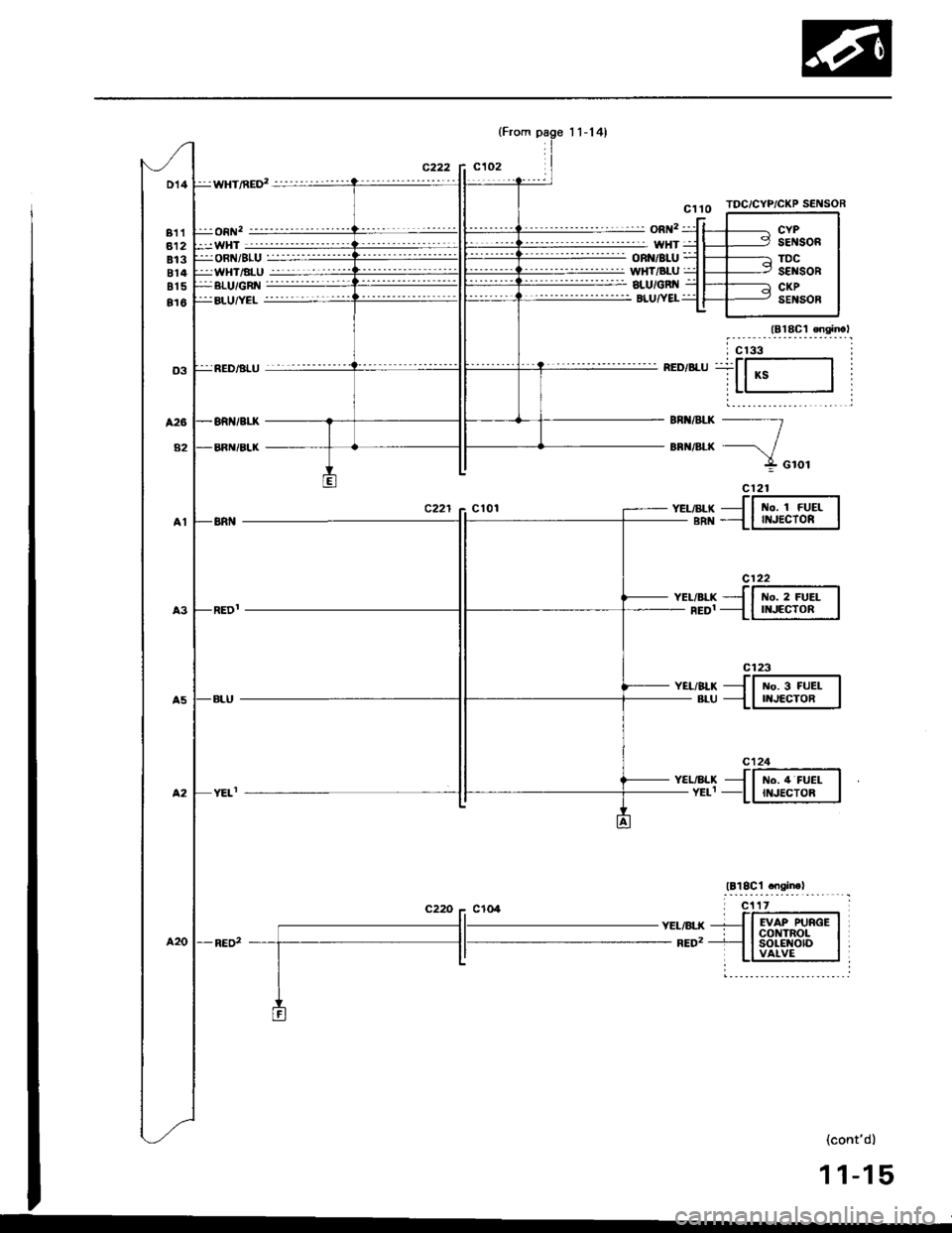
D14
811812813814815
816
:wHT/nED' -'-'--''''-''-'
:j:on 2-"''''-' '- -----
:-WHT--------'-''''-''''
TDC/CYP/CKP SENSOR
c122
t{o. 2 FUELII{JECTOR
c123
No. 3 FUELNJECTOR
c124
t{o. 4 FUELII{JECTOR
:ji oRNi sLU =::::i-:jjjjjjj:ji WHT/ALU jjji-::-:-:::i:jj
YEL/ALXYELI
YEL/BLK- RED2
(cont'd)
11-15
KS
t{o. 1 FUEIII{JECTOR
EVAP PURGEcot{TRoLsoLE {otDVAIVE
Page 224 of 1413
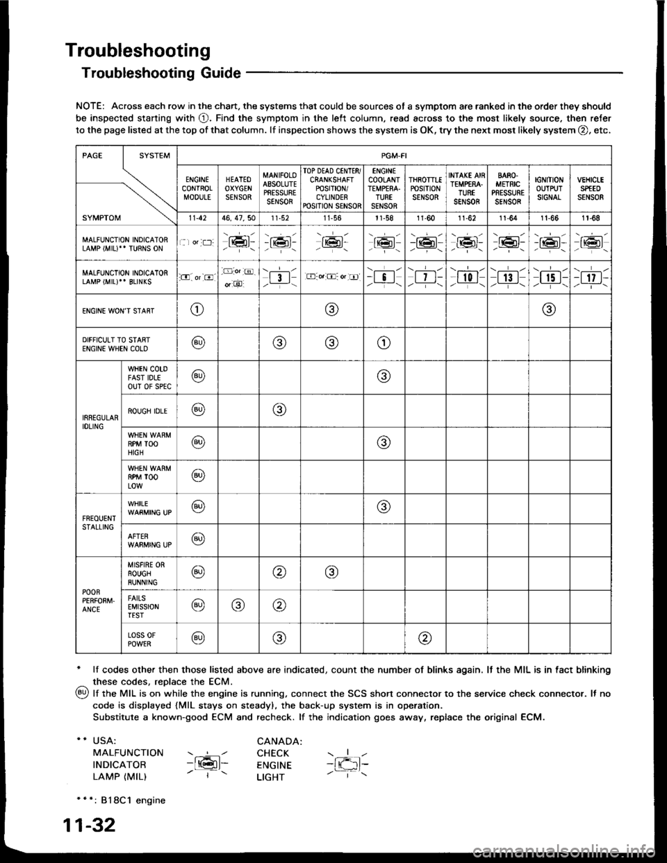
Troubleshooting
Troubleshooting Guide
NOTE: Across each row in the chart. the systems that could be sources of a symptom are ranked in the order they should
be inspected staning with O. Find the symptom in the left column, read across to the most likely source. then refer
to the page listed at the top of that column. lf inspection shows the system is OK, try the next mosr likely system O, etc,
* lf codes other then those listed above are indicated, count the number of blinks again. It the MIL is in fact blinking
^ these codes, replace the ECM.
qy, lf the MIL is on while the engine is running. connect the SCS shon connector to the service check connector. It no
code is displayed {MlL stays on steady), the back-up system is in operation.
Substitute a known-good ECM and recheck. lf the indication goes away, replace the original ECM.
USA:
MALFUNCTION
INDICATOR
LAMP {MIL)
CANADA: ----l CHECK-ltGl- ENGTNE- | - LTGHT
- { -1t-
* * *: 818C1 engine
1-32
SYMPTOM
PGM.FI
ENGINECONTROLMOOULE
HEATEOOXYGENSENSOR
MANIFOLOAESOLUTEPRESSURESENSOR
TOP DEAD CINTTR/CRANKSHAFTPOSTT|ON/CYLINDERPOSITION SENSOR
ENGINECOOLANTTEMPfRA.TURTSENSOR
THROTTTEPOStTtONSENSOR
INfAKE AIRTEMP€RA.TUREsar,rs0R
BARO.METRICPRESSURESENSOR
IGNITIONOUTPUTSIGNAL
vEHtct-ESPfEDSENSOR
11.4246, 47,5011-56l1-581l-6011-6211-641t-661r-68
MALFUNCTION INOICATORLAMP (MIU" TURNS ON1 lor:t:]:lrmr:- i;:i'-tK3t-16l-16l'-\-16l/-----\
-r:+r-
-{"Pr:-o_-16l-.z-\r6t/_-\
MALFUNCTION INOICATORLAMP (MIL)'' BLINKS:O. or-8.-D:o.:@.
o, O'l3l/__-\.E-o.:O: or tr]--i !l/ -i-\| 7 t-/__-\
--l-l-l r0 I/----\| 13 |z_---\
\.--r--l
I r5 t-/.---\-t 17 t-/-]-\
ENGINE WON'T STAffTo@@
DIFFICULT TO STARTENGIN€ WHEN COLO@@(9)o
IRREGULARIDLING
WHEN COTDFAST IDLEouT 0f sPtc@@
ROUGH IDLE@o
RPM TOOHIGH@@
RPM TOOLOW@
FREOUENTSTALLING
WHILE@@
AFTER@
POOnPERFOEM.ANCE
MISFIRE ORROUGHRUNNING@@@
FAITSEMISSIONTEST@@@
Loss 0FPOWER@@@
Page 228 of 1413
Troubleshooting
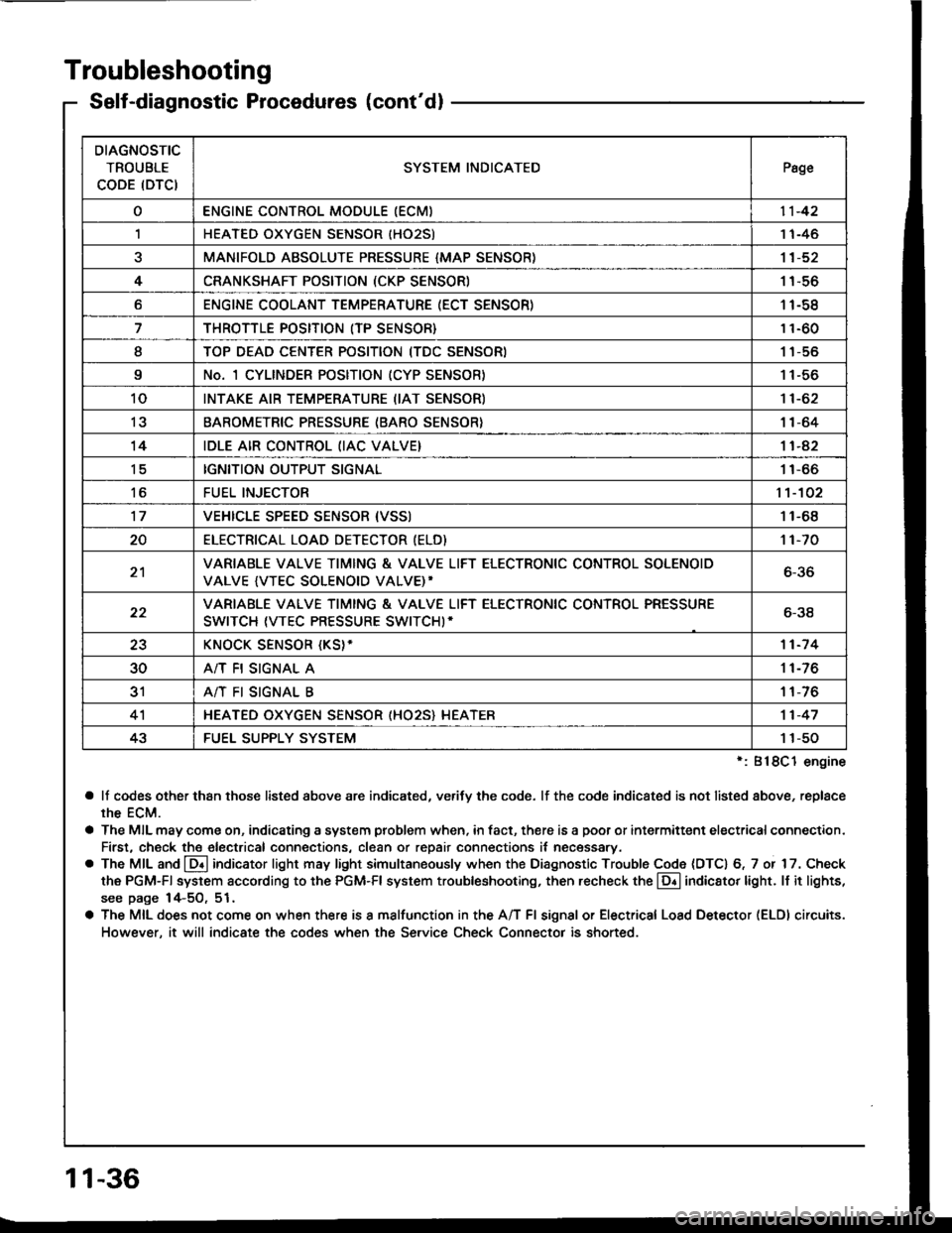
Self-diagnostic Procedures (cont'dl
':818C1 engine
a lf codes other than those listed above are indicated, verifv the code. lf the code indicated is not listed above, replace
rhe ECM.
a The MIL may come on, indicating a system problem when, in fact, there is a poor or intermittent electricalconnection.
First, check the electrical connections, clean or repair connections it necessary.
o The MIL and @ indicator light may light simultaneously when the Diagnostic Trouble Code (DTC) 6, 7 or 17. Check
the PGM-Fl system according to the PGM-Fl system troubleshooting, then recheck the l!! indicator light. ll it lights,
see page 14-5O, 51.
a The MIL does not come on when there is a malfunction in the A/T Fl signal or Electrical Load Detector (ELDI circuits.
However, it will indicate the codes when the Service Check Connector is shorted.
DIAGNOSTIC
TROUBLE
CODE (DTCISYSTEM INDICATEDPsge
oENGINE CONTROL MODULE IECM)11-42
,lHEATED OXYGEN SENSOR IHO25)1 1-46
aMANIFOLD ABSOLUTE PRESSURE {MAP SENSOR)11-52
4CRANKSHAFT POSITION (CKP SENSOR)1 1-56
oENGINE COOLANT TEMPERATURE (ECT SENSOR)11-58
THROTTLE POSITION (TP SENSOR}11-60
ITOP DEAD CENTER POSITION (TDC SENSORI1 1-56
9No. 1 CYLINDER POSITION (CYP SENSOR)1 1-56
10INTAKE AIR TEMPERATURE (IAT SENSOR)11-62
13BAROMETRIC PRESSURE (BARO SENSOR}1|-64
14IDLE AIR CONTROL (IAC VALVE}11-42
tcIGNITION OUTPUT SIGNAL11-66
toFUEL INJECTOR1't-102
17VEHICLE SPEED SENSOR {VSSI11-68
20ELECTRICAT LOAD DETECTOR (ELD)'t 1-70
21VARIABLE VALVE TIMING & VALVE LIFT ELECTRONIC CONTROL SOLENOID
VALVE {VTEC SOLENOID VALVE)'6-36
22VARIABLE VALVE TIMING & VALVE LIFT ELECTRONIC CONTROL PRESSURE
SWITCH (VTEC PRESSURE SWITCHI-6-38
23KNOCK SENSOR {KS}-11-7 4
30A/T FI SIGNAL A11-76
3'rA/T FI SIGNAL B1 1-76
4'lHEATED OXYGEN SENSOR (HO25} HEATER11-47
43FUEL SUPPLY SYSTEM1 1-50
11-36
Page 232 of 1413
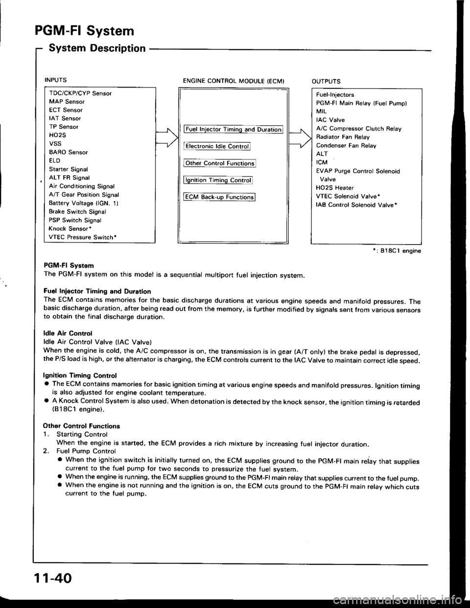
PGM-FI System
System Description
ENGINE CONTROL MODULE (ECMIOUTPUTS
PGM-Fl System
The PGM-Fl system on this model is a sequential multipon fuel injection system,
Fuol Iniector Timing and Duration
The ECM contains memories tor the basic discharge durations at various engine speeds and manifold pressures. Thebasic discharge duration, after being read out from the memory, is turther modilied by signals sent from vanous sensofsto obtain the final discharge duration.
ldle Air Control
ldle Air Control Valve (lAC Vatve)
When the engine is cold, the A/C compressor is on, the transmission is in gear (A/T only) the brake pedal is depressed,the P/S load is high, or the alternalor is charging, the ECM controls current to the IAC Valve to maintain correct idle soeed.
lgnition Timing Controla The ECM contains mamories for basic ignition timing at various engine speeds and manifold pressures. lgnition timingis also adjusted for engine coolant temperature.a A Knock Control System is also used. when detonation is detected by the knock sensof. the ignition timing is retarded(B18Cl engine).
Other Control Functions
1. Starting Control
When the engine is started. the ECM provides a rich mixture by increasing fuel injector duration.2. Fuel Pump Control
a When the ignition switch is initially turned on, the ECM supplies ground to the PGM-Fl main relay that suppliescurrent to the fuel pump tor two seconds to pressurize the tuel system.a When the engine is running, the ECM supplies gfound to the PGM-Fl main relay that supplies current to the fuel pump.a When the engine is not running and the ignition is on, the ECM cuts ground to the PGM-FI main relav which cutscurrent to the fuel pump.
TDC/CKP/CYP Sensor
MAP Senso.
ECT Sensor
IAT Sensor
TP Sensor
HO2S
vss
BARO Sensor
ELD
Starter Signal
ALT FR Signal
Air Conditioning Signal
A/T Gear Position Signal
Battery Voltage {lcN. 1)
Brake Switch Signal
PSP Switch Signal
Knock Sensor'
VTEC Pressure Switchr
Fuel-lnjectors
PGM-FI Main Relay (Fuel Pump)
MIL
IAC Valve
A/C Compressor Clutch Relay
Radiator Fan Relav
Condenser Fan Relav
ALT
rcM
EVAP Purge Control Solenoid
HO2S Heater
VTEC Solenoid Valve'
IAB Control Solenoid Valve*
lFuet tnjector Timing and Duration]
I Electr..l"ldle Contr;il
Fit'e' contr; Funcrfit
l6tio; Ttntrlg c..trol
tEcM aack-,rp Functiorlsl
': 818C 1 €ngine
11-40
Page 233 of 1413
3. Fuel Cut-oft Control
a During deceleration with the throttle valve closed, current to the {uel injectors is cut otJ to improve fuel economy
at speeds over tollowing rpm:
. 8188l engine: 91O tpm (Canada model: 1,O50 rpm)
. 818C1 engine: 95O tpm (Canada model: l,O5O rpm)
a Fuel cut-olf action also takes place when engine speed exceeds, 7,O0O rpm {81 8B1 engine), 8,1O0 rpm (B 18Cl
engine), regardless oI the position of the throttle valve, to protect the engine from ovet-revving.
A/C Compressor Clutch Relay
When the ECM receives a domand for cooling trom the air conditioning system, it del8ys the compressor from being
enetgized, and enriches the mixture to assure smooth transition to the A/C mode.
Evaporative Emission (EVAP) Purge Control Solenoid Valve
When the engine coolant tempersture is below 163oF {73"C), the ECM supplies a ground to the EVAP pu.ge control
solenoid valve which cuts vacuum to the EVAP purge control diaphragm valve.
Intake Air Bypsss (lAB) Control Sol€noid Valve
When the engine rpm is below 5,750 rpm, the IAB control solenoid valve is activated by a signal from the ECM,
intske air flows through the long intake path, then high torque is delivered. At spaeds highe. than 5,750 rpm, the
solenoid valve is deactivated by the ECM, and intake air flows through the short intake path in order to reduce the
resistance in airflow.
ECM fail-safe/bEck-up Functions
1. Fail-sate Function
When an abnormality occurs in a signal from a sensor, the ECM ignores that signal and assumes a pre-progtammed
value tor that sensor that allows the engine to continue to run.
Back-uD Function
When an abnormalitv occurs in the ECM itself, the fuel iniectors are controlled by a back-up citcuit independent of
the system in order to permit minimal driving.
Self-diagnosis Function IMaltunction Indicator Lamp {MlL)1
Wh6n an abnormality occurs in a signal from a sensor, the ECM supplies ground for the MIL and stores the code
in erasable memory. When the ignition is initially turned on, the ECM supplies ground tor the MIL tor two seconds
to check the MIL bulb condition.
Two Trio Detection Method
To prevent tals€ indications, th€ Two Trip Dstection Method is used for the HO2S and fuel metering-related self-
diagnostic tunctions. When an abnormslity occurs, the ECM stores it in its memo.y. Wh€n the ssme sbnormality
recurs alter the ignition switch is turned OFF and ON ag8in, the ECM informs the driver by lighting the MlL.
However, to ease troubleshooting, this function is canc€ll€d when you short the service check connector. The MIL
will then blink immedistelv when an abnormality occurs.
4.
6.
2
4.
11-41
Page 235 of 1413

Th. ll.lfunction Indicltor Lamp
lMlll at!y3 on o. cornaa on alt6ltwo aacond!.
Connect the SCS short connectorto th6 sorvice check connector(see page 11-34).
Turn the ignition switch ON.
Go to iolfdiagnostic Proceduros(se€ pago 11-34).Does the MIL indicate anv Oi-agnostic Trouble Code (DTC)?
Romove th€ SCS shon connectorlrom the service ch€ck connector.
Turn the ignition switch OFF.
Try to start the engine.
Connect the test harness betweenthe ECM and connectors (see
page 11-37).
Turn the ignition switch ON.
Measure voltage botween D4 (+ )terminal and D22 { - ) terminal.
connect the SCS shonconnector to servlcecheck connector.ls there approx. 5 V?
Ropair shon to body g.ound inBRN/WHT wire betwoon th6 ECMlD4) end sorvlco chock connocto?.Measure voltage be_tween D4 {+} terminaland body ground.
- R6pair open in BRN/WHT witobotwoon EcM lD4) and s6rv-ice chock connactor.- Repoir opon in BLK wiro bo-twoon 36rvi@ chock connectoaand G4Ol.
ls there approx. 5 V?
InsDoct ECU {ECM) 115 A) tuse inth6 undeFhood luse/relav box.
- Rsolaco ECU {ECM} (15 Allus€.- R6pair shon in YEL/WHT wilobotw6on ECU lEcMl 115 A)fuso and PGM-FI main rolay.
Remove the scs shortConnector from theservice check con-nector.
ls the luss OK?
NOTE:
a When there is no code stored, the MIL willstay on if the service check con-
nector is shorted.
a tf this svmotom is intermittent, check for:
- A loose ECM fuse (15A) in the under-hood tuse/relay box
- A loose No. 24 fuse (ACG) (ALT) ( 1 5A: B1 8B 1 engine, 2OA: B18C 1 en-
gine) in the under-dash fuse/relay box- An intermittent short in the BRN/WHT wire between the ECM (D4) and
the service check connector- An intermittent oDen in the BLK wire between the service check con-
nector and G4O1- An intermittent shon in the GRN/ORN wire between the ECM (A 13) and
the gauge assembly.- An intermittent short in the YELMHT wire between the ECM (D19) and
the MAP sensor- An intermittent short in the YEL/BLU wire between the ECM (D20) and
the TP sensor
o ooooo ooo ooo o loooooooo liii:$A$.Ps,l o oo ooo ooooo
o oooo ooo o o ooo I oooooooooooooooooo
D4 (+)
l"oo,o'.
D22 t-l
uu,l
'NOTE: After repair, disconnect the SCS ShortConnsctor, test drive the car, and recheckthe MIL
lor a code.
(cont'd)
(To page 1 'l -44)lTo page 1 1-44)
11-43
Page 236 of 1413

(From page 1 1-43)
Inspect the No. 24ACG {ALT) (lG)(15 A: 81881 engine, 2OA:818C1 enginel fuse in the under-dash fuse/relav box.
- R.pllr .hon in BLK|rEL wlr6batr.v€qr undariair luro/Fbybox lnd FGM-FI m.in .obv.- noebco lto. 24 ACG {lG) nLT)(15 A: 81881 ongin., 2OA:Bl8Cl onein.l tu!6.
ls the fuse OK?
Turn the ignition switch ON.
Disconnect the 3P connector oteach sensor one al a time:. MAP sensor. TP sensor
Rcplaoo thg lgnlor that caur6dth. llght to Oo out.Does the MIL remain ON?
Turn the ignition switch OFF.
connect the test harness.Disconnect the "D" connectorfrom th€ ECM only, not the mainwire harness (see page 11-37).
Check tor continuity betweenbody ground and D19, O2O ter-minals,
- Bapai? rhod ro body g.ound inYEL/WHT wi.e boiwoon ECM(Dl9) .nd MAP ..n3or.- R.p!k shon to body ground inYEL/BLU wire b.lwo6n ECM(O2Ol .nd TP 3on!or.
Reconnect all tho sensor con-necrors,Reconnect the "D" connector torhe ECM.
Turn the ignition switch ON.
{To page 11-45}
System
Control Module (ECMI (cont'dl
PGM-FI
Engine
Dt9I
I oooooooooo ooo I oooooooo I omoool o oooooooooo | |I ooooooooooooo I oooooooo 1o('oe(lo I ooooooooooo | |-lD2O I
\-.J
Continuity?
(From page 11-43)
Disconnect "A" con-nector from the ECM.
Subrtltute r knowngood ECM.nd rochock. ll lymptom/indics-tlon g@a rw!y, rephco tho origi-n.l ECM.
ls the MIL ON?
Ropair short to bodygiound in GRN/ORNwir6 botwoon tho ECMlA131 6nd MlL.
11-44