ACURA INTEGRA 1994 Service Repair Manual
INTEGRA 1994
ACURA
ACURA
https://www.carmanualsonline.info/img/32/56982/w960_56982-0.png
ACURA INTEGRA 1994 Service Repair Manual
Trending: oil filter, wheelbase, fog light, diagram, battery, power steering, driver seat adjustment
Page 1111 of 1413
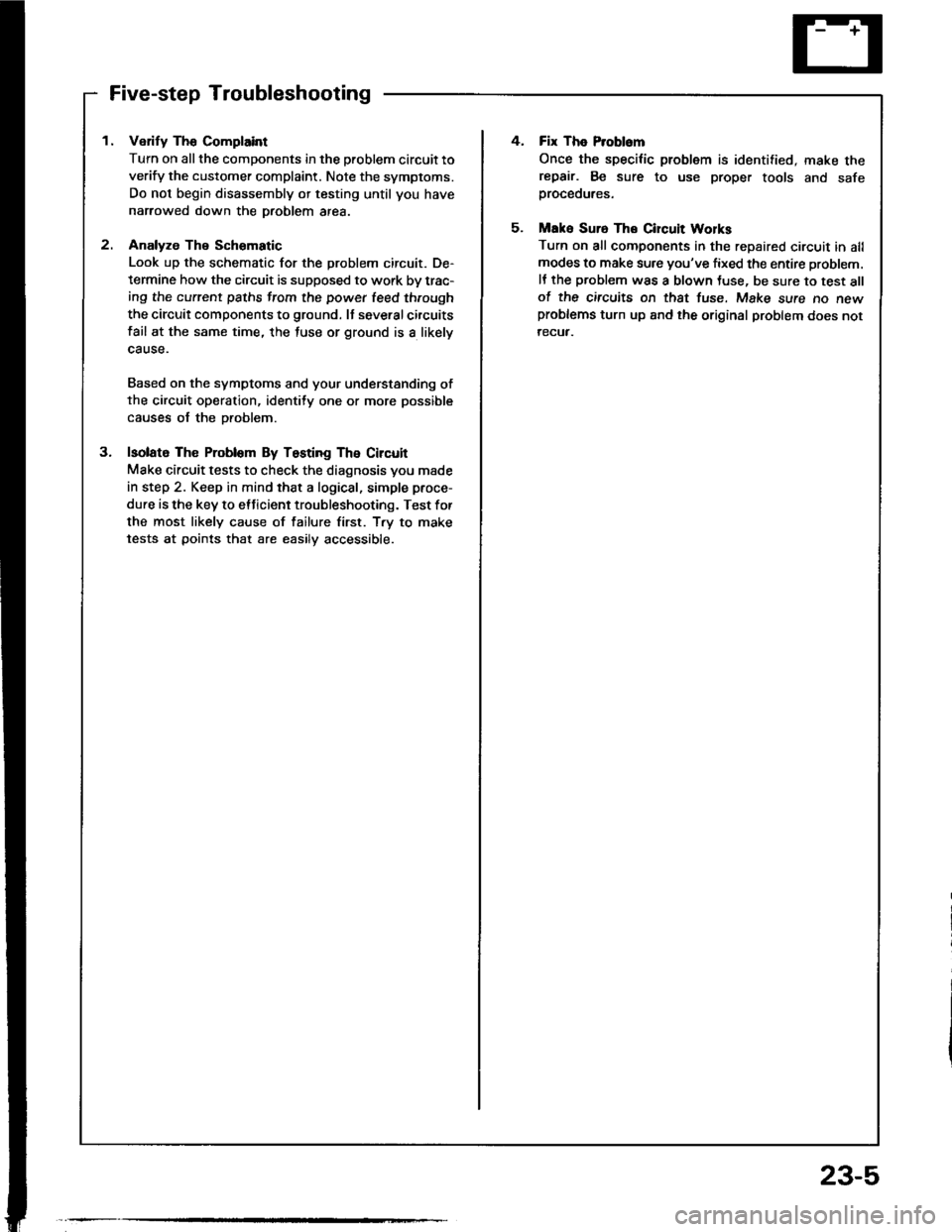
Five-step Troubleshooting
1. Verify The Complaint
Turn on all the components in the problem circuit to
verify the customer complaint. Note the symptoms.
Do not begin disassembly or testing until you have
narrowed down the Droblem area.
2. Analyze The Schomatic
Look up the schematic for the problem circuit. De-
termine how the circuit is supposed to work by trac-
ing the current paths from the power leed through
the circuit components to ground. It severalcircuits
fail at the same time, the luse or ground is a likely
cause.
Based on the symptoms and your understanding of
the circuit operation, identity one or more possible
causes of the Droblem.
3. lsolato The Problom By Testing The Circuit
Make circuit tests to check the diagnosis you made
in step 2. Keep in mind that a logical, simple proce-
dure is the key to etticient troubleshooting. Test for
the most likely cause of failure first. T.y to make
tests at points that are easilv accessible.
4. Fix The Problem
Once the specilic problem is identified, make therepair. Be sure to use proper tools and safeproceoures.
5. Mak6 Suro The Circuit Wolks
Turn on all components in the repaired circuit in allmodes to make sure you've fixed the entire problem.
It the problem was a blown Juse, be sure to test allof the circuits on thst tuse. Make sure no newproblems turn up and the original problem does not
recuf.
23-5
Page 1112 of 1413
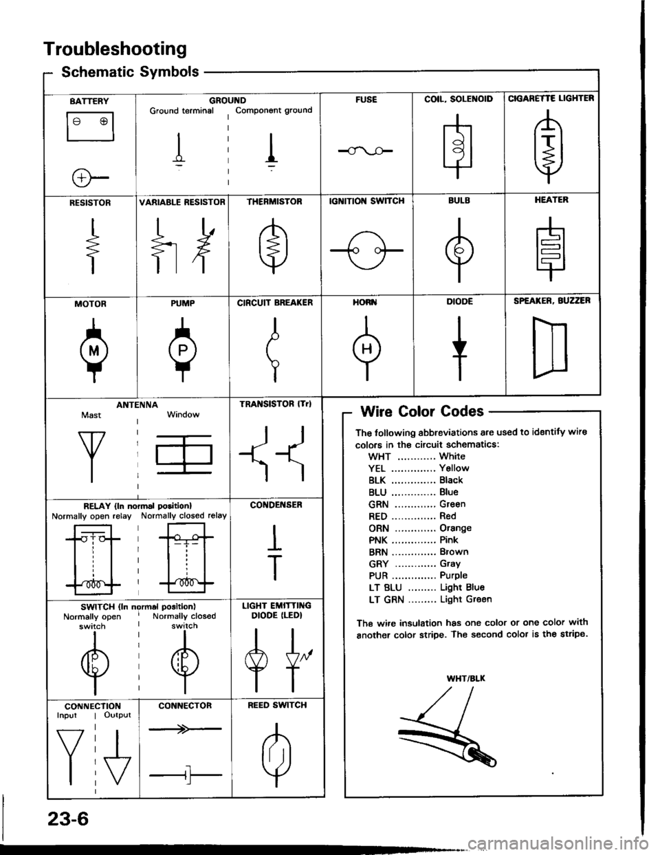
Troubleshooting
Schematic Symbolsym
BATTERY
le @l
ll
e-
GROIGround terminal
I
,ltDComponont ground
I
FUSECOIL, SOLENOID
H
CIGANETTE LIGHTER
A
t+j
RESISTOR
+
VARIABLE RESISTOR
ilH
THERMISTOR
e
tcNtTtol{ swTcH
-1o oF
BULB
e
HEATER
H
MOTOR
a
PUMP
0
CIRCUIT BREA(ER
I
T
HORI'
+
DIODE
+
SPEATER, BUZZER
D
Mast
Y
ANTIINNATRA SISTOR lTrl
II
Wire Golor Codes
The tollowing abbreviations are used to identity wire
colors in th€ circuit schematics:
wHT ............ White
YEL .............. Y6llow
BLK .............. Black
BLU .............. Blue
GRN ............. Green
RED.............. Red
ORN ............. Orange
PNK .............. Pink
BRN .............. Brown
GRY ............. Gray
PUR .............. Purple
LT BLU ......... Light Blue
LT GRN ......... Light Gr€en
The wi.e insulation has one color or one color with
another color stripe. The s€cond color is the stripe.
WHT/ALK
,/t,/l./l--
R
RELAY {ln noNormally open relayrmal poritionl
Normally closed relay
*Gt-i- |
lll
l'*^f
CO'IDENSER
I
T
SWITCH (ln ngrmal position)
Normally open ' Normally closodswitch I switch
til
@@
lil
LIGHT EMITTINGDIODE (LEDI
A[,
TT
CONNEInpur
f7
I
CTIONOutput
I\/
CONNECTON
--+>-
tl'l
BEED SWITCH
A
lril
Y
23-6
Page 1113 of 1413
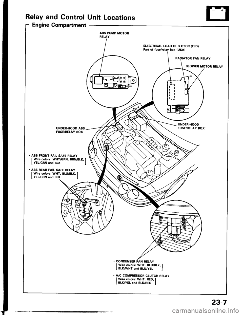
Relay and Control Unit Locations
Engine Compartment
ABS PUMP MOTORRELAY
ELECTRICAL LOAD DETECTOR (ELD)
UNDER.HOODFUSE/RELAY BOXUNOER-HOOD ABSFUSE/BELAY BOX
. ABS FRONT FAIL SAFE RELAY
I Wirc colors: WHT/GRN, BRN/BLK, IIYEL/GRN snd BLK I
. ABS REAR FAIL SAFE RELAY
I Wire colors: WHT, BLU/BLK, II YEL/GRN and BLK I
. CONDENSER FAN RELAY
I Wi]o colors: WHT, BLUi BLK, II BLKMHT and 8LU/YEL I
. A/C COMPRESSOR CLUTCH RELAY
I Wiro colors: WHT, RED, II BLK/YEL and BLK/RED I
23-7
Page 1114 of 1413
Relay and Control Unit Locations
Dashboard and Door
CRUISE CONTROL UNIT
PGM-FIMAIN RELAY
STARTER CUT RELAY IMIT)
I wir. colo]s: BLKMHT, BLU/BLK II BLKMHT ANd BLK/RED I
Wirs colors:WHT,GBN/BLK,GRN 6nd BLK
MOONROOF RELAYREAR wlNDOW DEFOGGERFELAY
I Wiro colo6: II BLKA'EL, BLK/GBN, I
I BLUffEL 8nd BLK^^THT I
POWER WINDOWRELAY
IIORN RELAY
J wi.o color3: WHT/GRN, BLx,l
I BLU/GBN, and BLU/RED I
INTEGRATEOCONTROL UNIT
TURN SIGI{AL/HAZARDRELAY UNDEB-OASHFUSE/RELAY 8OX
23-8
Page 1115 of 1413
I
I
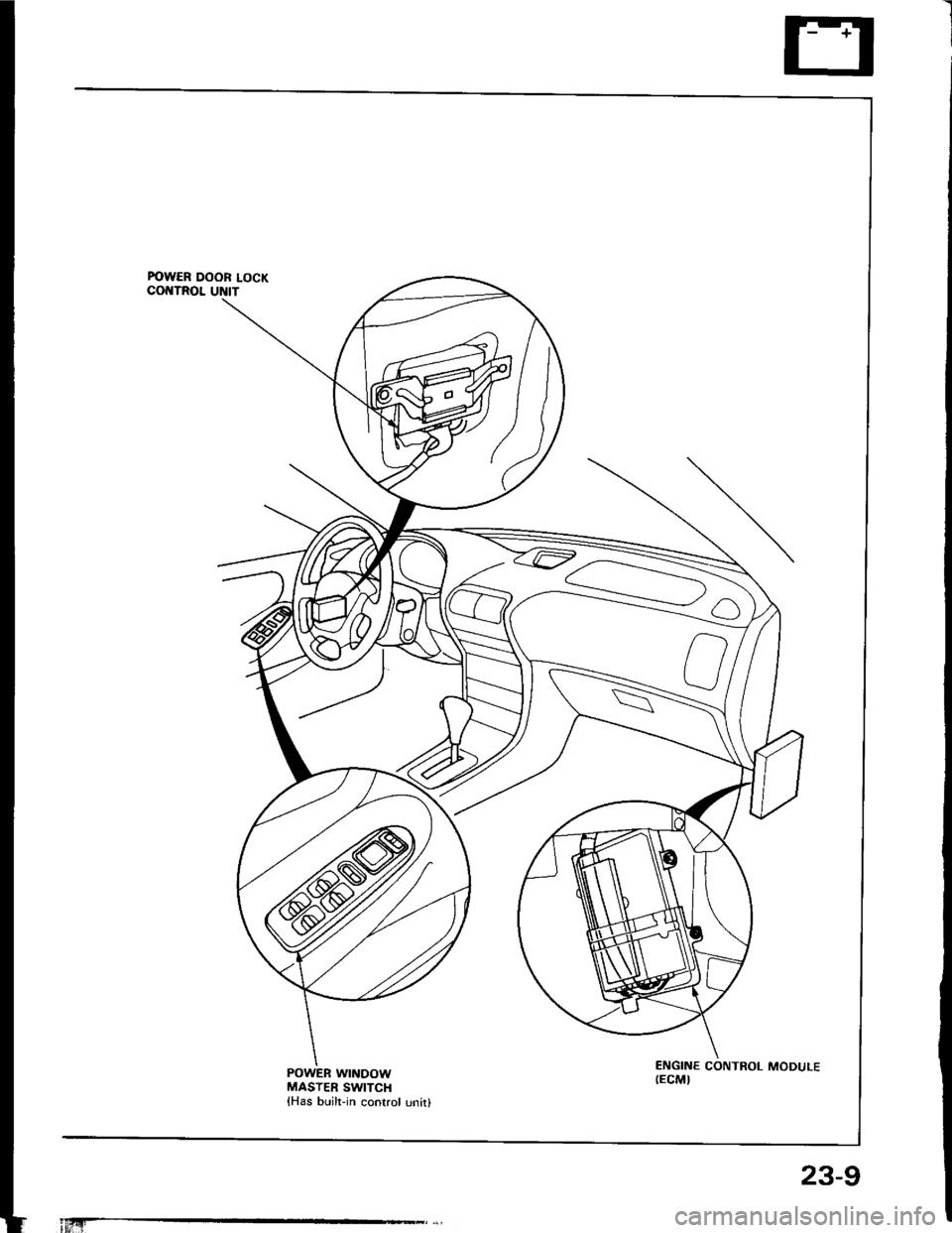
POWER DOOR LOCKCOI{TROL UNIT
ENGINE CONTROL MODULE(ECM}
ii.11r'
23-9
Page 1116 of 1413
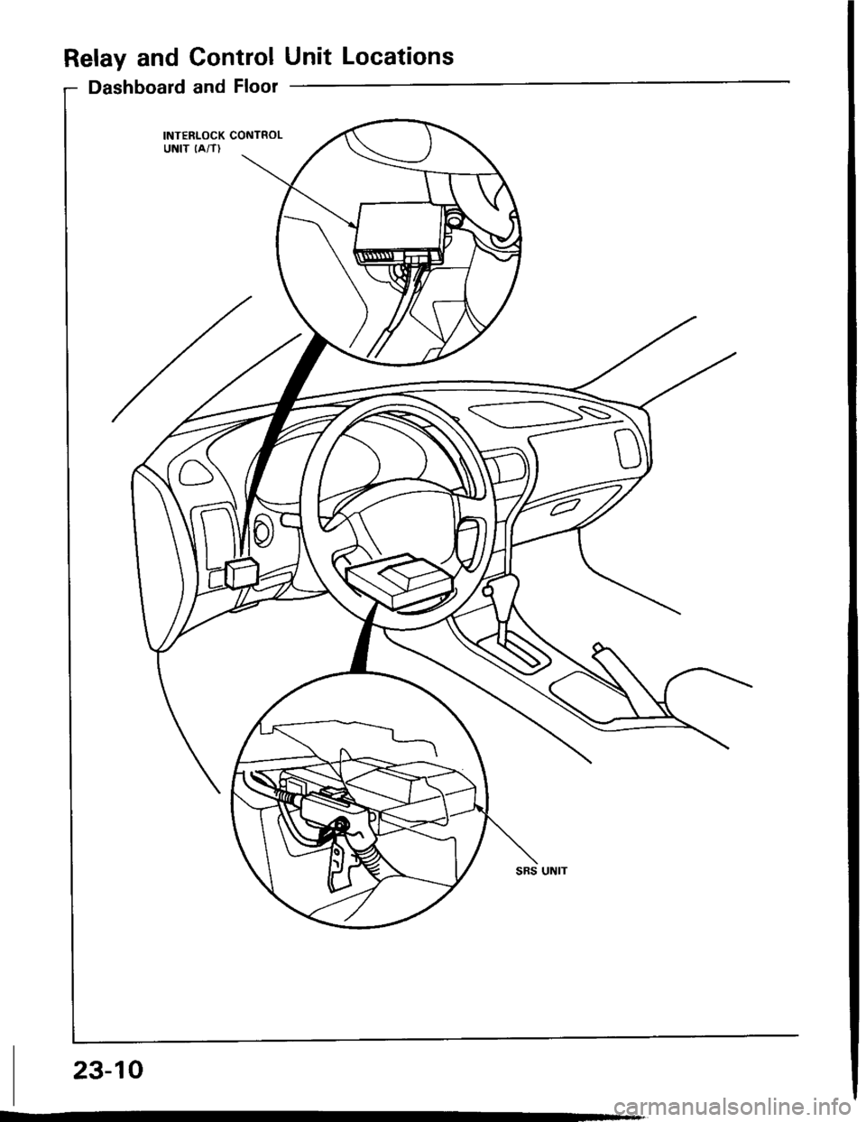
Relay and Control Unit Locations
Dashboard and Floor
INT€RLOCK CONTROLUNIT IA/T)
G
23-10
Page 1117 of 1413
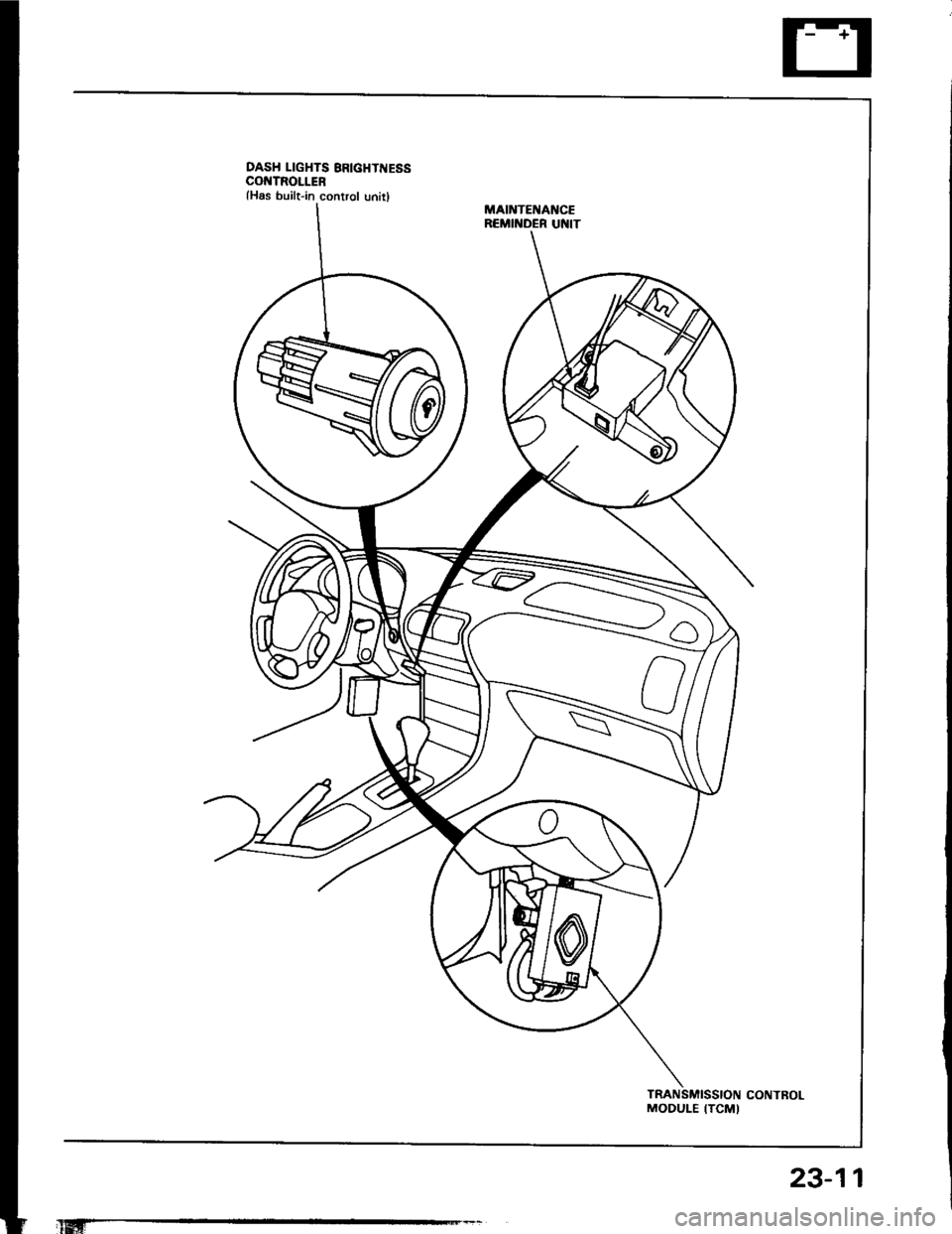
MAINTENANCEREMINOER UNIT
TRANSMISSION CONTBOLMODULE ITCMI
lEl
23-11
Page 1118 of 1413
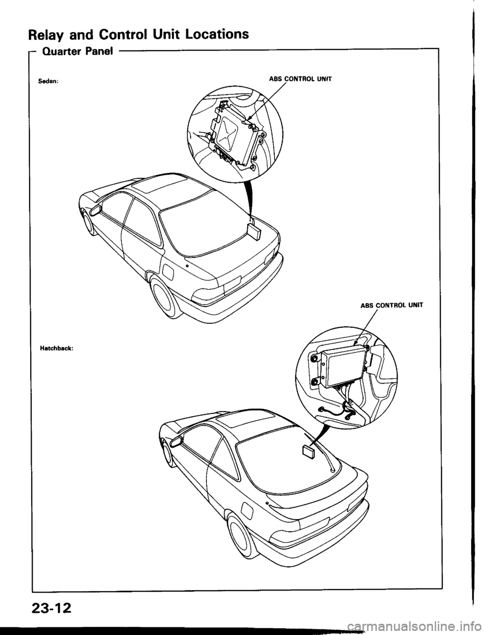
Relay and Gontrol Unit Locations
Ouarter Panel
ABS CONTROL UNIT
23-12
Page 1119 of 1413
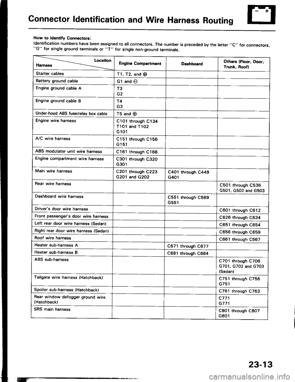
Connector ldentification and Wire Harness Routing
How to ldentity ConnoctolS:
ldentification numbers have been assigned to all connectors. The number is preceded by the letter ,,C,, for connecrors,"G" for single ground terminals ot "f" hr single non-ground terminals.
Location
HamessEngino CompartmontDarhboardOthors (Floor, Door,
Trunk, Rootl
Starter cablesT1, T2, and (E
Battery ground cableG1 and O
Engine ground cable AT3
Engine ground cable BT4
G3
Under-hood ABS fuse/relav box cableT5 and (D
Engine wire harnessC101 through C134
Tl Ol and T102
G 101
A/C wire harnessCl 5'l through C156
G151
ABS modulator unit wir€ harnessC161 through C168
Engine companment wire ha.nessC3O'l through C32O
G301
Main wire hatnessC2O1 through C223
G2Ol and G2O2
C4O1 through C449
G401
Rear wire harnessC501 through C536
G501, G502 and G5O3
DashboSrd wire harnessC551 through C569
G551
Driver's door wire harnessC601 through C612
Front passenger's door wire harnessC626 through C634
Left rear door wire harness (Sedan)C651 through C654
Right rear door wire harness (Sedan)C656 through C659
Roof wire harnessC661 through C667
Heater sub-harness AC671 through C677
Heater sub-hatness BC681 through C684
ABS sub-harnessC7O1 through C7O6
G7O1, G702 and G703(Sedan)
Tailgate wire harness (Hatchback)C751 through C756
Spoiler sub-ha.ness (Hatchback)C761 through C763
Rear window defogger ground wire(Hatchback)c77'l
G771
SRS main harnessC8O1 through C8O7
G801
23-13
Page 1120 of 1413
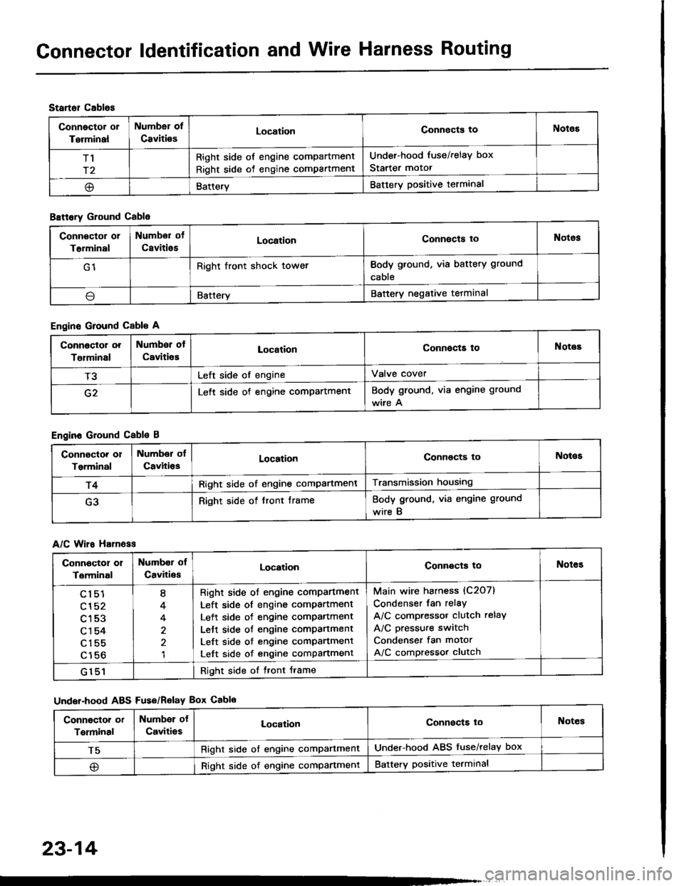
Gonnector ldentification and Wire Harness Routing
Startol cablos
Connector or
Terminal
Numbsr of
CavitiesLocationConnects toNotos
T1
r2
Right side of engine compartment
Right side of engine compartment
Under-hood fuse/relay box
Starter motor
@BatteryBattery positive terminal
B8ttory Ground Cable
Engine Ground Cable A
Engine Ground Cable B
A/C Wiro H81n6ss
Under-hood ABS Fus€/Relav Box Cablo
Conn€ctor or
T€rminal
Numbor of
CsvitiesLocationConnects toNotos
G1Right front shock towerBody ground, via battery ground
cable
\lBatteryBattery negative tetminal
Connoctor or
Tolminal
Number of
CavitiesLocationConnocta toNotes
T3Left side of engineValve cover
G2Left side of engine compartmentBody ground. via engine ground
wire A
Connoctor or
Torminal
Number ol
CavitiosLocationConnocts toNot€s
r4Right side of engine compartmentTransmission housing
G3Right side of front frameBody ground, via engine ground
wire B
Connoctor 01
Terminal
Numbor of
CavitiesLocationConnects toNotes
cl51
cl52
c153
c1 54
c155
c156
I
4
4
1
Right side ol engine comPartment
Left side of engine compartment
Left side of engine comPartment
Lett side ot engine compartment
Left side of engine comPanment
Left side of engine compartment
Main wire harness (C2O7)
Condenser fan relay
A/C compressor clutch relay
A/C pressure switch
Condenser fan motor
A/C compressor clutch
G151Right side of tront Jrame
Conngctor or
Terminal
Numbor ot
Caviti€sLocalionConnects loNotes
T5Right side of engine comPartmentUnder-hood ABS fuse/relay box
@Right side of engine compartmentBattery positive terminal
23-14
Trending: washer fluid, fuel cap release, service reset, fuses, power steering fluid, child restraint, battery


![ACURA INTEGRA 1994 Service Repair Manual Relay and Control Unit Locations
Dashboard and Door
CRUISE CONTROL UNIT
PGM-FIMAIN RELAY
STARTER CUT RELAY IMIT)
I wir. colo]s: BLKMHT, BLU/BLK II BLKMHT ANd BLK/RED I
Wirs colors:WHT,GBN/BLK,GRN 6nd ACURA INTEGRA 1994 Service Repair Manual Relay and Control Unit Locations
Dashboard and Door
CRUISE CONTROL UNIT
PGM-FIMAIN RELAY
STARTER CUT RELAY IMIT)
I wir. colo]s: BLKMHT, BLU/BLK II BLKMHT ANd BLK/RED I
Wirs colors:WHT,GBN/BLK,GRN 6nd](/img/32/56982/w960_56982-1113.png)
