oil filter ACURA INTEGRA 1994 Service Repair Manual
[x] Cancel search | Manufacturer: ACURA, Model Year: 1994, Model line: INTEGRA, Model: ACURA INTEGRA 1994Pages: 1413, PDF Size: 37.94 MB
Page 12 of 1413
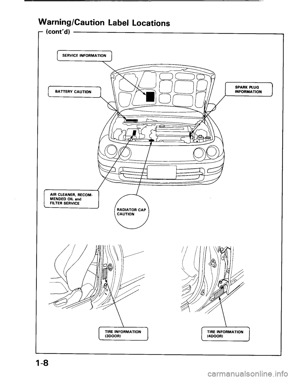
Warning/Caution Label Locations
(cont'd)
SERVICE INFORMATION
C)
SPARK PtUG
II{FORMATIONBATTERY CAUTION
AIR CLEAI{€R, RECOM-
MENDEO OIL and
FILTER SERVICE
RADIATOR CAP
CAUTIOI{
TIRE INFORMATION
{300()R)
TIRE INFORMATIOII
t4DOOR)
1-8
Page 23 of 1413
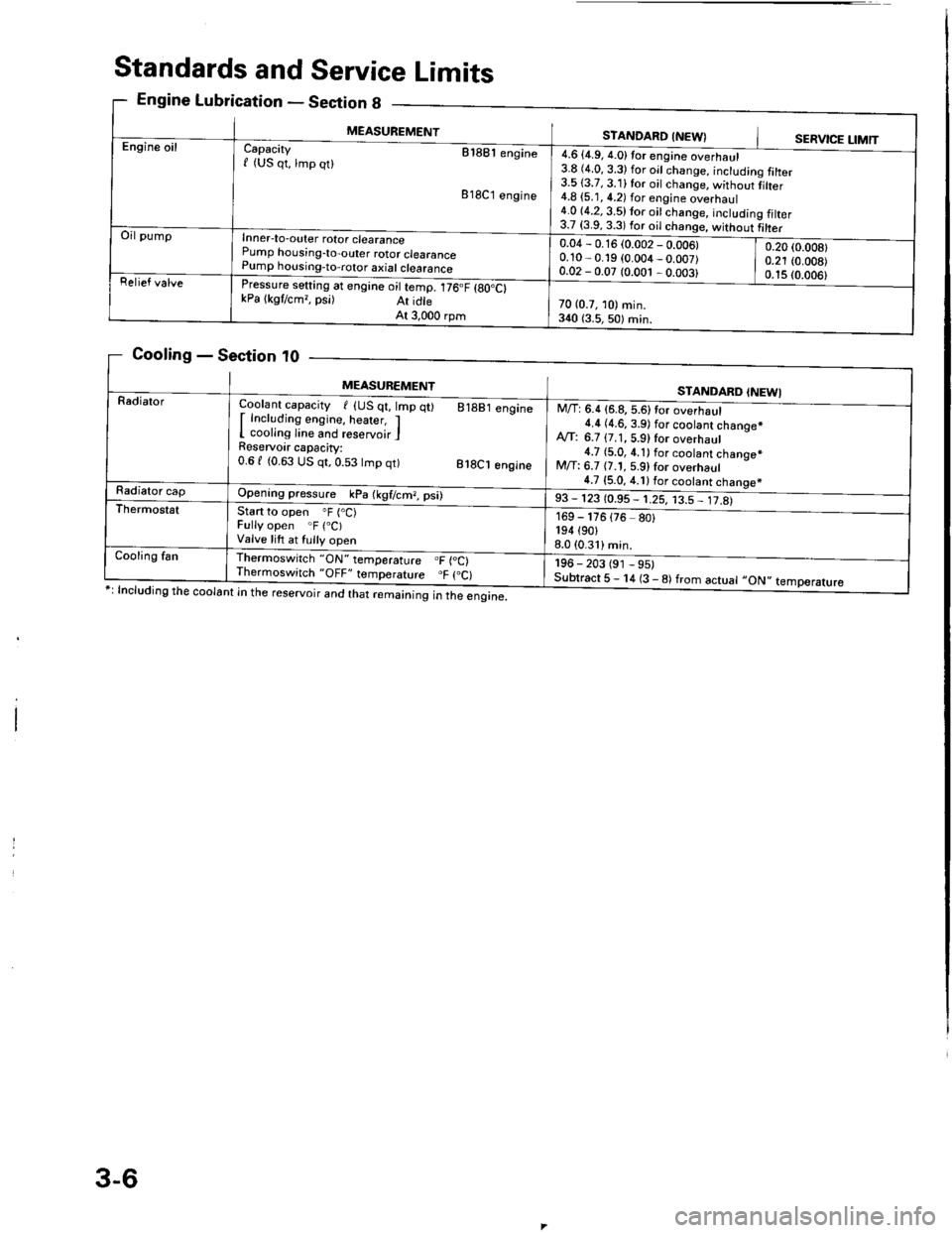
Standards and Service Limits
Engine Lubrication - Section g
Cooling - Section t0
ng the coolant in the reservoir and that remaining in the engine.
eclton u _
MEASUREMENTSTANDARD INEW}SERVICE LIMTT
g talter
tiher
g filter
Engine oilCapacity etaet engine
f (US qt, lmp qt)
818C1 engine
Inner-to-outer rotor clearance
Pump horising-to-outer rotor clearance
Pump housing-to,rotor axial clearance
rressure setting at engine oil temp. 176.F {gO.Ct
kPa lkgtcm,, psi) At idte
At 3,000 rpm
4.6 {4.9, 4.0}tor engine overhaul
3.8 (4.0, 3.3) for oil change, inctudin
3.513.7, 3.11 for oil change, without
4.8 {5.1, 4.2) for engine overhaul
4.0 (4.2, 3.5) lor oit change, includin
3.7 i3.9 3 3l fdr ^il .hi
Oil pump
0.04 - 0.16 (0.002 - 0.006)
0.10 - 0.19 (0.004 _ 0.007)
0.02 - 0.07 (0.001 , 0.003)
0.20 (0.008)
0.21 (0.008)
0.1s (0.006)
Relief valve
70 (0.7, 10) min.
3{0 {3.5,50) min.
MEASUBEMENTSTANDARD INEWI
RadialorCoolant capacity I {US qt, lmp
I Including engine, heater, I
I cooling line and reservoir I
Reservoir capacity:
0.61 (0.63 US qt,0.53 tmp qt)
q0 81881 engine
818C1 engine
Opening pressure kPa (kgf/cm?, psi)
start to open oF (.C)
Fully open .F (.C)
Valve lift at fully open
lhermoswitch "ON" temperature .F {oC)
Thermoswitch "OFF" temporature "F (.C)
M/T: 6.4 (6.8, 5.6)tor overhaul
4.4 (4.6.3.9) f6r s66lsn1gh66q.*
A,rf: 6.7 {7.1, 5.9) for overhaul
4.7 {5.0, 4.1) for coolant chanoe*
M/T: 6.7 {7.1, 5.9} for overhaul
4.7 {5.0, 4.1) for coolant chanoe*
,3 - 113 toss - trs, r3= Jt&
-
196 - 203 (91 - 95)
Subtract 5 - 14 (3 - 8) from actuat -ON',
169 - 176
194 (90,
8.0 (0.31)
{76 80}
temperature
Radiator cap
Thermostst
Cooling fan
3-6
Page 102 of 1413
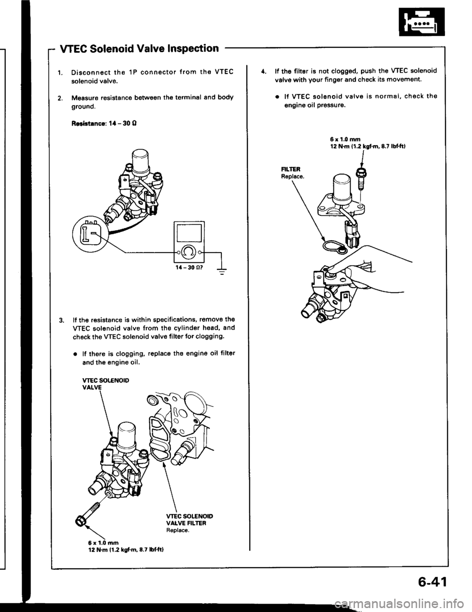
WEC Solenoid Valve Inspection
Disconnect the 1P connector trom the VTEC
solenoid valve.
M€asurs resistance between th€ terminal 8nd body
grouno.
R.3bt!nc!: 1l - 30 O
lf the resistance is within specificstions, romove the
WEC sol€noid valve from the cvlindor hsad, and
check the VTEC solenoid valve filter for clogging.
. lf there is clogging, replacs the engin€ oil filter
and the engine oil.
VTEC SOT.CNOTD
12 tTln 11.2 kg[.m,8.7 lbttt]
6-41
4. lf th6 filter is not clogged, push the VTEC solenoid
valv€ with your finger and check its movement.
. lf VTEC solsnoid valve is normal, check the
engins oil pr€ssure.
6x1.0mm
Page 167 of 1413
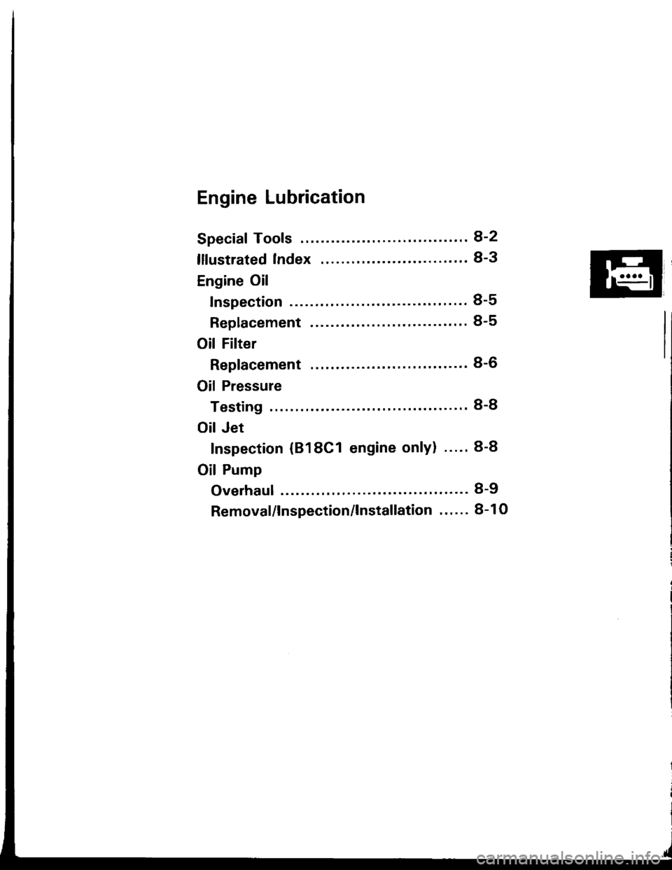
Engine Lubrication
Speciaf Tools ........ ........8-2
lllustrated Index ........ ."' 8-3
Engine Oil
Inspection ..........."'...' 8-5
Replacement ................ " ".......'.'. 8-5
Oil Filter
Replacement ...................... "....... 8-6
Oil Pressure
Testing ....' 8-8
Oil Jet
Inspection {818C1 engine only} ..... 8-8
Oil Pump
Overhaul ... 8-9
Removal/lnspection/lnstallation . . ' . . . 8- 1 O
Page 168 of 1413
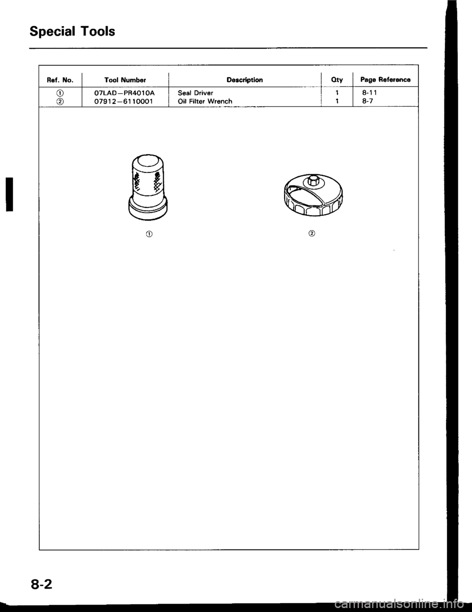
Special Tools
Rel. No. I Tool NumbelDescrlptionOty I Pago Roferenco
o
@
OTLAD _ PR4Ol OA
o791 2 -61 10001
Seal Driver
Oil Filter Wrench
8-11
8-7
o
8-2
Page 170 of 1413
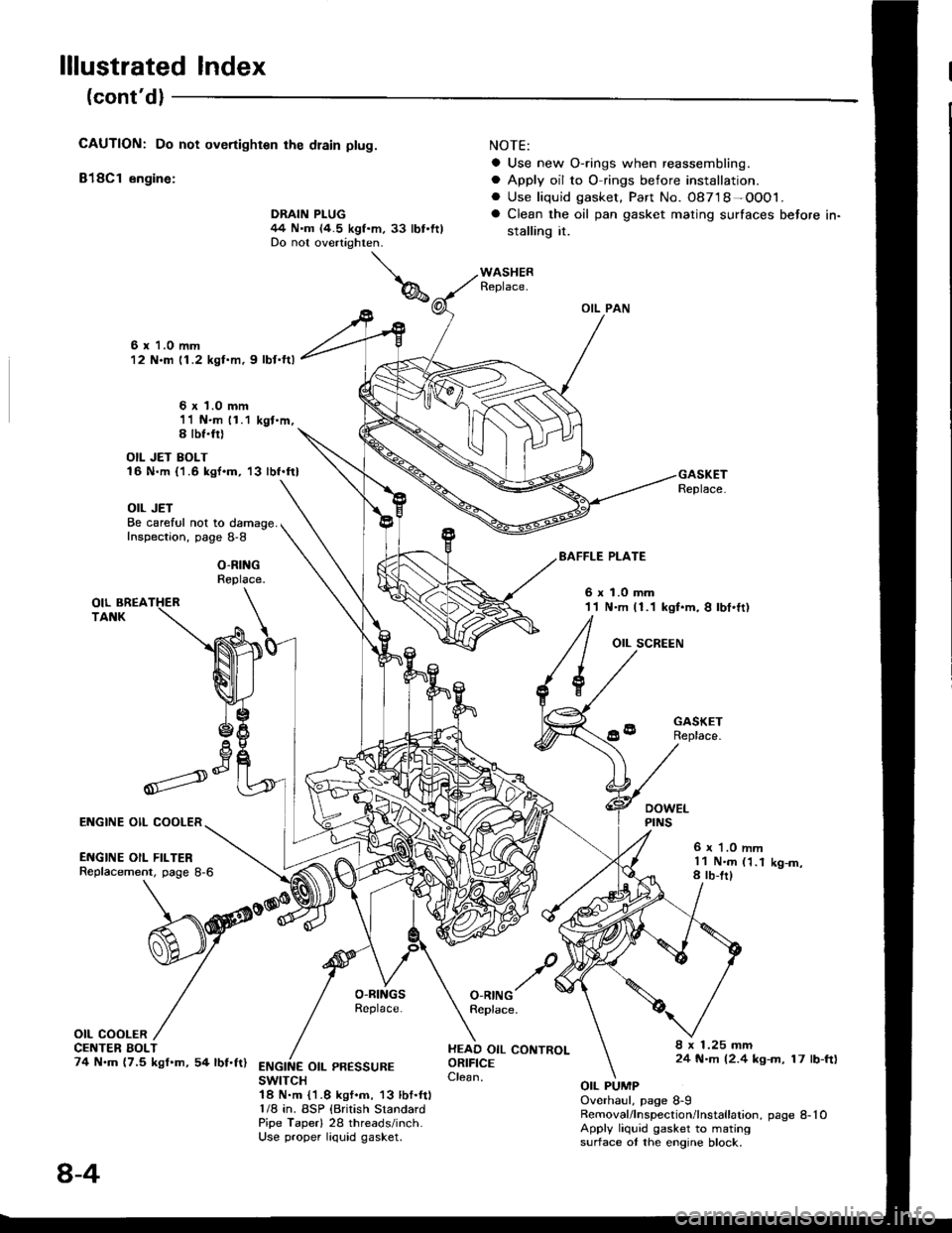
lllustrated Index
(cont'dl
CAUTION: Do not overtighten rhe dlain ptug.
818C1 engine:
NOTE:
a Use new O-rings when reassembling.
a Apply oil to O rings before installation.. Use liquid gasket. Part No. 08718-OOO1.
a Clean the oil pan gasket mating surfaces before in-
stalling it.
OIL PAN
Replace.
6 x 1.0 mm12 N.m 11.2 kgl.m, 9 lbf.ftl
6 x 1.0 mm11 N.m 11.1 kgt.m,S lbf.fil
OIL JET BOLT16 N.m {'1.6 kgf.m, '13 lbf.ft}
OIL JETBe careful not to damage.Inspection, page 8-8
O-RINGReplace.
EAFFLE PLATE
6xl.0mm11 N.m (1.1 kgt.m, I lbt.ft)
OIL SCREEN
GASKETReplace.
6 r '1.0 mml1 N.m (1.18 rb-trlK9-m,
O-RINGReplace.
HEAD OIL CONTROLORIFICEClean.
8 x 1.25 mm24 N.m (2.4 kg-m, 17 lb-ft)ENGINE OIL PR€SSUREswtTcH1A N.m {1.8 kgf.m, 13 lbf.ft)1/8 in. BSP {British StandardPipe Taperl 28 threads/inch.Use proper liquid gasket.
OIL PUMPOverhaul, page 8-9Removal/lnspection/lnstallation, page 8-10Apply liquid gasket to matingsurface ot the engine block.
Il
,--)e6V
ENGINE OIL COOLER
ENGINE OIL FILTERReplacement, page 8-6
OIL COOLERCE TER BOLT74 N.m (7,5 kgf.m, 54 lbf.ft)
DRAIN PLUG44 N.m (4.5 kgf.m, 33 lbt.ftlDo not overtighten.
8-4
Page 171 of 1413
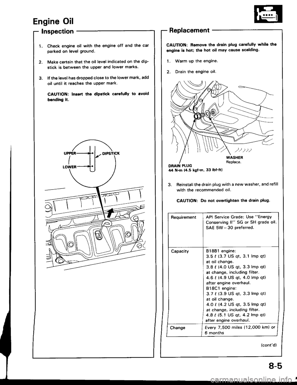
Engine Oil
lnspection
Check engine oil with the engine off and ths cal
parked on level ground,
Make cenain that the oil level indicated on the dip-
stick is between the upper and lower marks.
lf the l€vel has dropped close to the lower mark, add
oil until it reaches the upper mark.
CAUTION: Inssrt lho dipstick carotully to avoid
bending it.
3.
Replacement
CAUTION: Remova tho drain plug cal€fully whilo the
ongine is hot; the hot oil may cause scalding.
1. Warm up the engine.
2, Drain the engine oil.
3. Reinslallthe drain plug with a new washer, and refill
with the recommended oil.
CAUTION: Do not ovortighton tho drain plug.
(cont'd)
RequirementAPI Service Grade: Use "Energy
Conserving ll" SG or SH grade oil.
SAE 5W-3O Drefered.
CapacityB18B1 engine:
3.51 (3.7 US qt, 3.1 lmp qtl
at oil change.
3.8 t (4.0 US qt, 3.3 lmp qt)
at change. including filter.
4.6 I 14.9 US qt. 4.0 lmp qt)
after engine overhaul.
B18Cl engine:
3.7 f (3.9 US qt, 3.3 lmp qt)
at oil change.
4.O t 14.2 US qt, 3.5 lmp qt)
at change, including filter.
4.a I (5.1 US qt, 4.2 lmp qt)
after engine overhaul.
ChangeEvery 7,5OO miles (12,OOo km) or
6 months
8-5
Page 172 of 1413
Englne Oil
Replacement {cont'd)
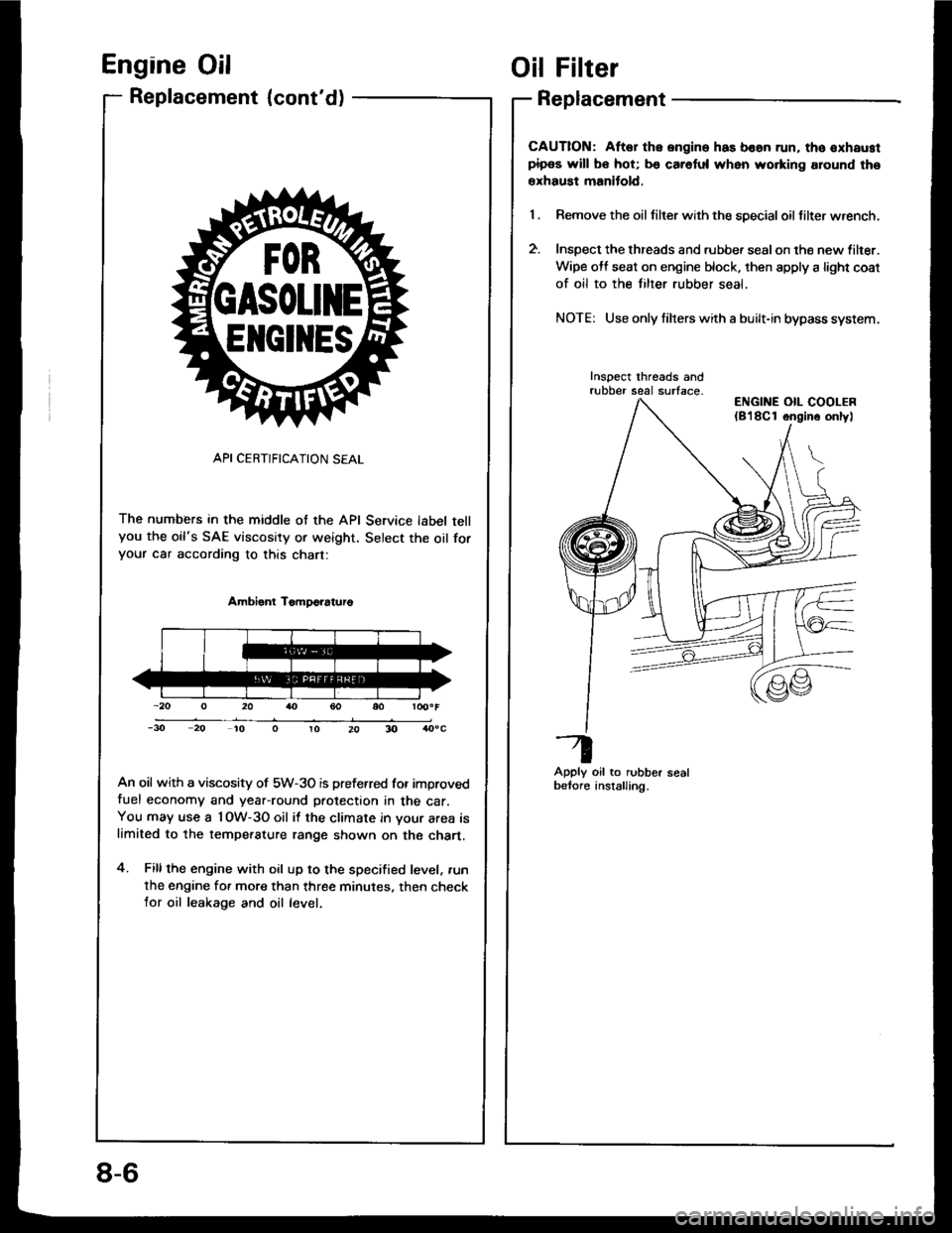
API CERTIFICATION SEAL
The numbers in the middle of the API Service label tellyou the oil's SAE viscosity or weight. Select the oil foryour car according to this chart:
Ambient TomDo?aturo
An oil with a viscosity of 5W-3O is preferred for improvedfuel economy and year-round protection in the car.You may use a l OW-3O oil it the climate in your area islimited to the tempe.ature range shown on the chart.
4. Fillthe engine with oil up to the specified level, .un
the engine for more than three minutes. then checklor oil leakage and oil level.
ElrclltEs
Oil Filter
Replacement
CAUTION: Aftar the ongine has boan run. tho oxhaustpipos will bo hot; b€ caretul when wo.king around tho
erhaust manitold,
Remove the oil tilter with the special oil filter wrench.
Inspect the threads and rubbe. sealon the new lilter.
Wipe off seat on engine block. then apply a light coat
of oil to the tilter rubber seal,
NOTE: Use only filrers with a built-in bypass system.
Inspect threads andrubber seal surface-
Apply oil to rubber sealbetore anstalling.
ENGINE OIL COOLER(8'l8Cl ongino onlyl
8-6
Page 173 of 1413
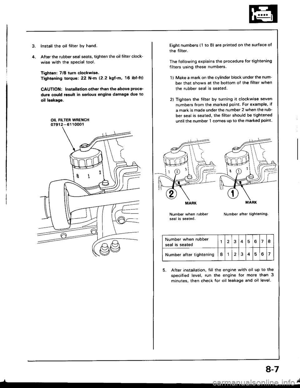
Install the oil tilter by hand.
After the rubber sesl seats, tighten the oil filter clock-
wise with the special tool.
Tighten: 7/8 turn clockwise.
Tightening torque: 22 N.m (2.2 kgf'm, 16 lbf'ft)
CAUTION: Installation other than the abova ploce-
dure could r6suh in serious engine damag€ due to
oil leakage.
OIL FILTEB WRENCH07912-6110001
4.
_l-
8-7
Eight numbers {'l to 8) are printed on the surface of
rhe filter.
The following explains the procedure for tightening
filters using these numbers.
1 ) Make a mark on the cvlinder block under the num-
ber that shows al the bottom of the filter when
the rubber seal is seated.
2) Tighten the tilter by turning it clockwise seven
numbers from the marked point. For example, if
a mark is made under the number 2 when the tub-
ber seal is seated. the filter should be tightened
until the number 'l comes up to the marked point.
Number when rubberseal is seated.Number after tightening.
MARK
Number when rubber
seal is seated46I
Number after tightening8?o7
5. After installation, till the engine with oil up to the
specified level, run the engine for more than 3
minutes, then check for oil leakage and oil level.
.41
Page 291 of 1413
Fuel Supply System
Fuel Injectors
- --l- - \-l-l
116l- -ltc l-/---r- / ---i- \
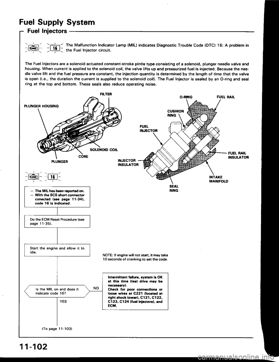
The Fuel Injectors a.e a solenoid-actuated constant-stroke pintle type consisting of a solenoid, plungel n€edle valvs and
housing. When cur.ent is applied to the solsnoid coil, the vslve litts up and pressurized fuel is injected. Because the nee-
dle valve litt and the luel pressure are constant, the iniection quantity is determined by the length of time that the valv€
is open (i.e., the duration the cu.rent is supplied to the solenoid coill. The Fu€l Iniector is sealed by an O-ring and seal
ring at the top and bottom. These seals also reduce operating nois6.
O.RII{G FUEL RAIL
The Malfunction Indicator Lamp (MlL) indicates Diagnostic Trouble Code (DTC) l6: A problem in
the Fuel lniector circuit.
FILTER
PTUNGER
-_-- - ___L-
IrGl- lto l--|.---:_-
- Tho MIL has boen roportod on.- Wilh tho SCS .hon connocto.conoctod (soo pago 11-34),code 16 is indicalod.
Do the ECM Besel Procedure (seepage l l -351.
Intermittant tailura, aystam ir OKat thir tim. (t..1 drivo m.y b.nocaar!ry1.Ch.ck lor poor connactiona ot100!6 wir6!.t C221 (loortod rtright .hock low.rl, C121,C122,Cl23, Cl24 llu6l InFctorrl, lndECM.
ls the MIL on and does itindicate code l6?
NOTE: lf engine willnot start, it may tak6lO seconds ol cranking to sgt th6 code.
{To page 1 1-1O31
11-102