Damper ACURA INTEGRA 1994 Service User Guide
[x] Cancel search | Manufacturer: ACURA, Model Year: 1994, Model line: INTEGRA, Model: ACURA INTEGRA 1994Pages: 1413, PDF Size: 37.94 MB
Page 492 of 1413
Transmission
Removal {cont'd)
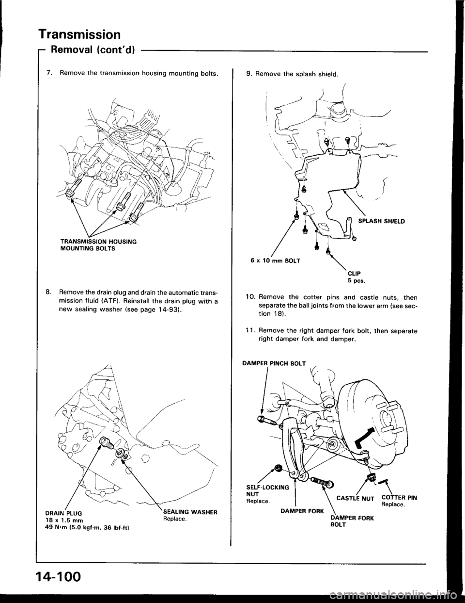
7. Remove the transmission housing mounting bolts.
Remove the drain plug and drain the automatic trans-
mission tluid (ATF). Reinstall the drain plug with anew sealing washer lsee page 14-93).
DRAIN PLUG18 x 1.5 mm49 N'm 15.0 kgt-m,36 tbt-fr)
9. Remove the splash shield.
6 x 10
CLIPS pcs.
10. Remove the cotter pins and castle nuts, then
separate the balljoints from the lower arm {see sec-
tion 18).
11. Remove the right dampe. fork bolt. then separate
right damper fork and damper.
PINCI{ BOLT
SELF.LOCKINGNUTReplace.COTTER PINReplace.
/\
14-100
DAMPER FORK
CASTLE NUT
Page 556 of 1413

Transmission
Installation {cont'd)
14.
15.
Install new set rings on the end of the intermediate
shaft and the driveshaft.
Install the intermediate shaft.
SET RINGBeplace.
16.
10 x 139 N.m14.O kgf.m, 29 lbf.ftl
Install exhaust pipe A. and connect the heated oxv-gen sensor {HO2S) connector.
SELF-LOCKING NUT10 x 1.25 mm54 N.m (5.5 kgl.m,40 rbt.trlReplace.
GASKETReplace.
SELF.LOCKING NUTSI x 1.25 mm22 N.m 12.2 kgl'n,16 lbt.trlRepl6ce.
SHAFT
14-166
DAMPER PINCH BOLT10 x 1.25 mm43 N.m 14.4 kgf.m,32 tbr.ftl
1 7. Install the right and left drivershafts (see section l6l.
NOTE: Turn the right and left steering knuckle fullyoutward, and slide the right driveshaft into the
differential until you feel its spring clip engages theside geaf. Slide the left driveshaft into the intermedi-
ate shaft until you teel the spring clip of the inter-mediate shaft engage the driveshaft.
18. Install right damper fork, then install the right andlett balljoints to each lower arm with the castle nuts
and new cotter Dins.
\
COTTERReplace.CASTLE NUT12 x 1.25 mm49-59 N.m{5.O-6.0 ksf.m, 36-43
SELF.LOCKING NUT12 x 1 .25 mm64 N.m (6.5 kgl.h, 47 lbt.ftlReplace.
rbt'ft1
19. Install the splash shield.
6 x 10 mm BOLT
cltPs, 5
Page 598 of 1413
Driveshafts
Disassembly (cont'd)
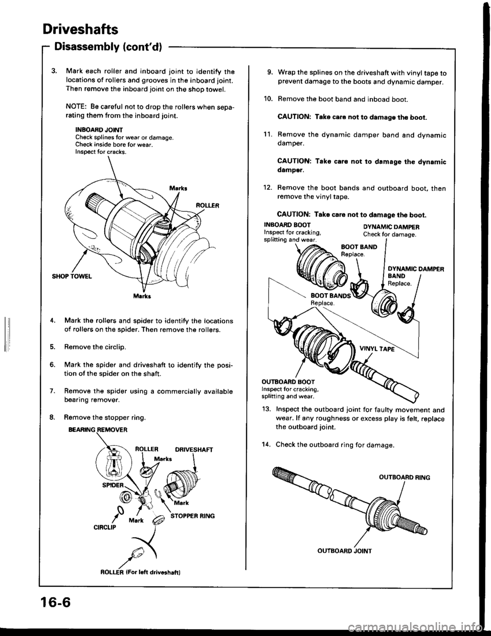
3, Mark each roller and inboard joint to identify the
locations of rollers and grooves in the inboard joint.
Then remove the inboard joint on the shop towel.
NOTE: Be careful not to drop the rollers when sepa-rating them from the inboard joint.
INBOARD JOINTCheck splines tor w6ar or damage.Ch€ck inside bore for wear.Inspect tor cracks.
Mark the rollers and spider to identify the locations
of rollers on the spider. Then remove the rollers.
Remove the circlip.
Mark the spider and driveshaft to identify the posi-
tion of the spider on the shaft.
Remove the spider using a commercially available
bearing remover.
Remove the stopper ring.
BEARING
STOPPER RING
Marka
o.
,'0CIRCLIP
16-6
ROLI-€R lFor loft ddvcshrfrl
9. Wrap the splines on the driveshaft with vinyltape toprevent damage to the boots and dynamic damper.
10. Remove the boot band and inboad boot.
CAUTION: Take car. not to damage th€ boot.
11. Remove the dynamic damper band and dynamicdamoer.
CAUTION: Tako cars not to damage the dynamicdamper.
12. Remove the boot bands and outboard boot, thenremove the vinyltape.
CAUTION: Take csre nol to damage tho boot.
INBOARD BOOTInspect lor cracking,splitting and wear.
DYNAMIC DAMPERCheck tor damage.
DYNAMIC DAMPER
13. Inspect the outboard joint for faulty movement andwear. lf any roughness or excess play is felt, replace
the outboard joint.
14. Check the outboard ring for damage.
OUTBOARD BOOTlnspect for cracking,splining and wear.
OUTBOARD JOINT
Page 599 of 1413
Reassembly
NOTE:
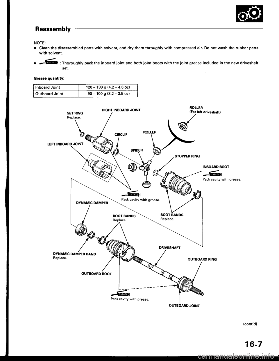
o Clean the disassembled pans with solvent, and dry them throughly with compressed air. Do not wash the rubber parts
with solvent.
ROLI.TR{For lcft
w
o *.'.l|@l : Thoroughly pack the inboard joint and both joint boots with the joint grease included in the new driveshaft
ser.
G.ea3o quontity:
lnboard Joint120 - 130 g |'4.2 - 4.6 ozl
Outboard Joint90 - 100 g {3.2 - 3.5 oz}
INAOARD BOOT
---"-G1Pack cavity with gr€ase.
DYNAMIC DAMPERwrth grease.
SET RINGReplace.
b
,RD JOINT
-GlPack cavity
EOOT BANDSReplace.
(cont'd)
RIGHT INBOARD JOINT
16-7
Page 600 of 1413
Driveshafts
Reassembly (cont'dl
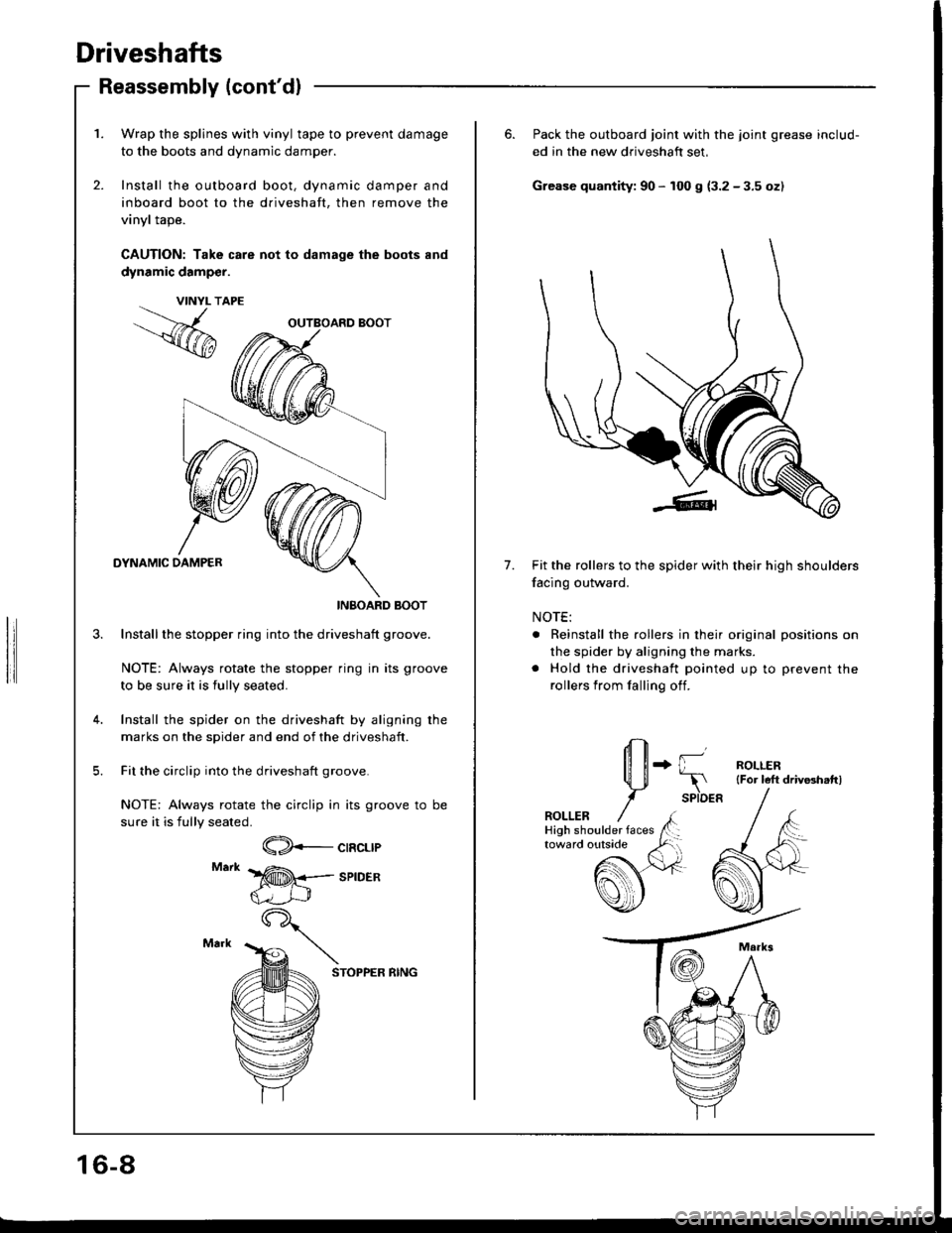
1. Wrap the splines with vinyl tape to prevent damage
to the boots and dynamic damper.
2. Install the outboard boot, dynamic damper and
inboard boot to the driveshaft, then remove the
vinyl tape.
CAUTION: Take care not to damage the boots and
dynamic damp€r.
DYNAMIC DAMPER
INBOARD BOOT
Installthe stopper ring into the driveshaft groove.
NOTE: Always rotate the stopper ring in its groove
to be sure it is fully seated.
Install the spider on the driveshaft by aligning rhe
marks on the spider and end of the driveshaft.
Fit the circlip into the driveshaft groove.
NOTE: Always rotate the circlip in its groove to be
sure it is fully seated.
VINYL T
,.%
CIRCLIP
SPIDER
STOPPER RING
OUTBOARD BOOT
16-8
6. Pack the outboard joint with the joint grease includ-
ed in the new driveshaft set,
Grease quantity: 90 - 100 g (3.2 - 3.5 oz)
7.Fit the rollers to the spider with their high shoulders
facing outward.
NOTE:
. Reinstall the rollers in their original positions on
the spider by aligning the marks.
. Hold the driveshaft pointed up to prevent the
rollers from falling off.
+ {l--r
SPIDER
ROLLER{For left driv8hattl
ROLLER
Page 602 of 1413
Driveshafts
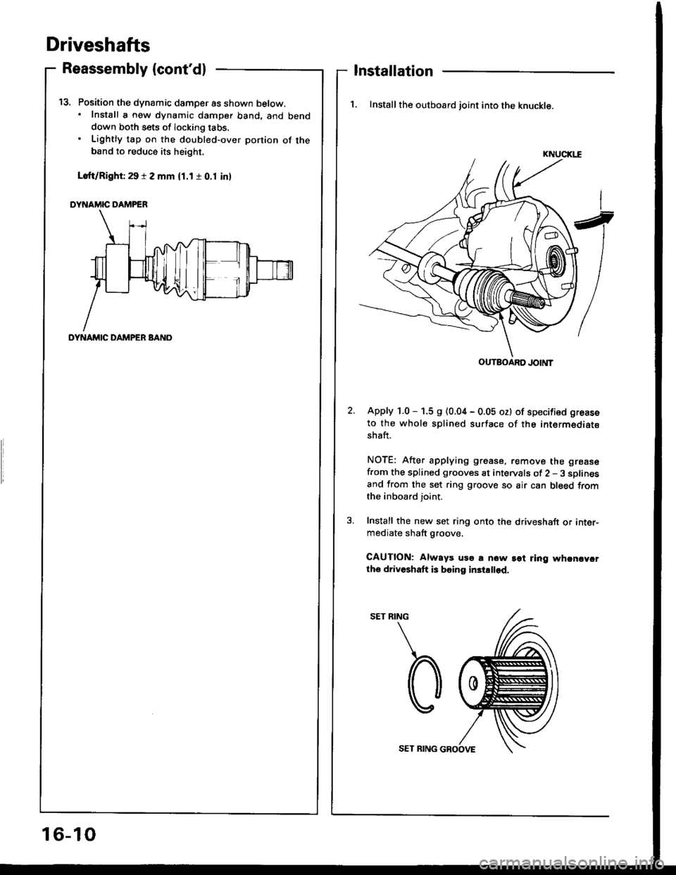
Position the dynamic damper as shown below.. Install a new dynamic damper band. and benddown both sets of locking tabs.
Lightly tap on the doubl€d-over ponion of theband to reduce its height,
Loft/Right 29 r 2 mm (1.1 r 0.1 inl
DYNAMIC DAMPER
t5.
Reassembly (cont'dl
DYNAMIC DAMPER BANO
Installation
1. Install the outboard joint into the knuckle.
KNUCIGE
Apply 1.0 - 1.5 s (0.04 - 0.05 oz) of specified groase
to the whole splined surtace of the intermediatsshaft.
NOTE: After applying grease, remove the grsase
f.om the splined grooves at intervals of 2 - 3 sDlinesand from the set ring groove so air can bleed fromthe inboard joint.
Install the new set ring onto the driveshaft or inter-mediate shaft groove.
CAUTION: Always uso a now sot ring whcncycrtho driveshaft is boing in3tallod.
RING
b
OUTBOARD JOINT
16-10
SET RING GROOVE
Page 603 of 1413
5.
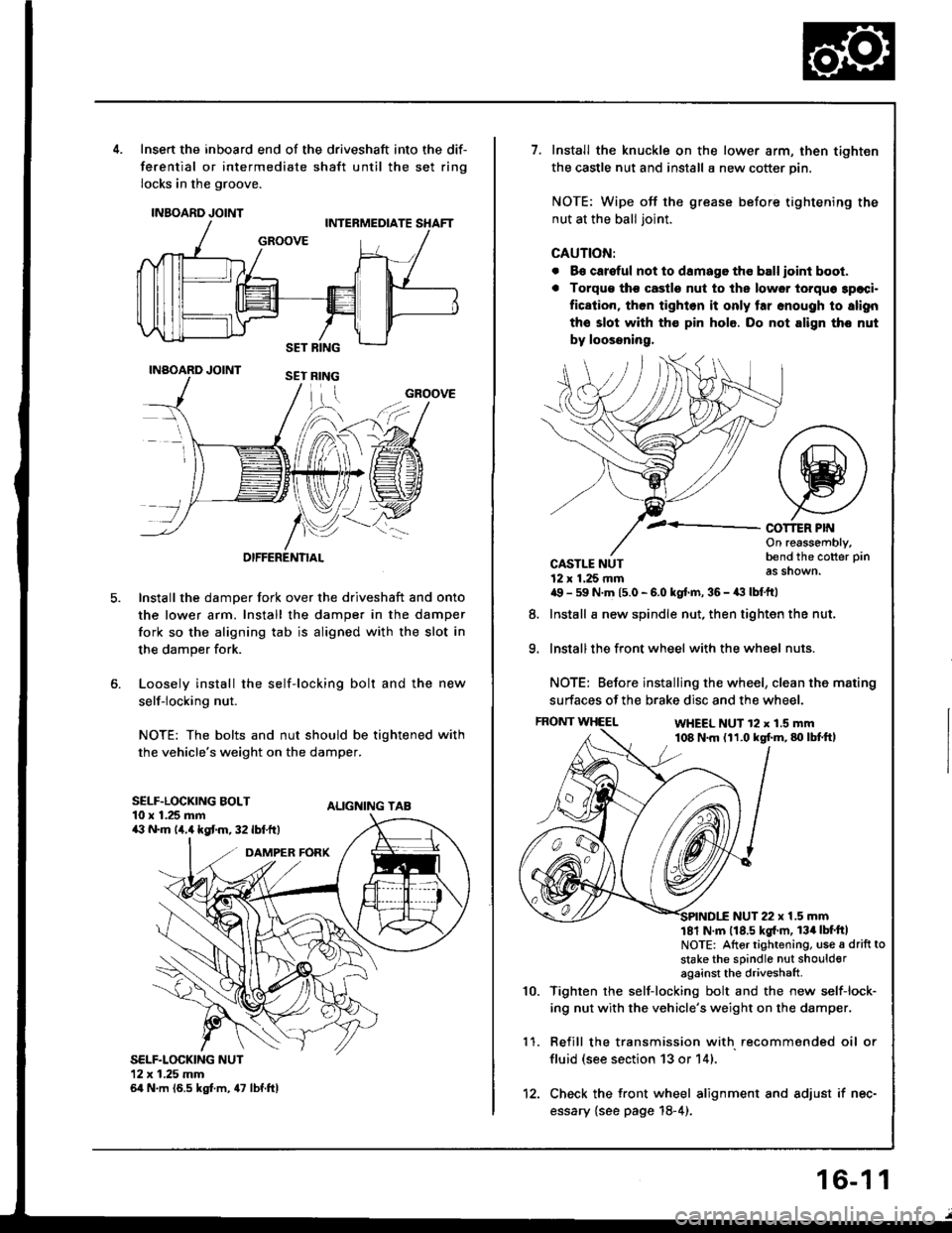
Insert the inboard end of the driveshaft into the dif-
ferential or intermediate shaft until the set ring
locks in the groove.
INBOARD JOINT
INAOARD JOINT
OIFFERENTIAL
Install the damper fork over the driveshaft and onto
the lower arm. Install the damper in the damper
fork so the aligning tab is aligned with the slot in
the damper fork.
Loosely install the self-locking bolt and the new
self-locking nut.
NOTE: The bolts and nut should be tightened with
the vehicle's weight on the damper.
ALIGNING TAB
SELF.LOCKING NUT12x 1.25 mm64 N.m (6.5 kgt m, 47 lbf.ftl
GROOVE
SELF.LOCKING BOLT10 x 1.25 mma:' N.m lir,4 kgt m, 32 lbf.ftt
1.Install the knuckle on the lower arm, then tighten
the castle nut and install a new cotter pin.
NOTE: Wipe off the grease before tightening the
nut at the ball joint.
CAUTION:
. B€ careful not to damago tho ball ioint boot.
. Torqu€ tho castle nut to ths lower torquo 3paci.
fication, then tighlon it only tar snough to slign
the slot with th€ pin hole. Do not align tho nut
by loossning,
COT1ER PIf{On reassembly,bend the cotter pin
as shown.
9.
CASTLE NUT12 x 1.25 rnma9 - 59 N.m 15.0 - 6.0 kgt.m, 36 - a:t lbtftl
Install a new spindle nut, then tighten the nut,
Install the front wheel with the wheel nuts.
NOTE: Before installing the wheel, clean the mating
surfaces of the brake disc and the wheel.
FRONT WHEELWHEEL NUT 12 x 1.5 mm108 N.m (11.0 kgf.m,80lbtft,
8.
1 '�I.
10.
NUT 22 x 1.5 mm181 N m 118.5 kgl'm, 134lbt'ftlNOTE: Altor tightening, use a drift to
stake the sPindle nut shoulderagainst the driveshaft
Tighten rhe self-locking bolt and the new self-lock-
ing nut with the vehicle's weight on the damper.
Refill the transmission with recommended oil or
fluid (see section 13 or 14).
Check the front wheel alignment and adjust if nec-
essary {see page 18-4).
12.
16-1 1
Page 1004 of 1413
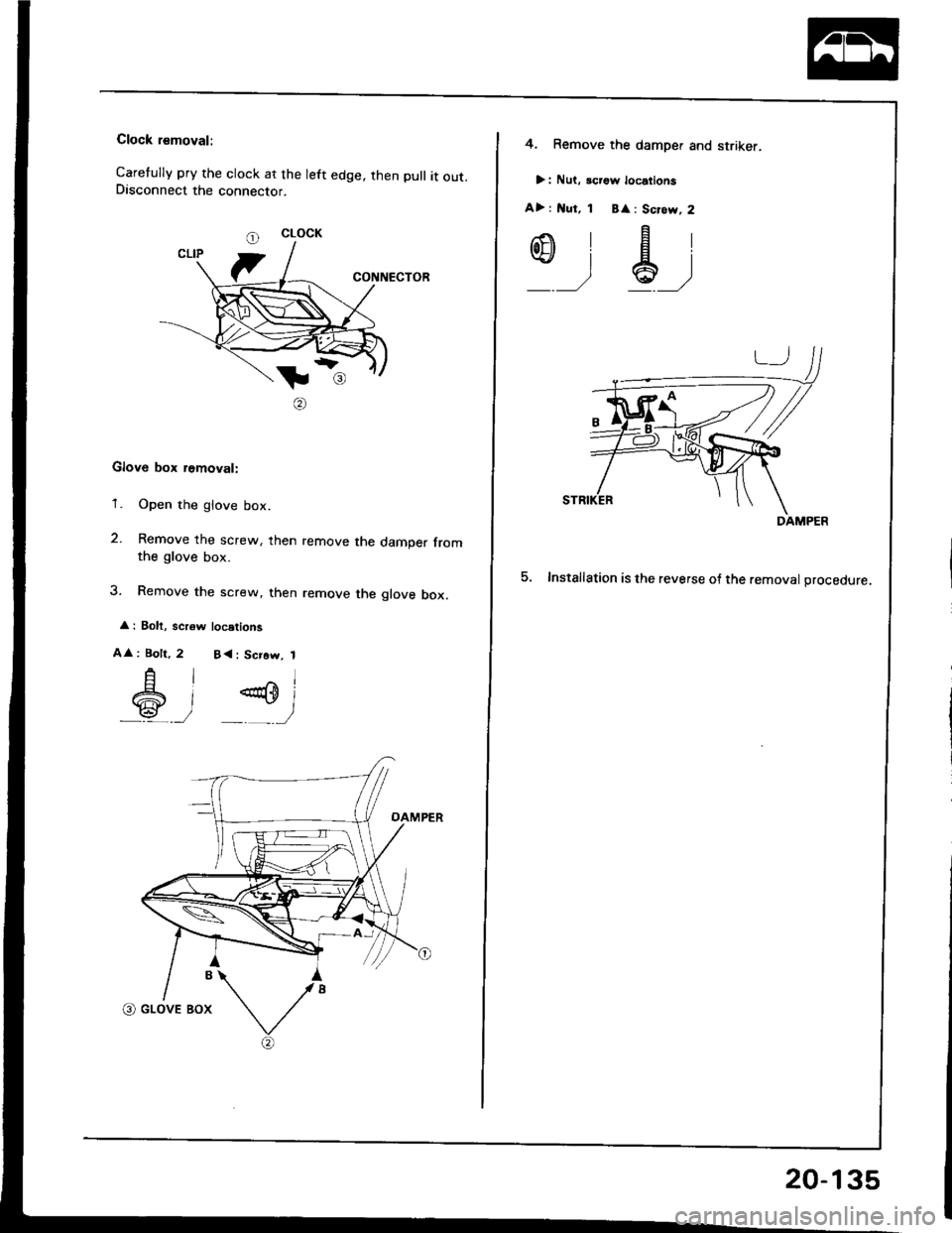
Clock rsmoval:
Caretully pry the clock at the left edge. then pull it out.Disconnect the connector.
CONNECTOR
tl
@
Glove box removal:
'1. Open the glove box.
2. Remove the screw, then remove the damper fromthe glove box.
3. Remove the screw, then remove the glove box.
: Bolt, scr6w locstions
A
: Bolt,
A
6
l^l
)P)
2 B<: Scrow, 1
CLOCK
4. Remove the damper and striker.
>: Nut, icrgw locations
A> : l{ut, 1 B
: Scrow, 2
,-.\'Flot]}lEl\+!lal
_ __,/ *' ,/
5. Installation is the reverse o{ the removal orocedure.
DAMPER
20-135
Page 1061 of 1413
Heater Unit
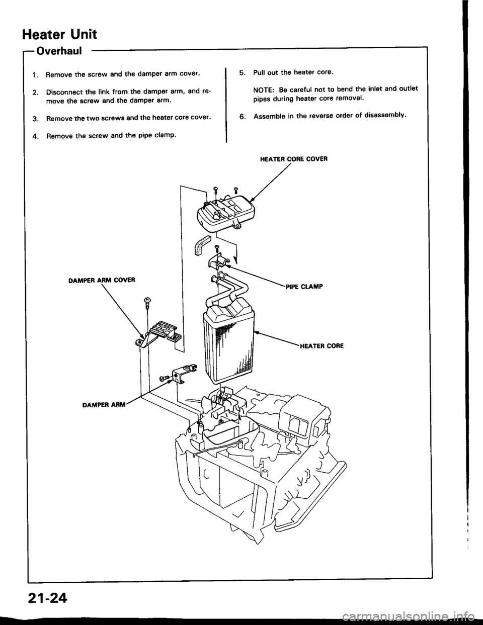
Overhaul
Remove the screw and the damper arm cover.
Disconnect the link from the dampar arm, and re-
move the screw and the damper arm.
Removs the two screws and the heater core cover.
Remove the screw and the pipe clamp.
Pull out the heater core.
NOTE: Be careful not to bend the inlet and outlet
pipes during heater core removal.
Assemble in the rev€rse older of disassembly.
1.
?
4.
HEATER CORE COVER
DAMPER ARM COVER
HEATER CORE
DAMPEF ARM
21-24
Page 1378 of 1413
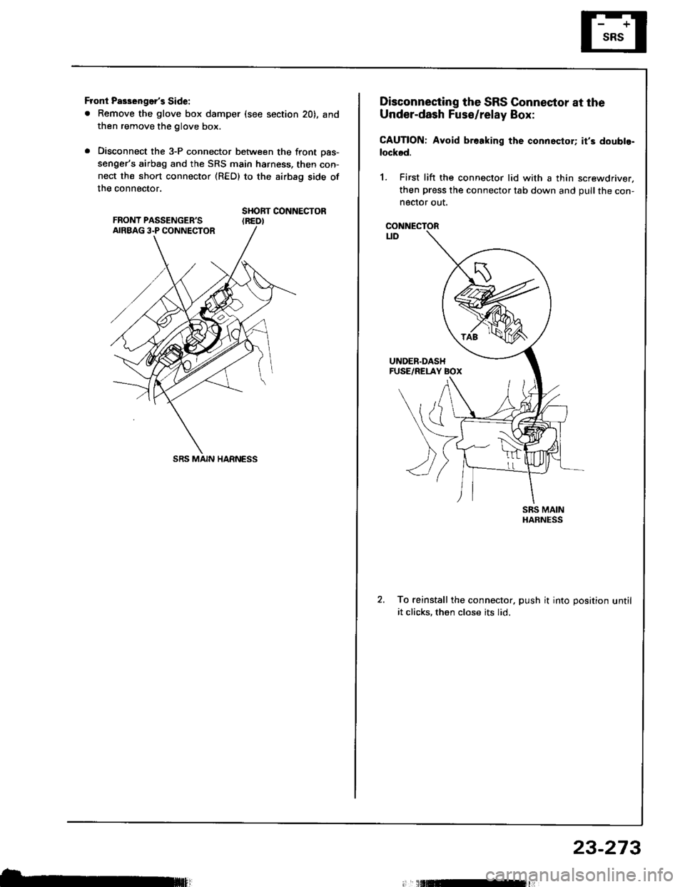
Front Pas3enger's Side:
. Remove the glove box damper (see section 20), and
then remove the glove box.
. Disconnect the 3-P connector between the front oas-
senger's airbag and the SRS main harness, then con-
nect the short connector (RED) to the airbag side of
the connector.
SHORT CONNECTOR(REDI
SRS MAIN HARNESS
b,
Disconnecting the SRS Connector at the
Under-dash Fuse/relay Box:
CAUTION: Avoid br.aking the connoctor; it's doubte-
locksd.
1. First lift the connector lid with a thin screwdriver,
then press the connector tab down and pull the con-neclor out.
CONNECTORt_tD
To reinstall the connector. push it into position untilit clicks, then close its lid.
23-273