low oil pressure ACURA INTEGRA 1994 Service Owner's Manual
[x] Cancel search | Manufacturer: ACURA, Model Year: 1994, Model line: INTEGRA, Model: ACURA INTEGRA 1994Pages: 1413, PDF Size: 37.94 MB
Page 479 of 1413
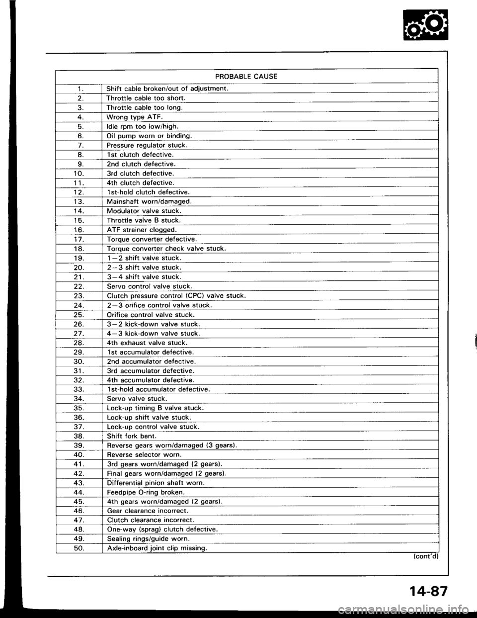
PROBABLE CAUSE
1Shitt cable broken/out of adiustment.
Throttle cable too short.
Throttle cable too long.
Wrong type ATF.
ldle rpm too low/high.
o.Oil pump worn or binding.
7.Pressure regulator stuck.
8.l st clutch detective.
9.2nd clutch detective.
10.3rd clutch defective.
114th clutch defective.
12.1 st'hold clutch defective.
13.Mainshatt worn/damaged.
14.Modulator valve stuck.
Throttle valve B stuck.
lo.ATF strainer clogged.
Toroue converter def ective.
18.Torque converter check valve stuck.'I 9.1-2 shift valve stuck.
2-3 shift valve stuck.
213-4 shift valve stuck.
Servo control valve stuck.
23.Clutch Dressure control (CPC) valve stuck.
2-3 orifice control valve stuck.
Orifice control valve stuck.
26.3-2 kick-down valve stuck.
27.4-3 kick-down valve stuck.
24.4th exhaust valve stuck.
29.1st accumulator detective.
30.2nd accumulator detective.
313rd accumulator defective.
4th accumulator defective.
1 st-hold accumulator defective.
Servo valve stuck.
35.Lock-up timing B valve stuck.
36.Lock-up shift valve stuck.
37.Lock-uo control valve stuck.
38.Shift fork benr.
39.Reverse gears worn/damaged (3 gears).
40.Reverse selectot worn.
413rd gears worn/damaged (2 gears).
Final qears worn/damaged (2 gearsl.
43.Differential Dinion shatt worn.
44.Feedpipe O-ring broken.
45.4th qears worn/damaged (2 gearsl
Gear clearance incorrect.
47.Clutch clearance incorrect.
48.One-way (sprag) clutch defective.
49.Sealinq rings/quide worn.
50.Axle-inboard joint clip missing.
Page 481 of 1413
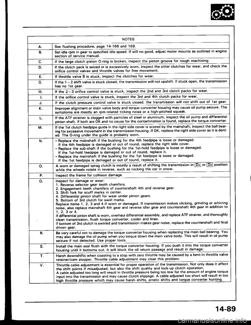
NOTES
A.See flushing procedure, page l4-168 and 169.
B.Set idle rpm in gear to specitied idle speed. lf still no good, adiust motor mounts as outlined in engine
section of service manual.
lf the large clutch piston O-ring is broken, inspect the piston groove for rough machining.
lf the clutch pack is seized or is excessively worn, inspect the other clutches Jor wear, and check the
orifice control valves and throttle valves for free movement.
E.It throttle valve B is stuck, inspect the clutches for wear.
lf the 1-2 shift valve is stuck closed, the transmission will not upshift. lI stuck open, the transmission
has no lst gear.
H.lf the 2-3 orifice control valve is stuck, inspect the 2nd and 3rd clutch packs for wear.
ll the orifice cont.ol valve is stuck, inspect the 3rd and 4th clutch packs for wear.
lf the clutch Dressure control valve is stuck closed, the transmission will not shilt out of 1st gear.
K.improper alignment or main valve body and torque converter housing may cause oil pump seizure. The
symptoms ale mostly an rpm-related ticking noise or a high-pitched squeak.
L.ll the ATF strainer is ctogged with panicles of steel or aluminum, inspect the oil pump and ditferential
pinion shaft. lt both are OK and no cause lor the contamination is found, replace the torque converter.
M.lf the 1st clutch feedpipe guide in the right side cover is scored by the mainshaft, inspect the ball bear-
ing for excessive movement in the transmission housing. lf OK. replace the right side cover as it is dent-
ed. The O-ring under the guide is probably worn.
N.ReDlace the mainshstt if the bushing for the 4th feedpipe is loose or damaged.
It the 4th feedpipe is damaged or out ot tound, replace the right side cover'
Replace the subjshaft it thtbushing for the 1st-hold Jeedpipe is loose or damaged.
lf the 1st-hold feedpipe is damaged or out of round, replace it.
Replace the mainshaft if the bushing lor the 1st feedpipe is loose or damaged.
lf the lst feedpipe is damaged or out ot round, replace it.
o.A *o- r, da."s"d "p-g clutch is mostly a result of shifting the transmission in El or Lq! position
while the wheels rotate in reverse, such as rocking the car in snow.
P.InsDect the frame for collision damage.
o.Inspect for damage or wear:
1. Reverse selector gear teeth chamfers.
2. Engagement teeth chamters of countershaft 4th and reverse gear.
3. Shift fork for scutt marks in center.
4. Differential Dinion shaJt for wear under pinion gears.
5. Bottom of 3rd clutch for switl marks.
Replace items 1 , 2, 3 and 4 it worn or damaged. lf transmission makes clicking, grinding or.whirring
noise, atso replace mainshaft 4th gear and reverse idler gear and countershaft 4th gear in addition to
1,2,3ot4.lf ditiersntial Dinion shaft is worn, overhaul differential assembly, and replace ATF strainel, and thoroughly
clean transmission, tlush torque convertet, cooler and lines.
lf bottom of 3rd clutch is swirled and transmission makes gear noise, replace the countershaft and tinal
driven gear.
R.Be wry careful not to dsmage the torque converter housing when replacing the main ballbearing. You
may al;o damage the oil pump when you torque down the main valve body. This will result in oil pump
seizure it not detected. Use proper tools.
qInstall the main seal tlush with the torque converter housing, lf you push it into the torque converter
housing until it bottoms out. it will block the oil return passage and result in damage.
T,Harsh do\/vnshiJt"\./l,'hen coasting to a stop with zero th.ottle may be caused by a bent-in throttle valve
retainer/cam stopper. Throttle cable adjustment may clear this problem.
ifuitle cable adjustment is essential for proper operation of the transmission. Not only does it affect
the shift points if misad,usted, but also the shift quality and lock-up clutch operation'
A cable adjusted too long will result in throttle pressure being too low for the amount of engine torque
input into ihe trsnsmission and may cause clutch slippage. A cable adjusted too short will result in too
hi;h throttle pressure which may cause harsh shitts, erratic shrfts and torque con
14-89
Page 484 of 1413
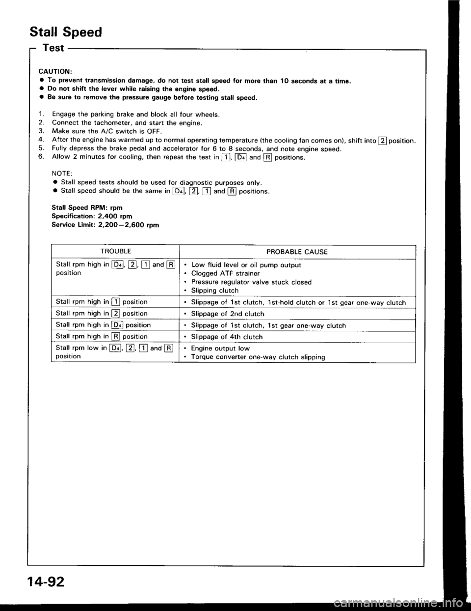
Stall Speed
CAUTION:
a To plevent transmission damage, do not test stall speed fot mote than 1O seconds at a time.a Do not shift the level while raising th€ engine speed.a Be sure to remove the pressure gauge belot€ testing stall speed.
1. Engage the parking brake and block all four wheels.
2. Connect the tachometer, and start the engine.
3. Make sure the A/C switch is OFF.
4. After the engine has warmed up to normal operating temperature (the cooling lan comes on), shift into ft position.
5. Fully depress the brake pedal and accelerator for 6 to 8 seconds. and note engine speed.6. Allow 2 minutes for cooling, then repeat the test in [, fDil and @ positions.
NOTE:
a Stall speed tests should be used lor diagnostic purposes only.. Stall speed should be the same in E, tr. tr and @ positions.
Stall Speed RPM: rpm
Specification: 2,400 rymService Limit: 2,2OO-2,600 tpm
TROUBLEPROBABLE CAUSE
Stall rpm hish in E, E, I and @posrtronLow fluid level or oil pump output
Cloqged ATF strainer
Pressure regulator valve stuck closed
Slipping clutch
Stall rpm high in I positionSlippage of 1st clutch, 1st-hold clutch or 1st gear one-way clutch
Stall rpm high in @ positionSlippage of 2nd clutch
Stall rpm high in @ positionSlippage of 1st clutch, lst gear one-way clutch
Stall rpm high in @ positionSlippage of 4th clutch
Stall rpm low in E, E, I ana @positionEngine output low
Torque converter one-way clutch slipping
14-92
Page 486 of 1413
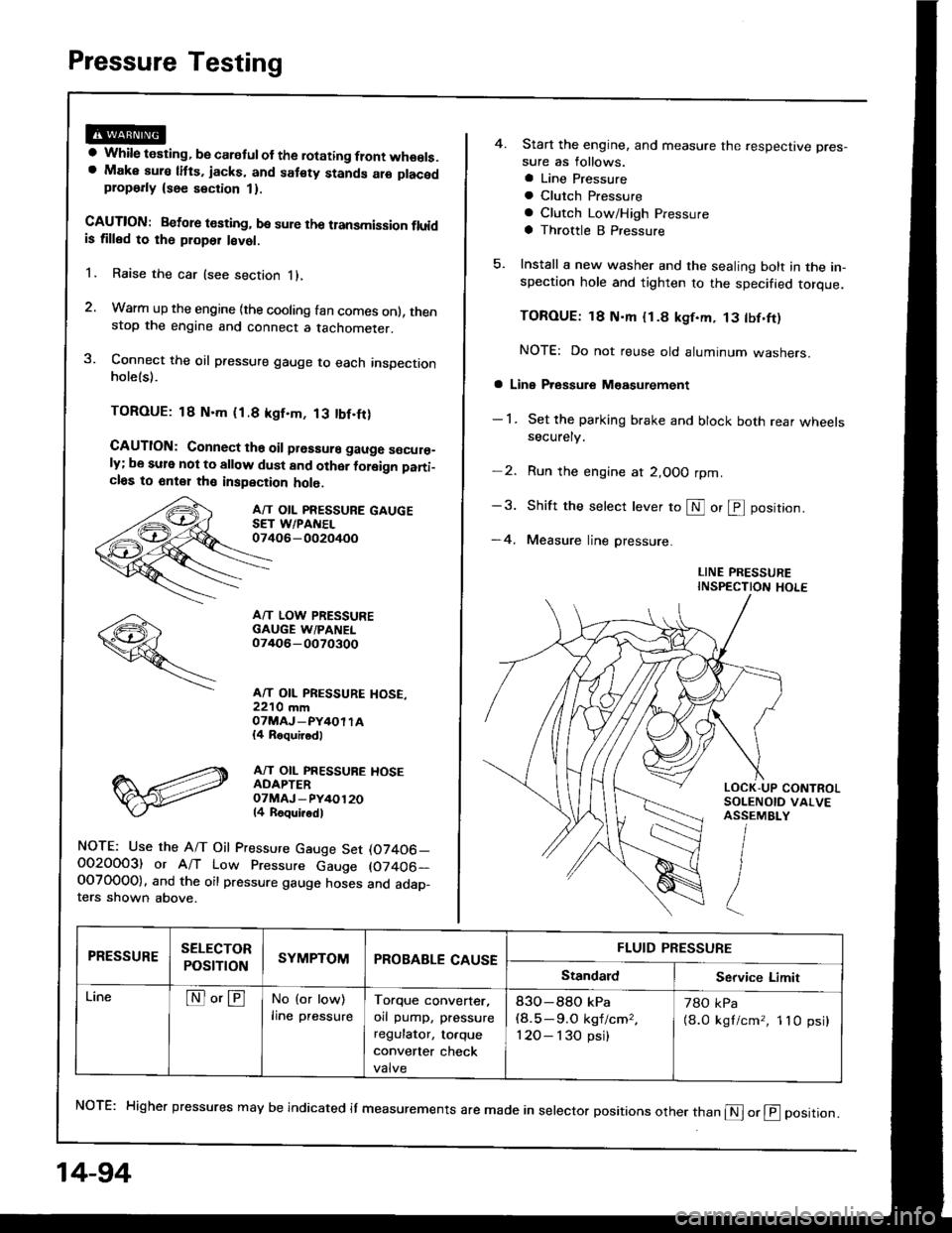
Pressure Testing
a While testing, be caretul of the rotating flont wheels.a Make aura litts, jacks, and sat€ty stands alo placedplop6rly {see section 1}.
CAUTION: Betore t€sting, be sure the transmission fluidis tilled to rh6 ploper l€vet.
1. Raise the car (see section i),
2. Warm up the engine {the cooling fan comes onl, thenstop the engine and connect a tachometer.
3. Connect the oil pressure gauge to each inspectionholels).
TOROUE: 18 N.m (1.8 kgf.m, 13 tbf.fr)
CAUTION: Connect ths oil prsssure gauge s€cur€_ly; be sule not to allow dust and other foleign pani_cl6s to 6nt€1 th€ inspection holo.
A/T OIL PRESSURE GAUGESET WPANEL07406-002oi+oo
A/T LOW PRESSUREGAUGE W/PANEL07/rO6-0O70300
A/T OIL PRESSURE HOSE,22'10 mmOTMAJ_PY4OI TA{4 Roquirod)
A/T OIL PRESSUBE HOSEADAPTEROTMAJ - PY/+O12014 Roqui.odl
NOTE: Use the A/T Oil Pressure Gauge Set (07406_O02OOO3) or A/T Low Pressure Gauge (07406-OOTO0OO). and the oil pressure gauge hoses and adap_ters shown above.
14-94
4. Start the engine, and measure the respective pres-
sure as follows.
a Line Pressure
a Clutch Pfessure
a Clutch Low/High Pressure
a Throttle B Pressure
5. Install a new washer and the sealing bolt in the in-spection hole and tighten to the specified torque.
TOROUE: 18 N'm {1.8 kgf.m, 13 tbf.ft)
NOTE: Do not reuse old aluminum washers.
a Line Pressure M€asurement
- 1 . Set the parking brake and block both rear wheelssecurely.
-2. Run the engine at 2,OOO rpm
-3. Shift the selecr lever to S or @ position.
-4. Measure line pressure.
LINE PRESSUREINSPECTION HOLE
NoTE: Higher pressures may be indicated it measurements are made in selector positions other than @ or @ position.
PRESSURESELECTOR
POStTTONSYMPTOMPROBABLE CAUSEFLUID PRESSURE
StandardService Limit
LineNo'ENo (or low)
lrne pressureTorque converter,
orl pump, pressure
regulator, to.que
convener check
valve
83O-88O kPa(8.5-9.O kgf/cm,,
120- I 30 psi)
78O kPa
{8.0 kgl/cm,, 1lO psi}
Page 488 of 1413
Pressure Testing
(cont'dl
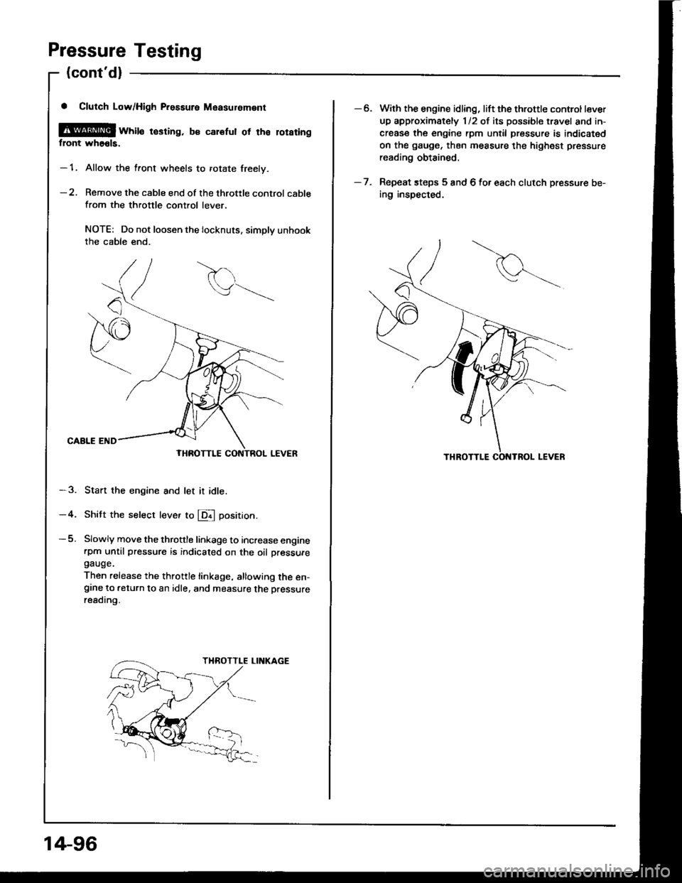
a Clutch Low/High P.essure Measuroment
@[ wtite resring. b€ calefut ot tha loraringflont wh66ls.
- 1. Allow the front wheels to rotate freely.
-2. Remove the cable end of the throttle control cable
from the throttle control lever.
NOTE: Do not loosen the locknuts. simplv unhookthe cable end.
CAALE END
-3. Start the engine and let it idle.
-4. Shitt the select leve. to E position.
-5. Slowly move the throttle linkage to increase enginerpm until pressure is indicaied on the oil oressuregauge.
Then release the throttle linkage, allowing the en-grne to return to an idle, and measure the Dressureresding.
14-96
-6. With the engine idling, lift the throttle control lever
up approximately 1/2 of its possible travel and in-
crease the engine rpm until pressure is indicated
on the gauge, then measure the highest pressure
reading obtained.
- 7. Repeat steps 5 and 6 for each clutch pressure be-
ing inspected.
Page 490 of 1413
Pressure Testing
(cont'dl
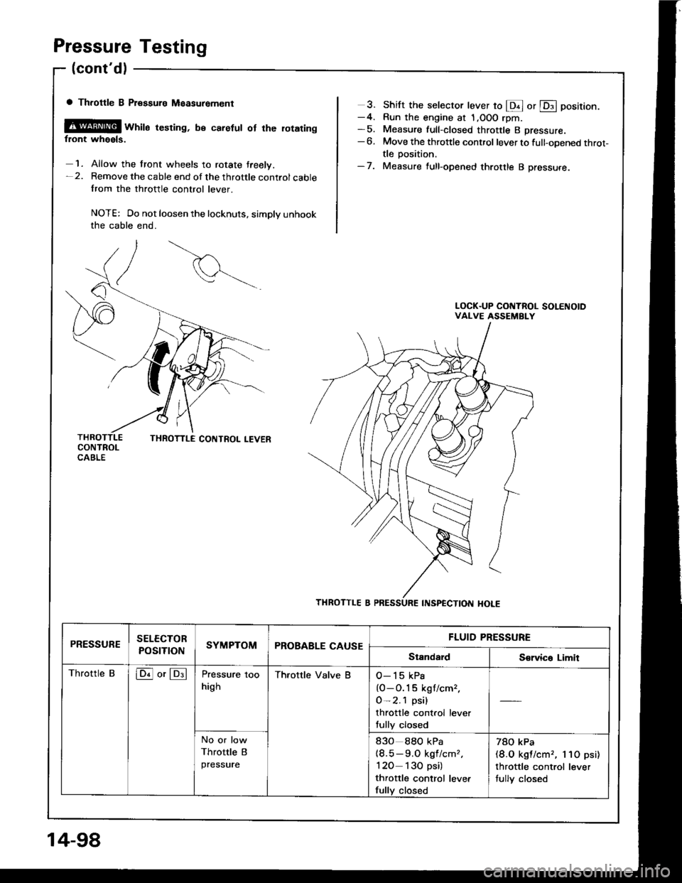
a Throttle B Ptsssure Measuremcnt
@@ wrril" resring, be caretut ot rhe rotaringfront wheels.
1. Allow the front wheels to rotate treelv.-2. Remove the cable end of the throttle controlcablefrom the throttle control lever.
NOTE: Do not loosen the locknuts, simply unhookthe cable end.
3. Shift the selector lever to @ or @ position.-4. Run the engine at 1,OOO rpm-5. Measure full-closed throttle B pressure.-6. Move the throttle control lever to full-opened throt-tle position.-7. Measure full-opened throttle B pressure.
PRESSURESELECTOR
POSTTTONSYMPTOMPROBABLE CAUSEFLUID PRESSURE
StandardS€rvica Limit
Throttle Bloil or lDllPressure too
high
Thfottle Valve BO-15 kPa
{O-O.1 5 kgf/cm,,
0-2.1 psi)
throttle control lever
fully closed
No or low
Throttle B
pressure
83o 88O kPa(8.5-9.O kgf/cmz,
120 130 psi)
thfottle control levet
fully closed
78O kPa(8.O kgl/cm,, l lO psi)
throttle control lever
tully closed
14-98
Page 558 of 1413
Transmission
Cooler Flushing
S!@ ro prevent iniury to tace and eyes, always
wear safety glas$es or a tace shield when using the trans-
mission flusher.
NOTE: This procedure should be performed before rein-
stalling the transmission.
1. Check tool and hoses for wear or cracks before
using.
lf wear or cracks are found, replace the hoses be-
fore using.
2. Using the measuring cup, tillthe tank with 21 ounces
{approximately 213 lulll of biodegradable tlushing
fluid (J35944-20). Do not substitute with any other
fluid.
Follow rhe handling procedure on the fluid container.
Secure the tlusher filler cap and pressurize the tank
with compressed air to between 550-829 kPa(5.6-8.45 kgt/cm,, 80- 120 psi),
NOTE: The air line should be equipped with a water
trap to ensure a dry air system.
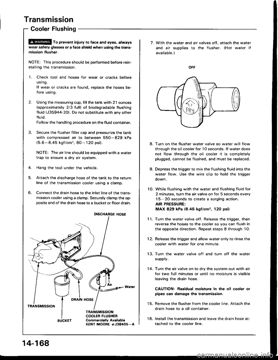
Hang the tool under the vehicle.
Attach the discharge hose of the tank to the return
line of the transmission cooler using a clamp.
Connect the drain hose to the inlet line of the trans-
mission cooler using a clamp. Securely clamp the op-posite end of the drain hose to a bucket or floor drain.
6.
DRAIN HOSE
TRANSMISSION
TRANSMISSIONCOOLER FLUSHEBCommorcially AvailabloKENT MOORE #J38405_A
DISCHARGE HOSE
14-168
BUCKET
7. With the water and air valves off. attach the water
and air supplies to the flusher. (Hot water it
available.)
OFF
8. Turn on the flusher water valve so water will tlow
through the oil cooler for 1O seconds. lf water does
not flow through the oil cooler it is completely
plugged, cannot be flushed, and must be replaced.
9. Depress the trigger to mix the tlushing lluid into the
water tlow. Use the wire clip to hold the trigger
oown.
10. While flushing with the water and flushing fluid for
2 minutes. turn the air valve on for 5 seconds every
15-20 seconds to create a surging action.
AIR PRESSURE:
MAX 829 kPa (8.45 kgt/cm,, 12O psi)
1 1. Turn the water valve off. Release the trigger, then
reverse the hoses to the cooler so you can flush in
the opposite direction. Repeat steps 8 through 1O.
12. Release the trigger and allow water only to rinse the
cooler with water for one minute.
13. Turn the water valve off and turn off the water
supply.
14. Turn the air valve on to dry the system out with air
for two full minutes or until no moisture is visible
leaving the drain hose.
CAUTION: Residual moisture in the oil cooler 01
pipes can damage the transmission.
15. Remove the flusher trom the cooler line. Attach the
drain hose 10 a oil container.
16. lnstallthe transmission and leave the drain hose at-
tached to the cooler line.
Page 1074 of 1413
Description
Outline
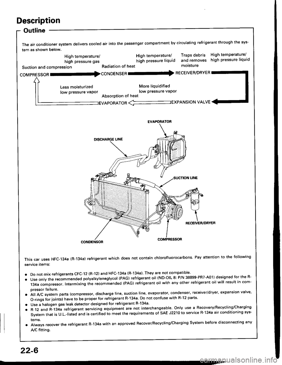
The air conditioner system delivers cooled air into the passenger compartment by circulating refrigerant through the sys-
tem as shown below.
CONDENSOR
This car uses HFC-134a {R-134a) refrigerant which does not contain chlorofluorocarbons Pay attention to the following
service items:
. Do not mix refrigerants CFC-I2 (R-l21 and HFC-134a (R-134a) They are not compatible'
. Use onty the recommended potyatkytenegtycol {PAG) refrigerant oil (ND-OIL 8: P/N 38899-PR7-A01) designed for the R-
134a compressor. Intermixing the recommended (PAG) refrigerant oil with any other refrigerant oil will result in com-
pressor tailure.
.A||lvcsystemparts(compressor.dischargeIine,suotionIine,evaporator,condenser.receiver/dryer,expansionva|ve.
o-ringsforioints}havetobeproperforre'rigerantR-l34a.DonotconfusewithR.l2parts.
. Use a halogen gas leak detector designed for refrigerant R-134a'
. R-.12 and C-l34a refrigerant servicing equipment are not interchangeable. Only use a Recovery/Recyclins/Charging
System that is U.L.-listed and is certifLd to meet the requirements of sAE J2210 to service R-134a air conditioning sys-
rems.
. Always recover the refrigerant R-134a with an approved Recover/Recycling/Charging System before disconnecting any
A,/C fitting.
coMpRESsoR -coNDENSER - RECEIVER/DRYER
High temperature/
high pressure gas
Suction and comPression
Less moisturized
low pressure vaPor
High temperature/ Traps debris High temperature/
hilh pressure liquid and removes high pressure liquid
Radiation of heat molsture
More liquidified
low Pressure vaPor
Absorption of heat
EVAPORATOR <-'----------.- EXPANSION VALVE
EVAFORATOR
22-6
Page 1089 of 1413
A/C Service Tips and Precautions
The air conditioner system uses HFC-134a (R-134a) .efrigerant and polyalkyleneglycol (PAG) retrigerant oil (ND-OIL g: p/N
38899 - PR7 - A0l ), which are not compatible with CFC-12 \R-'12) refrigerant and mineral oil. Do not use R-12 refrigerant ormineral oil in this system, and do not attempt to use R-'12 servicing equipment; damage to the air conditioner system oryour servicing equipment will result.
only use service equipment that is u.L,-listed and is certified to meet the requirements of sAE J2210 to remove R-134afrom the air conditioner svstem.
CAUTION: Exposure lo air conditioner refrigorant and lubricanl vapor or mi3t cln irritato gyos, nose and throat. Avoidbreathing lhe air conditioner refrigerant and lubricant vapor or mist.
lf accidental system discharge occurs, ventilate work area befor€ resuming service.R-134a service equipment or vehicle air conditioner systems should not be pressure tested or leak tested with compressedair.
@ some mirtures of air and R-l3ifa have been 3hown to be combu3tible at slsvated prossuros and can relultin fire or explosion causing inlury or property damage. Never use complessod ai. to prgssure t€|st R-134a service equip-ment or vehicle air conditiongr systems.
Additional health and safety information may be obtained from the refrigerant and lubricant manufacturers.'1. Always disconnect the negative cable from the battery whenever replacing air conditioning pans.
2. Keep moisture and dust out of the system. When disconnecting any lines, plug or cap the fittings immediately; don'tremove the caps or plugs until just before you reconnect each line.
3. Before con necting a ny hose or line, apply a few drops of refrigerant oil (ND-OIL 8: P/N 38899 - PR7 - AO1) to the O-ring.4. When tightening or loosening a fitting, use a second wrench to support the matching fitting.5. When recovering the system, use a R-134a refrigerant Recovery/Recycling/Charging System; don't release refrigerantinto the atmosDhere.
6. Add refrigerant oil (ND-OlL 8: P/N 38899 - PR7 - A01) after replacing the following parts:
NOTE:
. To avoid contamination, do not return the oil to the container once dispensed, and never mix it with other refriqer-ant orls.
. lmmediately after using the oil, replace the cap on the container and seal ittoavoid moisture absorption,. Do not spill the refrigerant oil on the car; it may damage the paint; if the re{rigerant oil contacts the paint, wash itoff immediately.
Condenser ..................... 25 m/ (5/6 fl.oz, 0.9 lmp.oz)
Evaporator ................. ilo mf 17 113fl.oz,1.4 lmp.oz)
Line or hose 10 ml (1/3 fl.oz. o.il lmp'ozl
Receiver/Dryer .....,.,,...., 10 m{ l1l3 tl.oz, 0.4 lmp.ozl
Leakage repair .............. 25 mf (5/6 fl.oz, 0.9 lmp.ozl
Compressor For compressor .eplaco-
m€nt, subtract the volumo of oil drained from tho
removed compressor trom 140 ml 11 213 ll.oz, 1,9
imp.ozl, and drain the calculalgd volume of oil from
tho new compressor: 140 mf 11 213 ll. oz, 1.9
imp.ozl- Volume ot removod compressor = Volume
to drain from n€w compressor.
NOTE: Even if no oil is drained from the removed
compiessor, don't drain more than 50 ml 11 213
fl.oz, 1.8 lmp .oz) from the new comDressor.
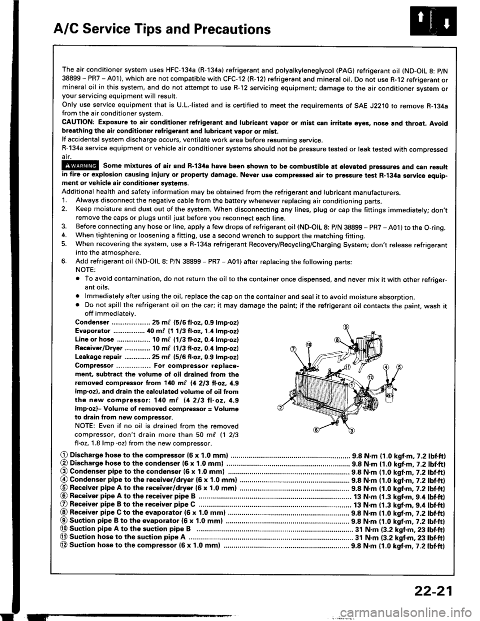
O Dischargo hose to the compresso. (6 x 1.0 mml .............................. 9.8 N.m {1.0 kgt.m, 7.2 lbf.ft)(, Discharge hosa to ths condenser (6 x 1.0 mm) . 9.8 N.m {1.0 kgf.m, j.Z lbl.ftl@ Condenser pipe to tho condenser (6 x 1.0 mml 9.8 N.m n.O kaf.m,t-2tbl.ftl
@ Condenser pipe to the receiver/dryer (6 x 1.0 mm) ......................... 9.8 N.m (1.0 katm,7.2 lbf.ft)@ Receiver pipe A to tho receiver/dryer 16 x 1.0 mm) ......................... 9.8 N.m (1.0 kttm. 7.2 lbt.ft)@ Receiver pipe A to th6 receiver pipe B ......................................
O Receiver pipe B to the receiver pipe C .............................................. 13 N.m {1.3 kgt.m. 9.4 lbt'ft)
13 N.m {1.3 kgf.m.9.4 lbf'ft)@ Receiver pipe C to the evaporator (6 x 1.0 mm) 9.8 N.m {1.0 kgf.m , j.Zlbl.ftl
@Suaion pip€ B to the evaporator {6x 1.0 mm) ................ ................ 9.8 N.m tt.O t!f.-, r.Z tUt tt}@ Sustion pipe A to the suction pipe B .................. 3t N.m (3.2 klnm,23 lbf.ft)(, Suction hose lo the suction pipe A ................ ...... 31 N.m (3.2 kgf.m, 23 tbf.ftl
OA Suction hose to the compressor {5x 1.0 mm} ................ ................. 9.8 N.m 11.0 kgt.m,7.2 lbf.ft)
ET
22-21
Page 1090 of 1413
A/C System Service
Recovery
Onlv use service equipment that is U.L.-listed and is cer-
tified to meet the requirements of SAE J2210 to remove
HFC-134a (R-134a) from the air conditioner system.
CAUTION: Expo3ute to air conditioner rcfrigelant rnd
lubricant vapor or mist can irritatc oyo!, no3o and
throat. Avoid bresthing the lir condhionot rofrigorlnt
and lubricant vapor or misl.
lf accidental system discharge occuts, ventilate work
area before resuming service.
R-134a service equipment or vehicle air conditioner sys-
tems should not be pressure tested or leak tested with
comoressed air.
!!@ some mixturos ot Eir and R'134. hsvc
bsen shown to be combu3tible st elavllcd prs33urc3
and can result in fire or oxplosion cau3ing iniurY or
property damage, Nsvor u36 comprg3Sod lir to P|'�3turl
test R-134a servic€ equipmont o. vohiclc rir condhioncr
3ystems.
Additional health and safety information may be
obtained from the refrigerant and lubricant manufac-
rures.
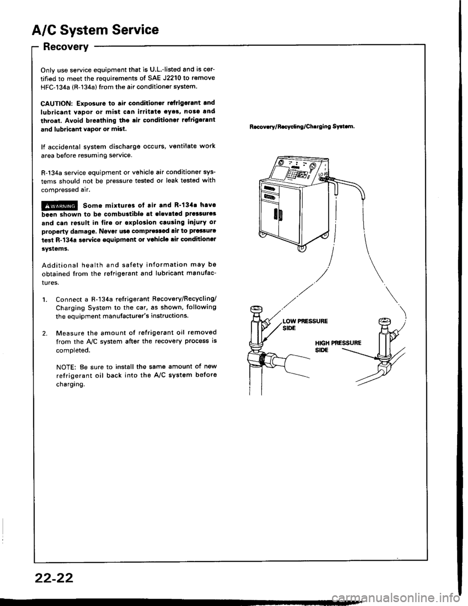
'1. Connect a R-134a refrigerant Recovery/Recycling/
Charging System to the car, as shown, following
the equipment manufacturer's instructions.
2. Measure the amount of refrigerant oil removed
from the A/C system after the recovery process is
comoleted.
NOTE: Be sure to install the same amount of new
refrigerant oil back into the A/C system befote
charging.
R.cov.rylR.cycling/Ch.rging sy.t m.
Pf,ESSUFE
22-22