brake fluid ACURA INTEGRA 1994 Service Repair Manual
[x] Cancel search | Manufacturer: ACURA, Model Year: 1994, Model line: INTEGRA, Model: ACURA INTEGRA 1994Pages: 1413, PDF Size: 37.94 MB
Page 40 of 1413
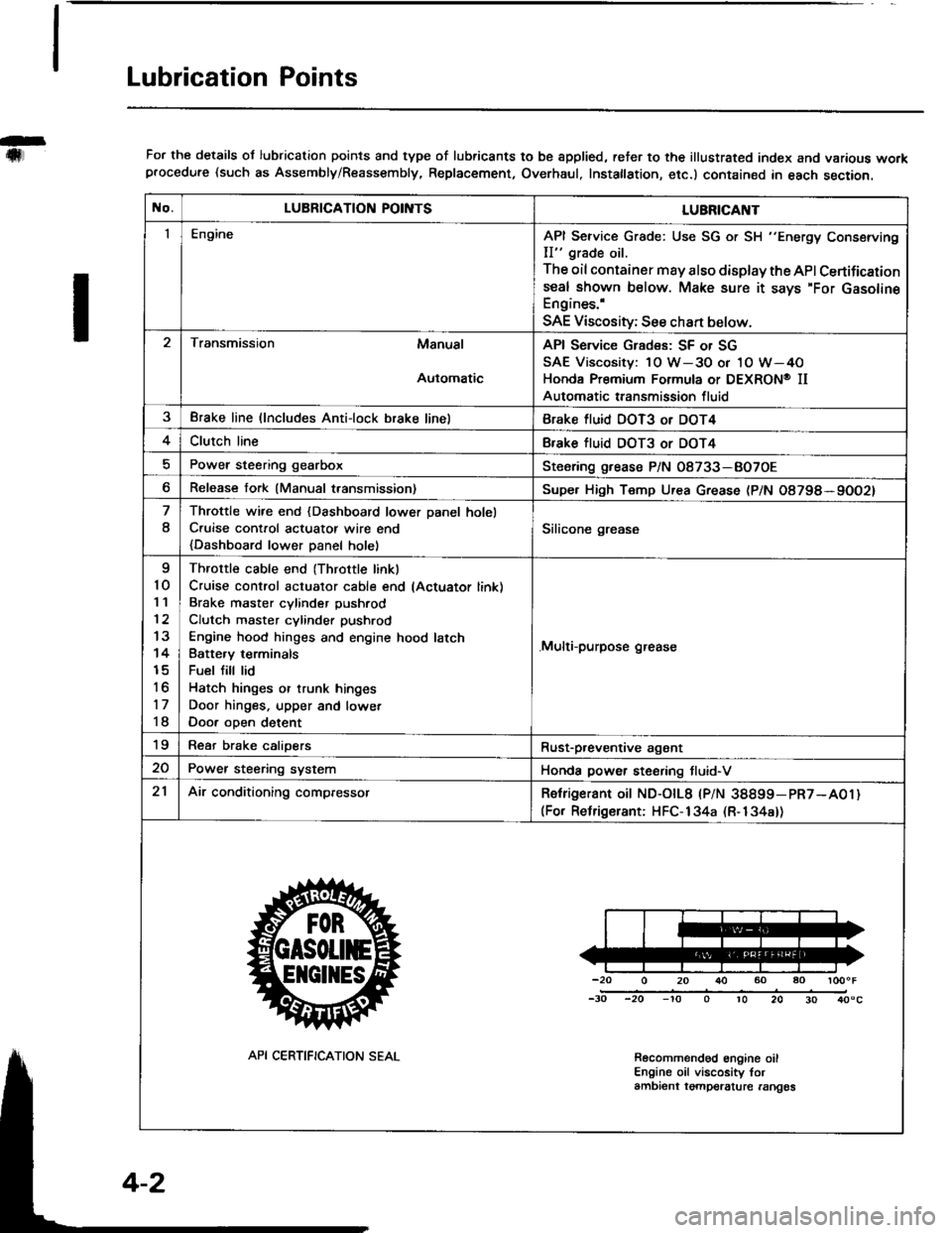
Lubrication Points
For the details ol lubrication points and type of lubricants to be spplied, reter to the illustrated index and various workprocedure (such as Assembly/Reassembly, Replacement, Overhaul, Instatlation, etc.) contained in each section.
No.LUBRICATION POII\ITSLUBRICAI\IT
IEngineAPI Service Grade: Use SG or SH "Energy Conserving
II" grade oil.
The oil container may also display the API Certifications€al shown below. Make sure it says'For GasolineEngines.'
SAE Viscosity; See chan below.
Transmission Manual
Automatic
API Service Grades: SF or SG
SAE Viscosity: 1O W-3O or 1O W-4O
Honda Premium Formula or DEXRON@ II
Automatic transmission fluid
3Brake line (lncludes Anti-lock brake linelBrake fluid DOT3 or DOT4
4Clutch lineBfake tluid DOT3 or DOT4
Power steering gearboxSteoring grease P/N 08733-BO7OE
Release fork (Manual transmission)Supe. High Temp Urea Grease (P/N O8798*9OO2)
8
Throttle wire end {Dashboard lower Danel holel
C.uise cont.ol actuatot wire end
{Dashboard lower Danel holel
Silicone grease
I
10'I '�l
12
13
14
15
to
17
18
Throttle cable end (Throttle linkl
Cruise control actuator cable end lActuator link)
Brake master cvlinder Dushrod
Clutch master cylinder pushrod
Engine hood hinges and engine hood latch
Batte.v terminals
Fuel fill lid
Hatch hinges or trunk hinges
Door hinges. upper and lowet
Door oDen detent
.Multi-purpose grease
19Rear brake calioersRust-p,eventive agant
20Power steering systemHonda power steering tluid-V
21Air conditioning compressorRetrigerant oit ND-otL8 |PlN 38899-pR7-A01)(For Relrigerant: HFC-134a (R-134a))
-20 0 20 r}() 60 ao loooF
-30 -20 -'to o 10 20 30 40"c
Recolnmendod engine oilEngine oil viscosity torambient tgmpelalure rangos
API CERTIFICATION SEAL
Page 335 of 1413
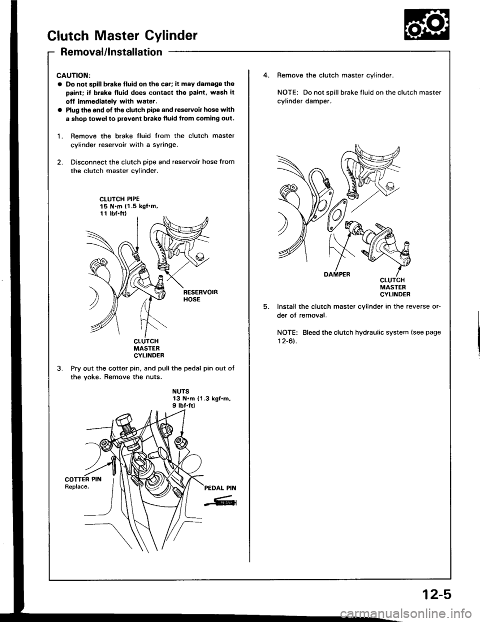
Clutch Master Cylinder
Removal/lnstallation
CAUTION:
a Do not sgill b.ake lluid on the car; it may damags the
painl; it biake fluid does contact tha paint. wash it
otf immediately with water.
a Plug lhe end ot the clutch pips and r€servoil hose with
a shop towel to prsvent blake fluid ttom coming out.
1. Remove the brake fluid from the clutch master
cylinde. reservoir with a syringe.
2. Disconnect the clutch oioe and reservoir hose from
the clutch master cvlinder.
CLUICH PIPE15 N'm {1.5 kgl.m,1 1 tbf.ftl
CLUTCHMASTERCYLINDER
Pry out the cotter pin. and pull the pedal pin out ot
the yoke. Remove the nuts.
NUTS13 N.m {1.3 kgf.m,9 lbt.frl
Remove the clutch master cylinder.
NOTE: Do not spill brake fluid on the
cylinder damper.
OAMPERCLUMAIcYL
Install the clutch master cylinder in
der of removal.
NOTE: Bleed the clutch hydraulic s\
12-61.
clutch master
CLUTCHMASTERCYLINDER
!l rn Ine reverse or-
c system (see page
12-5
Page 336 of 1413
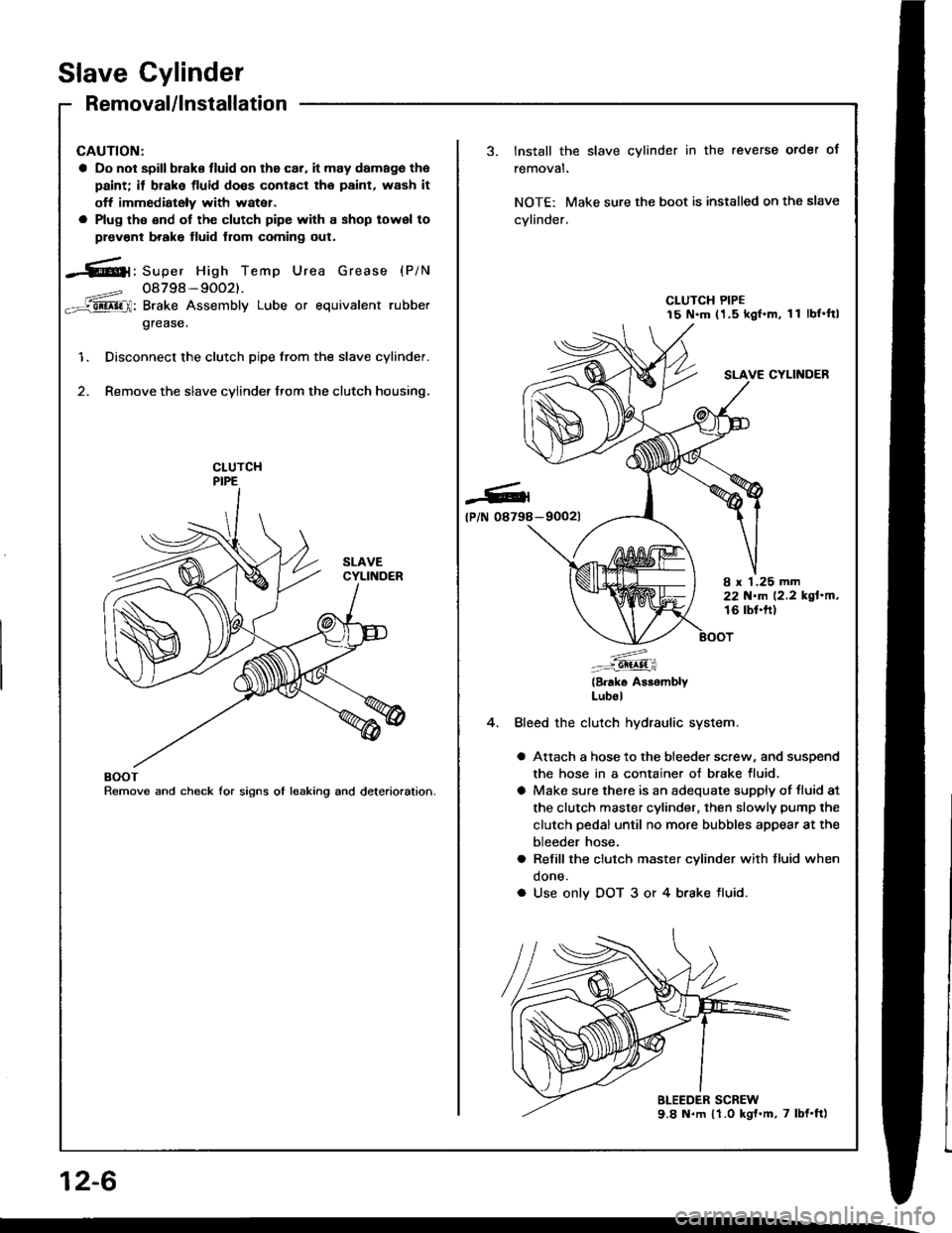
Slave Cylinder
Removal/lnstallation
CAUTION:
a Do not spill brake tluid on the car. it may damago tho
paint; it brake tluid doos conlacl tho paint, wash it
off immediately with watei.
a Plug tho €nd of the clutch pipe with a shop lowsl to
plevcnt b.ake fluid from coming out.
-61, Super High Temp Urea Grease {P/N
08798-9002).
: Brake Assembly Lube or equivalent rubber
grease.
Disconnect the clutch pipe from the slave cylinder.
Remove the slave cylinder from the clutch housing.
'1.
BOOTRemove and check for signs ol leaking and deterioration.
Install the slave cylinder in the reverse order ol
removat.
NOTE: Make sure the boot is installed on the slave
cylinder.
CLUTCH PIPE15 N.m (1.5 kgf.m, 11 lbf'ftl
SLAVE CYLINOER
-90021-Cl
tP/N 08798
8 x 1.25 mm22 N.m 12.2 kgl'm,16 rbt'ft)
4.
:^....:: Gil^lt i
(Brake A$embryLubol
Bleed the clutch hydraulic system.
a Attach a hose 1o the bleeder screw, and suspend
the hose in a container oJ brake fluid.
a Make sure there is an adequate supply of tluid at
the clutch master cylinder. then slowly pump the
clutch pedal until no more bubbles appear at the
bleeder hose.
a Refill the clutch master cylinder with fluid when
done.
a Use only DOT 3 or 4 brake tluid.
12-6
Page 393 of 1413
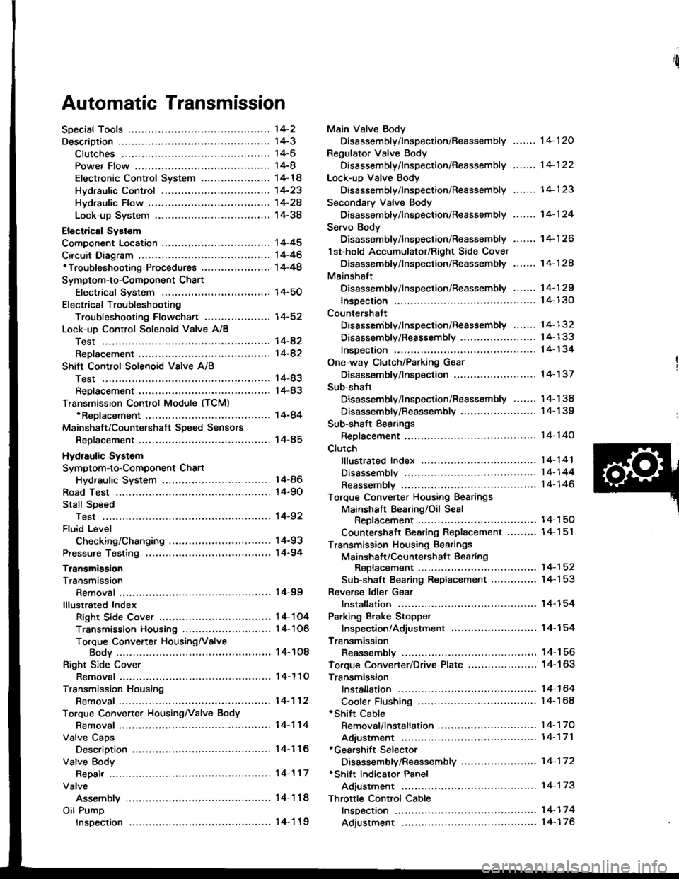
Automatic Transmission
'l4-2
14-3't 4-6
14-8
14-14
14-23
Hvdraulic Flow ...--...... 14-24
Lock-up System ........ 14-38
Eloctrical Systom
Component Location ............,...,................ I 4-45
Circuit Diagram ............. 14-46'Troubleshooting Procedures ........,..........., l4-48
Symptom-to-Component Chart
Electrical System ...... 14-50
Electrical Troubleshooting
Troubleshooting Flowchart .................... 14-52
Lock-uo Control Solenoid Valve A/8
Test .................. --.... \4-82
ReDlacement ,...,...,..,. 14-82
Shift Control Solenoid Vslve A/B
Test .................. ...... 14-83
Reolacement .............. 14-83
Transmission Control Module (TCM)*ReDlacement ........... 14-84
Mainshalt/CountershaJt SDeed Sensors
Reolacement ............. 14-85
Hydraulic Systom
Symptom-to-Component Chart
Hydraulic System
Road Test
Slall Speed
Test ..................
Fluid Level
Checking/Changing
Pressu.e Testing
Transmission
Transmission
Removal ............. ...... 14-99
lllustrated Index
Right Side Cover .................................. 1 4- 1 04
Transmission Housin9 ..................,,....... I 4-1 06
Torque Converter HousingNalve
Body .................. ... 14- 1O8
Right Side Cover
Removal ............. ...... 14-110
Transmission Housing
Removal ............. .-..-. 14-112
Torque Convener HousingNalve Body
Removal ............. ...... 14-114
Valve Caps
Description ................ 14-116
Valve Body
Repair ................ ...-.. 14-117
Valve
Assembly ...........
Oil Pump
Main Valve Body
Disassembly/lnspection/Reassembly
Regulator Valve Body
Disassembly/lnspection/Reassembly
Lock-up Valve Body
Disassembly/lnspection/Reassembly .......
Secondary Valve Body
Disassembly/lnspection/Reassembly .......
Servo Body
Disassembly/lnspection/Reassembly .......
1st-hold Accumulator/Right Side Covet
Oisassembly/lnspection/Reassembly .,..,..
Mainshaft
Disassembly/lnspection/Reassembly -.. -... 1 4- 1 29
lnsDection ................. 14- 130
Countershaft
Disassembly/lnspection/Reassembly ....... 14-132
Disassembly/Reassembly ....................... 1 4-1 33
lnsDection ................. 14-134
One-way Clutch/Parking Gear
Disassembly/lnspection .................... -.. -. 1 4-137
Sub-shaft
Disassembly/lnspection/Reassembly ....... 14-138
Disassemblv/Reassemblv ....................... 1 4-1 39
Sub-shaft Bearings
Replacement ............. l4-140
Clutch
fllustrated lndex ................. -..-...-.......... 14-1 41
Disassembly ,,,.,,........ 14-144
Reassembly .............. 14-146
Torque Converter Housing Bearings
Mainshaft Bearing/Oil Seal
Reolacement ......... 14-1 50
Countershaft Bearing Replacement .......,, 14-1 5l
Transmission Housing Bearings
Mainshsft/Countershaft Bearing
Repfacement ...-..-..14-152
Sub-shaft Bearing Replacement .............. 1 4-1 53
Reve.se ldler Gear
lnstallation ................ 14-154
Parking Brake Stopper
lnspection/Adjustment ..........................'14-'154
Transmission
Reassemblv .............,. .14_156
Toroue Converter/Drive Plate ..,..,............... 1 4- 1 63
Transmission
14-120
14-122
14-123
14-124
14-126
14-124
14-86
14-90
't4-92
14-93
14-94
lnstallation
Cooler Flushing'Shitt Cable
Removal/lnstallation ..............................
Adiustment ...-..-......-. 14-'171*Gearshift Selector
Disassembly/Reassembly .....................,. 1 4-17 2*Shift Indicator Panel
Adjustment -..........-...14-173
Throttle Control Cable
fnspection .......,..,...... 14-17 4
Adjustment .............. 14-176
14-164
14-168
14-'t 7 0
Inspection
Page 484 of 1413
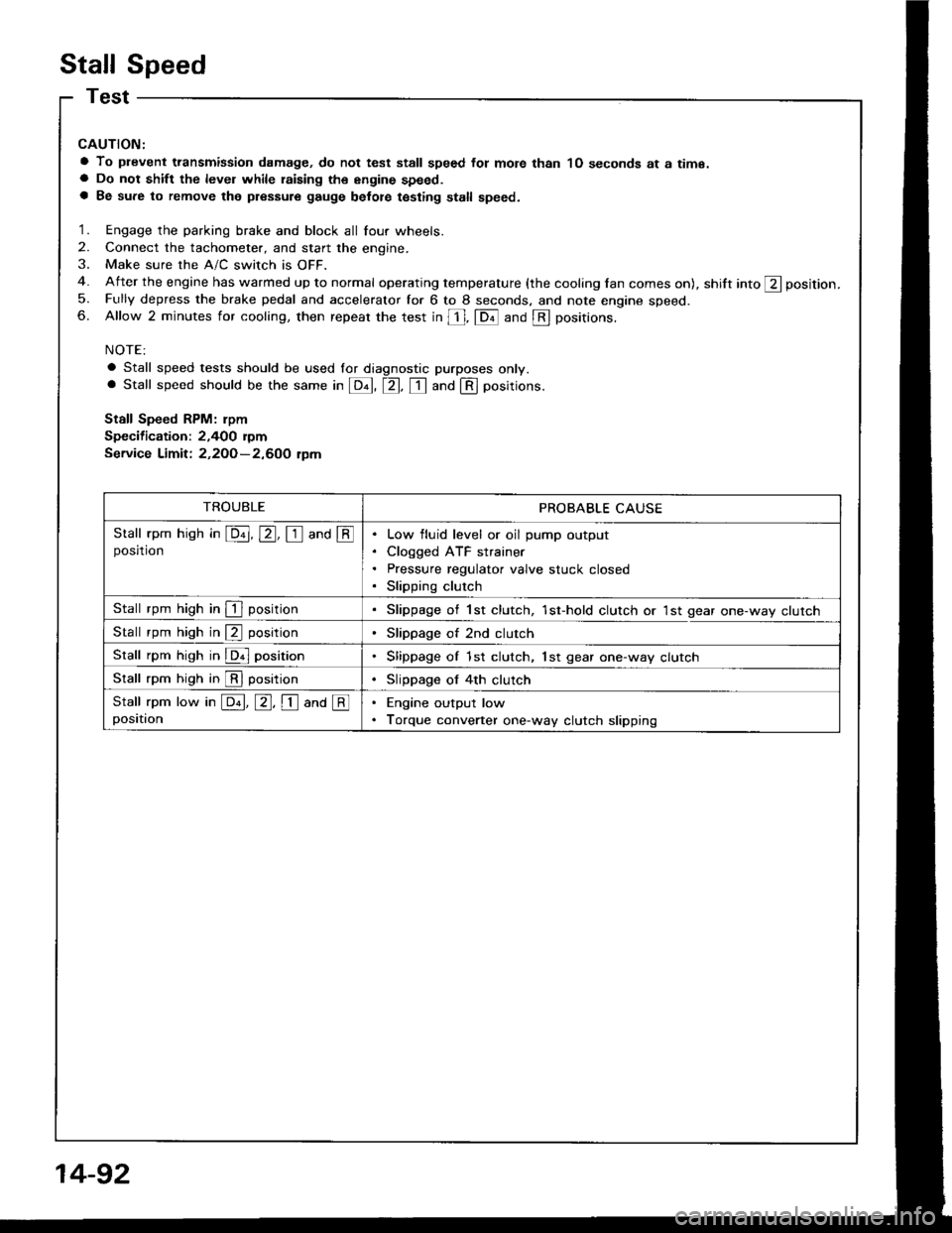
Stall Speed
CAUTION:
a To plevent transmission damage, do not test stall speed fot mote than 1O seconds at a time.a Do not shift the level while raising th€ engine speed.a Be sure to remove the pressure gauge belot€ testing stall speed.
1. Engage the parking brake and block all four wheels.
2. Connect the tachometer, and start the engine.
3. Make sure the A/C switch is OFF.
4. After the engine has warmed up to normal operating temperature (the cooling lan comes on), shift into ft position.
5. Fully depress the brake pedal and accelerator for 6 to 8 seconds. and note engine speed.6. Allow 2 minutes for cooling, then repeat the test in [, fDil and @ positions.
NOTE:
a Stall speed tests should be used lor diagnostic purposes only.. Stall speed should be the same in E, tr. tr and @ positions.
Stall Speed RPM: rpm
Specification: 2,400 rymService Limit: 2,2OO-2,600 tpm
TROUBLEPROBABLE CAUSE
Stall rpm hish in E, E, I and @posrtronLow fluid level or oil pump output
Cloqged ATF strainer
Pressure regulator valve stuck closed
Slipping clutch
Stall rpm high in I positionSlippage of 1st clutch, 1st-hold clutch or 1st gear one-way clutch
Stall rpm high in @ positionSlippage of 2nd clutch
Stall rpm high in @ positionSlippage of 1st clutch, lst gear one-way clutch
Stall rpm high in @ positionSlippage of 4th clutch
Stall rpm low in E, E, I ana @positionEngine output low
Torque converter one-way clutch slipping
14-92
Page 486 of 1413
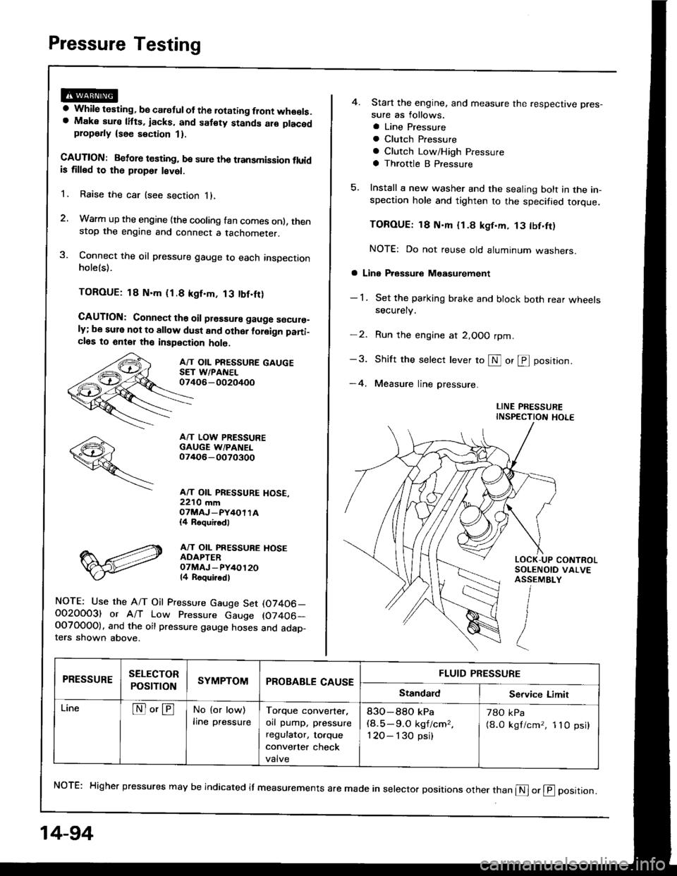
Pressure Testing
a While testing, be caretul of the rotating flont wheels.a Make aura litts, jacks, and sat€ty stands alo placedplop6rly {see section 1}.
CAUTION: Betore t€sting, be sure the transmission fluidis tilled to rh6 ploper l€vet.
1. Raise the car (see section i),
2. Warm up the engine {the cooling fan comes onl, thenstop the engine and connect a tachometer.
3. Connect the oil pressure gauge to each inspectionholels).
TOROUE: 18 N.m (1.8 kgf.m, 13 tbf.fr)
CAUTION: Connect ths oil prsssure gauge s€cur€_ly; be sule not to allow dust and other foleign pani_cl6s to 6nt€1 th€ inspection holo.
A/T OIL PRESSURE GAUGESET WPANEL07406-002oi+oo
A/T LOW PRESSUREGAUGE W/PANEL07/rO6-0O70300
A/T OIL PRESSURE HOSE,22'10 mmOTMAJ_PY4OI TA{4 Roquirod)
A/T OIL PRESSUBE HOSEADAPTEROTMAJ - PY/+O12014 Roqui.odl
NOTE: Use the A/T Oil Pressure Gauge Set (07406_O02OOO3) or A/T Low Pressure Gauge (07406-OOTO0OO). and the oil pressure gauge hoses and adap_ters shown above.
14-94
4. Start the engine, and measure the respective pres-
sure as follows.
a Line Pressure
a Clutch Pfessure
a Clutch Low/High Pressure
a Throttle B Pressure
5. Install a new washer and the sealing bolt in the in-spection hole and tighten to the specified torque.
TOROUE: 18 N'm {1.8 kgf.m, 13 tbf.ft)
NOTE: Do not reuse old aluminum washers.
a Line Pressure M€asurement
- 1 . Set the parking brake and block both rear wheelssecurely.
-2. Run the engine at 2,OOO rpm
-3. Shift the selecr lever to S or @ position.
-4. Measure line pressure.
LINE PRESSUREINSPECTION HOLE
NoTE: Higher pressures may be indicated it measurements are made in selector positions other than @ or @ position.
PRESSURESELECTOR
POStTTONSYMPTOMPROBABLE CAUSEFLUID PRESSURE
StandardService Limit
LineNo'ENo (or low)
lrne pressureTorque converter,
orl pump, pressure
regulator, to.que
convener check
valve
83O-88O kPa(8.5-9.O kgf/cm,,
120- I 30 psi)
78O kPa
{8.0 kgl/cm,, 1lO psi}
Page 487 of 1413
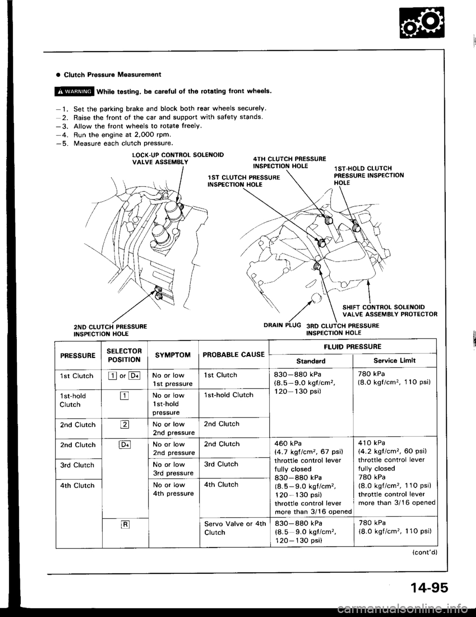
a Clutch Pressuro M€asur€ment
@ wtit" testing, be careful ot the rotating front wheols.
1. Set the parking brake and block both rear wheels securely.
2. Raise the front of the car and support with safety stands.
-3. Allow the front wheels to rotate freely,
-4. Run the engine at 2,OOO rpm.-5. Measure each clutch Pressure.
LOCK.UP CONTNOL SOLENOIDVALVE ASSEMBLY
INSPECTION HOLE
SELECTOB
POST ONSYMPTOMPROBABLE CAUSE
FLUID PRESSURE
rl|E!!UltEStandardService Limit
1st ClutchEo'ENo or low
lst Pressure
1st Clutch83O-880 kPa
(8.5-9.O kgf/cm',
120- 130 psi)
78O kPa
{8.O kgf/cm'�, 11O psi)
l st-hold
ClutchtrNo or low
1st-hold
pressure
1st-hold CIutch
2nd ClutchaNo or low
2nd pressure
2nd Clutch
2nd ClutchENo or low
2nd pressure
2nd Clutch460 kPa
|'4.7 kgt lcm2, 67 psil
throttle control lever
fully closed
830-880 kPa
(8.5 - 9.0 kgt/cm'�,
120- l30 psi)
throttle control lever
more than 3/16 opened
4'l o kPa
(4.2 kgt/cm'�, 60 psi)
throttle control lever
fully closed
78O kPa(8.O kgf/cm'�, 1 1O psi)
throttle control lever
more than 3/16 opened
3rd ClutchNo or low
3rd pressure
3rd Clutch
4th ClutchNo or low
4th pressure
4th clutch
EServo Valve or 4th
Clutch
830-880 kPa
(8.5 9.0 kqf/cm'�,
120- 130 psi)
780 kPa
(8.0 kgf/cm'�, 1 1O psi)
(cont'd)
14-95
Page 557 of 1413

20. Connect the vehicle speed sensor (VSS), mainshatt
speed sensor and counterchalt speed sensor con
nectors.
VEHICLE SPEED SEiISORCONNECTOR
21. Connect the lock-uD control solenoid valve connec-
tor and shift control solenoid valve connector. then
clamp the lock-up control solenoid harness with the
harness stay.
22. Connect the transmission ground cable.
LOCK-UP CONTROLSOLENOID VALVE HARNESS STAY
23. Connect the starter cable to the starter motor, and
install the cable holder.
NOTE: When installing the starter motor cable,
make sure that the crimped side of the ring terminal
is facing out (see section 23).
CABLEHOLDER
6x 1.0 mm'12 N.m (1.2 kgf'm,8.7 lbt.tl)
24.
N.mlO.9 ksr.m, 7 tbr-rtt
STARTER CAELE
Install the air cleaner housing assembly and intake
arr oucl.
AIR CLEANER HOUSINGASSEMBLYINTAKE AIRDUCT
25.
26.
24.
29.
30.
Retill the transmission with ATF(see page '14-93).
Connect the battery positive ( + ) and negative ( - )
cables to the battery.
Start the engine. Set the parking brake, and shift the
transmission through all gears three times.
Check shitr cable adjustment as described on page
14-171 .
Check that front wheel alignment (see section 18).
Let the engine reach operating temperature (the cool-
ing tan comes on) with the transmission in S or @position, then turn it off and check the fluid level.
31. Road test as described on page 14-9o and 91.
14-167
Page 603 of 1413
5.
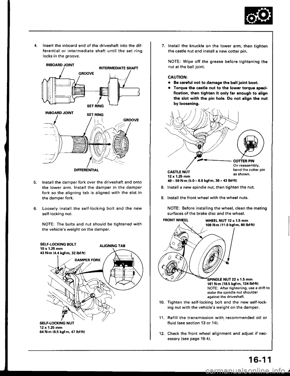
Insert the inboard end of the driveshaft into the dif-
ferential or intermediate shaft until the set ring
locks in the groove.
INBOARD JOINT
INAOARD JOINT
OIFFERENTIAL
Install the damper fork over the driveshaft and onto
the lower arm. Install the damper in the damper
fork so the aligning tab is aligned with the slot in
the damper fork.
Loosely install the self-locking bolt and the new
self-locking nut.
NOTE: The bolts and nut should be tightened with
the vehicle's weight on the damper.
ALIGNING TAB
SELF.LOCKING NUT12x 1.25 mm64 N.m (6.5 kgt m, 47 lbf.ftl
GROOVE
SELF.LOCKING BOLT10 x 1.25 mma:' N.m lir,4 kgt m, 32 lbf.ftt
1.Install the knuckle on the lower arm, then tighten
the castle nut and install a new cotter pin.
NOTE: Wipe off the grease before tightening the
nut at the ball joint.
CAUTION:
. B€ careful not to damago tho ball ioint boot.
. Torqu€ tho castle nut to ths lower torquo 3paci.
fication, then tighlon it only tar snough to slign
the slot with th€ pin hole. Do not align tho nut
by loossning,
COT1ER PIf{On reassembly,bend the cotter pin
as shown.
9.
CASTLE NUT12 x 1.25 rnma9 - 59 N.m 15.0 - 6.0 kgt.m, 36 - a:t lbtftl
Install a new spindle nut, then tighten the nut,
Install the front wheel with the wheel nuts.
NOTE: Before installing the wheel, clean the mating
surfaces of the brake disc and the wheel.
FRONT WHEELWHEEL NUT 12 x 1.5 mm108 N.m (11.0 kgf.m,80lbtft,
8.
1 '�I.
10.
NUT 22 x 1.5 mm181 N m 118.5 kgl'm, 134lbt'ftlNOTE: Altor tightening, use a drift to
stake the sPindle nut shoulderagainst the driveshaft
Tighten rhe self-locking bolt and the new self-lock-
ing nut with the vehicle's weight on the damper.
Refill the transmission with recommended oil or
fluid (see section 13 or 14).
Check the front wheel alignment and adjust if nec-
essary {see page 18-4).
12.
16-1 1
Page 1126 of 1413

Connector ldentification and Wire Harness Routing
ABS Modulatol Unit Wile Harness
Engine Compartmont Wile Hatnaaa
Connoctor or
Torminal
Numbor ot
CaviiieELocationConnocta tooies
Ltol
c162
c163
c164
c165
c166
c't 67
c168
't4
2
2
Right side of engine comPartment
ABS modulator unit
ABS modulator unit
ABS modulator unit
ABS modulator unit
ABS modulator unit
ABS modulator unit
ABS modulator unat
Main wire harness (c21 1)
ABS Dressure switch
ABS right Jront solenoid (OUT)
ABS right front solenoid (lN)
ABS rear solenoid (OUT)
ABS rear solenoid llN)
ABS le{t front solenoid {OUT)
ABS left tront solenoid (lNl
Connector or
Tolminal
Numbd of
CaviliesLocationConnocta tot{oioE
c301
c302
c303
c304
c305
c306
c307
c308
c309
c310
c31 1
c312
c313
c314
c315
c316
c317
c318
c319
c320
20
20
1
2
14
2
1
1
2
4
2
2
1
2
2
5
Behind left kick Panel
Behind left kick panel
Behind lett kick Panel
Left side of engine compartment
Left side of engine comPartment
Left side of engine comPartment
Left side o{ engine comPartment
Left side of engine comPartment
Left side of engine compartment
Lelt side oJ engine comPartment
Middle of engine comPartment
Left side of engine comPartment
Left side oJ engine comPafiment
Behind leJt headlight
Behind left headlight
Behind left headlight
Behind left corner ot front
bumper
Behind lett corner ot front
DUmper
Behind left corner of ftont
DUmper
Behind left cornet of front
DUmper
Main wire harness (C4231
Main wire harness (C424)
Front fog light sYstem
Engine wire harness (C126)
Engine wire harness (C 127)
Test tachometer connector
Daytime running lights resistor
Windshi€ld wiper motot
Brake fluid level sensor ( + |
Brake fluid level sensor (- )
Power steering pressure (PSPI
Lett front wheel sensor
Cruise control actuator
Left headlight (Low beam)
LeJ-t headlight (High beam)
Front fog light system
Windshield washer motor
switch
Rear window washer motor
Left front side matker light
Left front tu.n signal/parking lights
USA
ABS
Option
Canada
Option
G301Lett side of engine comPartmentBody ground, via engine comPart-
ment wire harness
23-20