height ACURA INTEGRA 1994 Service Repair Manual
[x] Cancel search | Manufacturer: ACURA, Model Year: 1994, Model line: INTEGRA, Model: ACURA INTEGRA 1994Pages: 1413, PDF Size: 37.94 MB
Page 13 of 1413
![ACURA INTEGRA 1994 Service Repair Manual Lift and Support Points
Lift
Wh€n heavy 16ar compon€nts such aa susponsion, luel tank, spale tile and hatch ale to
il]iii6iliieigltt in the tuggage area bsfore hoisting. When substantial woight is ACURA INTEGRA 1994 Service Repair Manual Lift and Support Points
Lift
Wh€n heavy 16ar compon€nts such aa susponsion, luel tank, spale tile and hatch ale to
il]iii6iliieigltt in the tuggage area bsfore hoisting. When substantial woight is](/img/32/56982/w960_56982-12.png)
Lift and Support Points
Lift
Wh€n heavy 16ar compon€nts such aa susponsion, luel tank, spale tile and hatch ale to
il]iii6iliieigltt in the tuggage area bsfore hoisting. When substantial woight is lemoved from ths
b€ removod, plac6
l€ar ol th€ car, ths
cantor of gravity may chango and can cause the cal to tip folward on the hoist'
NOTE: Since each tire/wheel assembly weighs approximately 14 kg (30 lbs), placing the front wheels in trunk can assist
with the weight distribution.
1. Place the lift blocks as shown
2. Raise the hoist a lew inches (centimeters) and rock the car to be sure it is firmly supported.
3. Raise the hoist to full height and inspect lift points for solid support.
FRONT SUPPORT POINTLIFT BLOCKSBEAR SUPPORT POINT
1-9
Page 19 of 1413

Standards and Service Limits
Cylinder Head/Valve Train (B188t enginelSecti6
*: Measured between the camshaft and rocker arm.
NH: NIHON HATSUJO manufactur€d valve spring
CH: CHUO HATSUJO manufacturod valve sDrino
- Declron
MEASUREMENTSTANDARD {NEWI '
SERVICE LIMIT
Compression250 rpm and wide open th.ottl€ Nominal
kPa (kgflcm?, psi) Minimum
Maximum variation
1,370 (14.0, 199)
930 (9.5, 140)
200 t2.0,2a)
Cylinder h.adW6rpage
Heightr31.95- 132.05 (5.195 - 5.199)
0.05 (0.002)
CamshaftEnd play
Camshaft-to-holder oil clearance
Total runout
Cam lobe height tN
EX
0.05 - 0.15 (0.002 - 0.0061
0.030 - 0.069 10.0012 - 0.0027)
0.03 (0.001) max.
33.7 16 11 .327 1l
33.528 (1.3200)
0.5 (0.02)
0.1s {0.006)
0.04 (0.002)
Valve clearance (Cold)* lN
EX
Valve stem O.D. tN
EX
Stem-to-guide clearance lN
EX
0.08 - 0.12 {0.003 - 0.005)
0.'r 6 - 0.20 (0.006 - 0.008)
6.580 - 6.590 (0.2591 - 0.2594)
6.550 - 6.s60 (0.2579 - 0.2583)
0.02 - 0.0s (0.001 - 0.002)
0.05 - 0.08 (0.002 - 0.003)
6.s5 (0.258)
6.52 (0.257)
0.0810.003)
0.11 (0.004)
width tN
EX
Stem instslled height tN
EX
r.25 - 1.55 (0.049 - 0.061)
1.25 - 1.55 {0.049 - 0.061)
40.765 - 41.235 (1.6049 - 1.6234)
12.763 - 43.235 t1,6a37 - 1.7022)
2.0 t0.08)
2.0 (0.08)
41.485 (1.6333)
43.485 (1.7120)
Valve springFree length {Reference} lN
EX NH
CH
42.36 (1.668)
47.09 {1.854}
47.08 (1.854)
41.s6 {1.636)
46.27 tl.A22l
46.21 l1.a22l
Valv6 guideLu. lN
EX
Installed height lN
6.61 - 6.63 (0.260 - 0.261)
6.61 - 6.6s (0.260- 0.261)
13.75 - 14.25 {0.541 - 0.561}
r5.75 - 16.25 10.620 - 0.640)
6.65 (0.262)
6.6510.2621
3-2
Page 21 of 1413

Standards and Service Limits
Cylander Head/Valve Train (B18Cl enginelSection 6
': M€asured betwoon the camshatt and rcc(er srm.
NH: NIHON HATSUJO manufacture v6lve spring
CH: CHUO HATSUJO manufscturo v6lve spring
MEASUBEMENTSTA]TDARD INEWISERV|C€ UM|T
Compr€6sion250 rpm and wide op€n throttle Nomin6l
kPa lkgl/cmr, psi) Minimum
Maximum variation
1,860 (19.0, 270)
930 (9.s, 140)
200 t2.o,2a)
Cylind6r hoadWarpage
H6ight'r41.95 - 1C2.05 (5.s89 - 5.593)
0.05 {0.002)
C.mshsftEnd play
Camshaft-to-holdsr oil clearance
Total runout
Cam lobo height lN Primery
Mid
Socondary
EX Primary
Mid
Secondary
0.05 - 0.1s (0.002 - 0.006)
0.050 - 0.089 (0.0020 - 0.0035)
0.015 (0.0006) max.
33.411{1.3154)
36.377 tl.13221
34.547 (1.3601)
33.1110.3036)
35.72011.4063)
34.381 {1.3536)
0.5 (0.02)
0.15 {0.006)
0.03 (0.001)
Valvo clorrance lcoldl* lN
EX
Valve stem O.D. lN
EX
Stom-to-guid6 clerrsnco lN
EX
0.15 - 0.19 {0.006 - 0.007}
0.17 - 0.21 (0.007 - 0.008)
5.475 - 5.48s (0.2156 - 0.21591
5.450 - 5.460 (0.2146 - 0.21s0'
0.025 - 0.055 {0.00'10 - 0.0022}
0.050 - 0.080 (0.0020 - 0.0031)
5.11510.21441
s.420 {0.2134)
0.08 10.003)
0.11{0.(x)4)
Valvo seatWidth tN
EX
Sr6m installed h€ight lN
EX
1.25 - 't.5s (0.049 - 0.06't)'1.25 - 1.s5 {0.049 - 0.061)
37.465 - 37.935 ('1.4750 - 1.4935)
37.16s - 37.635 t1.4632 - 1.4817)
2.0 (0.08)
2.0 (0.08)
38.185 (1.5033)
37.885 (1.491s)
Valv€ BpringFre6length (Roferenca) lN Outer
Inner NH
CH
EX NH
CH
41.05 (r.6161
36.'16 {1.4241
36.19 t1.425)
41.96 (1.652)
41.94 {1.651)
40.26 (1.585)
35.30 (1.390)
35.30 (1.390)
40.95 (1.612)
40.95 (1.612)
Valve guidol.D. tN
EX
Instslled hoight lN
EX
5.51 - 5.53 (0.217 - 0.218)
5.5r - 5.53 {0.2r7 - 0.218)
12.55 - r3.0s (0.494 - 0.514)
12.55 - 13.05 (0.494 - 0.s14t
5.55 (0.219)
5.5s {0.219}
Rock€r ermArm-to-shaft clearance lN
EX
0.025 - 0.0s2 {0.0010 - 0.0020)
0.025 - 0.0s2 (0.0010 - 0.0020)
0.08 (0.003)
0.08 (0.003)
3-4
Page 24 of 1413
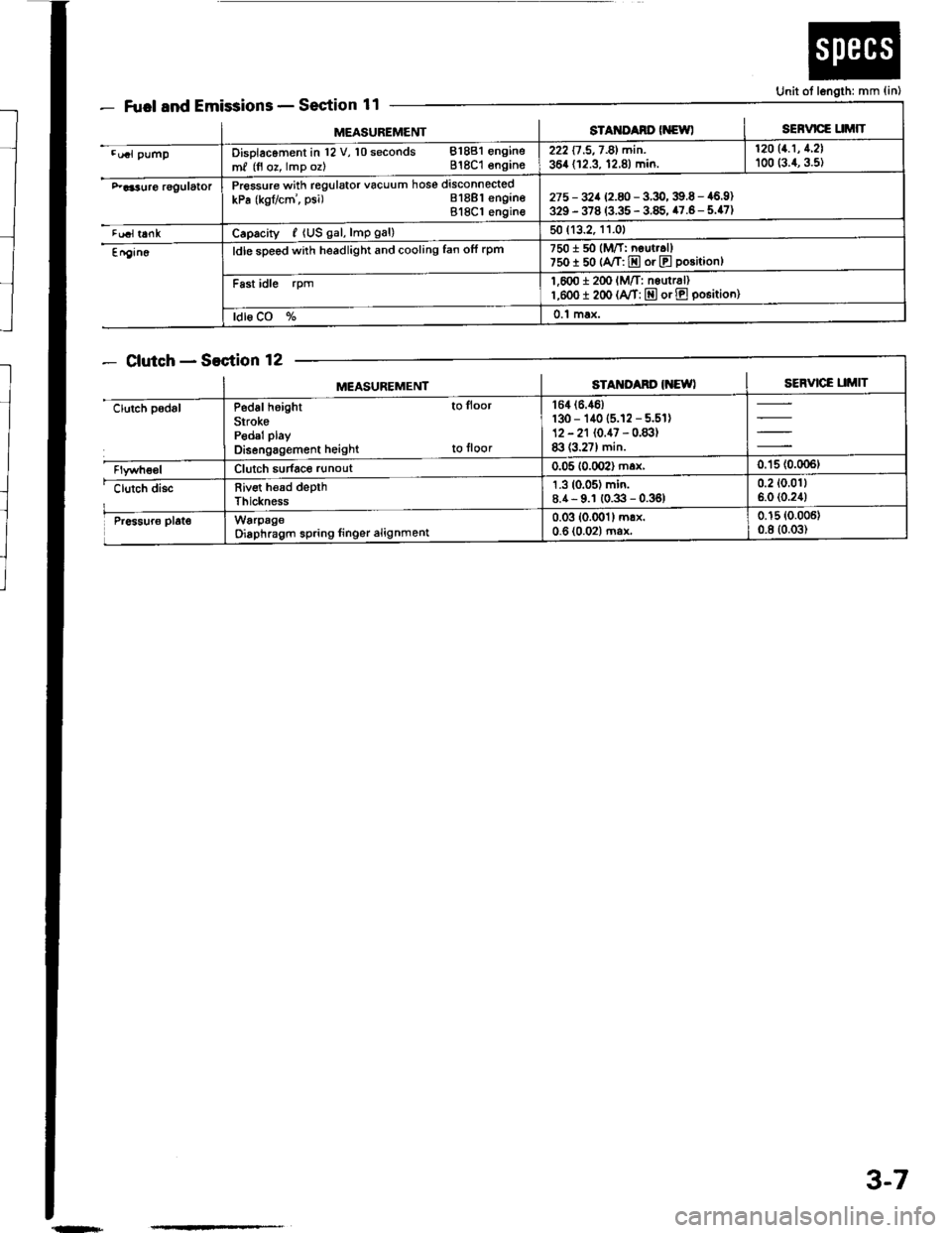
Fuel and EmissionsSection 11
ClutchSection 12
Unit ot length: mm {in)
MEASUREMENTsTAt{ItAno (NewlSERVICE UMIT
.u.l pumpDisolacoment in l2 V, 10 seconds 81881 engine
m, (fl oz, lmp oz) 818C1 engins222 17 .5,7 -81 min. | 12011.1' 1'21
364 (12.3, 12.8) min. I too (:.1, g.st
F aa3uro rggulatorPressure with regulator vacuum hose disconnected
kPa (kgflcm', psi) Bl8Bl engineBl8Cl engin€275 - 32a 12.8 -3.9,39.6 - 46.9)329 - 378 (3.35 - 3.85, 47.6- 5.47)
tualt6nkCaprcity, {US gal, lmp gal)50 (13.2, 11.01
En9in6ldle sDeed with headlight and cooling fan ofi rpm7501 50 (M/T: neut..ll750I 50 {A/T: E or E position}
Fast idle rpm1,600 i 2(x' lM/T: nsurr6l)l,eoo I 200 (A/T: E or E po6itioo)
ldl6 CO %0.1 max.
MEASUREMENTSTAM'Ad' IiEWISERVICE UMIT
clutch padslP6d6l height to lloor
SirokePedal play
Disengagement height to floor
164 (6.46)
130 - 140 (5.12 - 5.51)12 - 21 (0.47 - 0.83)83 (3.27) min.
Clutch sudace runout0.05 10.002) max,0.'15 (0.006t
clutch discRiv€t h€ad depthThickness
1.3 (0.05) min.8.4- 9.1 (0.3 - 0.36)0.2 (0.011
6.0 (0.24)
Pr6sur6 plat€WarpageOiaphragm spring linger alignment0.03 (0.001) mrx.0-6 (0.02) ma*0.15 (0.006)
0.8 (0.03)
{n+
3-7
Page 34 of 1413
![ACURA INTEGRA 1994 Service Repair Manual Design Specifications
]TEMMETRICENGLISHNOIES
: vENSTONSOveralllength 3 DOOR
4 DOOR
Ov€rallWidth
Overall Height 3 DOOR
4 DOOR
Wheelbase 3 DOOR
4 DOOR
Track F/R
Ground Clearance
Seating Capacity
4.38 ACURA INTEGRA 1994 Service Repair Manual Design Specifications
]TEMMETRICENGLISHNOIES
: vENSTONSOveralllength 3 DOOR
4 DOOR
Ov€rallWidth
Overall Height 3 DOOR
4 DOOR
Wheelbase 3 DOOR
4 DOOR
Track F/R
Ground Clearance
Seating Capacity
4.38](/img/32/56982/w960_56982-33.png)
Design Specifications
]TEMMETRICENGLISHNOIES
:' vENSTONSOveralllength 3 DOOR
4 DOOR
Ov€rallWidth
Overall Height 3 DOOR
4 DOOR
Wheelbase 3 DOOR
4 DOOR
Track F/R
Ground Clearance
Seating Capacity
4.380 mm
4.525 mm
'1,710 mm
1,335 mm
1,370 mm
2,570 mm
2,620 mm
't,475/1,470 mm
150 mm
Four (3 DOOR)
172.1in
178.1 in
67.3 in
52.6 in
101.2 in
103.1 in
5|8.1/57.9 in
Five (4 DOOR)
,rerght (usA)cross V€hicle Weight Rating {GVWR)3,680lbs
'le,ght {CANADA)Gross Vehicls Weight Rating {GVWR)1,670 kg
:\GINEType81881 engine
818C1 engine
Cylinder Arrangement
Bore and Stroke
Displacement
Compression Ratio
81881
818C1
81881
B18C I
81881
B 18C1
81881
818C1
engrne
engane
engrne
engine
engine
engine
engine
engine
L!brication Systom
OilPump Displacement
Wster Pump Displacement
FuelRequired
81881
B18C 1
81881
B 18C1
91881
engrne
engrne
engine
engine
engine
818C1 engine
Water-cooled, 4-stroke DOHC
gasoline engine
Watercooled, 4-stroke DOHC
VTEC gasoline engine
Inline 4-cylinder, transverse
81.0 x 89.0 mm
81.0 x 87.2 mm
1,834 cm3 (mf )
1,797 cm3 (m{)
3.19 x 3.50 in
3.19 x 3.43 in
112 cu-in
110 cu-in
9.2:1
10.0 : 1
Eelt driven, OOHC 4 valve per cylinder
Belt driven, DOHC VTEC
4 valve per cylinder
Forced and wet sump, trochoid pump
50, {53 US qt, 44 lmp qt)/minute'l
71 f {75 US qt, 62 lmp qt)/minute"
140 f (148 US qt, 123 lmp qt)/minute*!
140 f (148 US qt. 123 lmp qt)/minute*'
UNLEADED gasoline with 86 Pump
Octane Numb€r or higher
Premium UNLEADED gasoline wilh
91 Pump Octane Number or higher
STARTERTypo
NormalOutput
NominalVoltage
Hour Rating
Direction of Rotation
Weight
Gear reduction
1.4 kW
12V
30 seconds
Clockwise as viewed lrom g6ar end
3.7 k9 | 8.3lbs
CLUTCHClutch Type
Clutch Facing Area
M/TSingle plate dry, diaphragm spring
Torq!e converter
203 cm'� I 31 sq-in
TRANSMISSIONTransmission Type M/T
Primary Reduction
Synchronized 5-speed forward, 1 reverse
Electronically controlled
4-speed automatic. 1 rcverse
Diract 1 : 1
'1: At 6,000 engine
'2: At 7,600 engine
rpm
rpm
(cont'd)
3-17
Page 52 of 1413
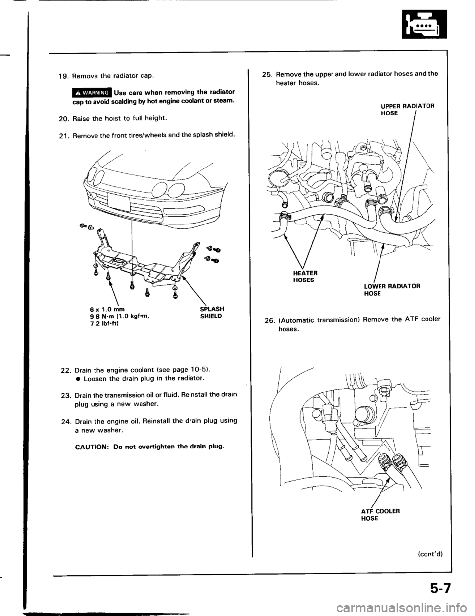
19. Remove the radiator cap.
@@ u"" care whan removing the ladiatol
cap to avoid scalding by hot engine coolant ol ateam.
20. Raise the hoist to full height.
21. Remove the front tires/wheels and the splash shield.
Drain the engine coolant (see page 1O-5).
a Loosen the drain plug in the radaator.
Drain the transmission oil or fluid. Reinstall the dtain
plug using a new washer.
Drain the engine oil. Reinstall the drain plug using
a new wasner.
CAUTION: Do not overtighten tho drain plug.
22.
24.
6 x 1.O mm9.8 N.m (1.0 kgf'm'7.2 tbf.ft)26.
25. Remove the upper and lower radiator hoses and the
heater hoses.
LOWER RADIATORHOSE
(Automatic transmission) Remove the ATF cooler
hoses.
{cont'd)
UPPER RADIATOR
HOSE
5-7
Page 89 of 1413
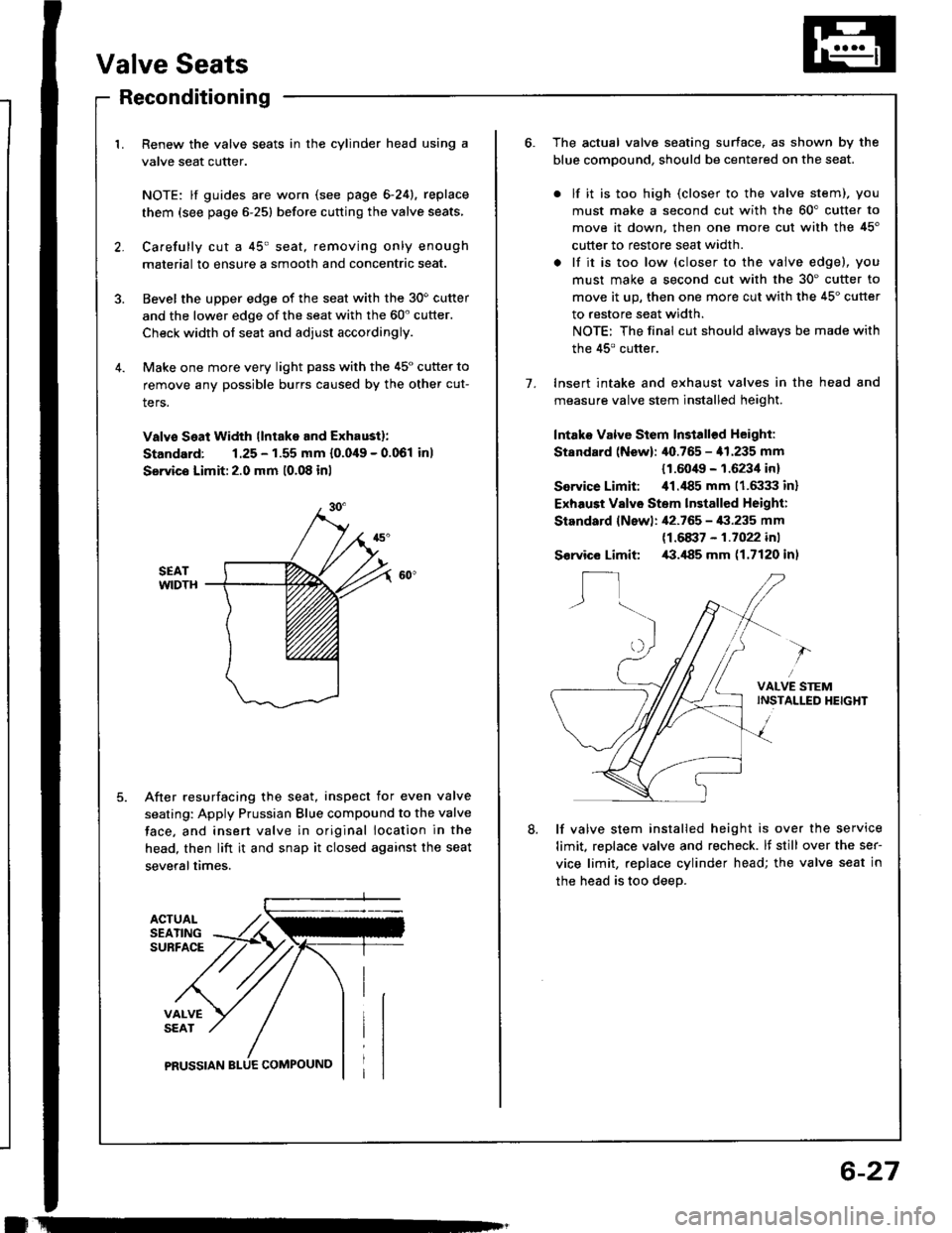
Valve Seats
ACTUALSEATINGSUBFACE
VALVESEAT
PRUSSIAN
Reconditioning
1. Renew the valve seats in the cylinder head using a
valve seat cutter.
NOTE: lf guides are worn (see page 6-24), replace
them (see page 6-251 before cutting the valve seats,
2. Carefully cut a 45' seat, removing only enough
material to ensure a smooth and concentric seat.
3. Bevel the upper edge of the seat with the 30o cutter
and the lower edge of the seat with the 60' cutter.
Check width of seat and adjust accordingly.
4. Make one more very light pass with the 45" cutter to
remove any possible burrs caused by the other cut-
ters.
Valvo Seat Width llntake and Exhaustl:
Standard: 1.25 - 1.55 mm {0.049 - 0.061 inl
Servics Limit:2.0 mm 10.08 inl
SEATWIDTH
After resurfacing the seat, inspect for even valve
seating: Apply Prussian Blue compound to the valve
face, and insert valve in original location in the
head, then lift it and snap it closed against the seat
severaltimes.
!
6-27
7.
The actual valve seating surface, as shown by the
blue compound, should be centered on the seat.
. lf it is too high (closer to the valve stem), you
must make a second cut with the 60" cutter to
move it down, then one more cut with the 45'
cutter to restore seat width.
. lf it is too low (closer to the valve edgel, you
must make a second cut with the 30' cutter to
move it up, then one more cut with the 45" cutter
to restore seat width.
NOTE: The final cut should always be made with
the 45' cutter.
Insert intake and exhaust valves in the head and
measure valve stem installed height
Intako Valve Stem Install€d Height:
Standard (New): /$.765 - '11.235 mm
{1.604It - 1.6234 in}
Service Limit: ill.il85 mm (1.6:133 inl
Exhaust Valvo Stem lnstalled Height:
Standard {Newl: ,12.765 - i|:|.235 mm
11.6a37 - 1.1022 in1
Service Limit /B.il85 mm (1.7120 inl
lf valve stem installed height is over the service
limit, reDlace valve and recheck. lf still over the ser-
vice limit, replace cylinder head; the valve seat in
the head is too deeo.
8.
Page 90 of 1413
t
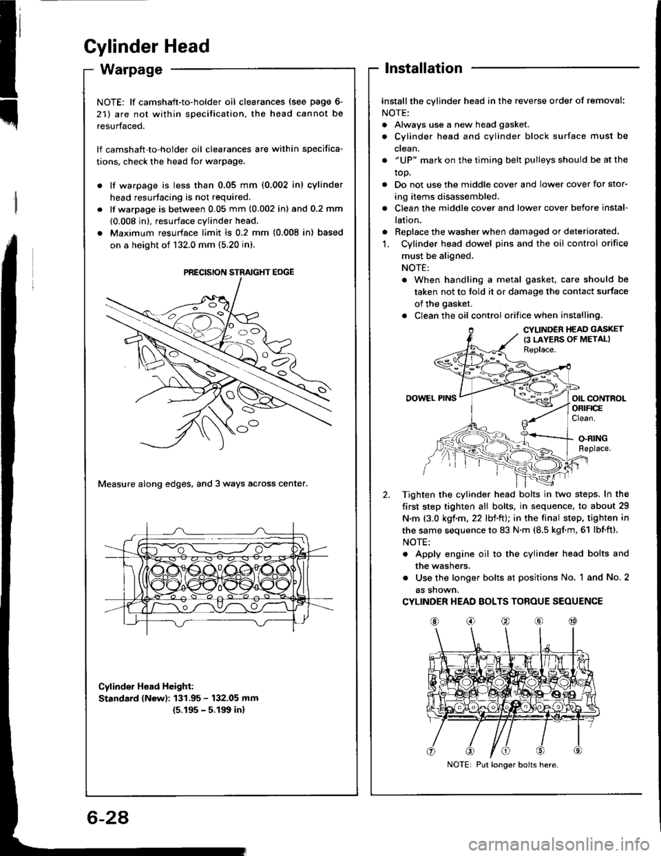
Gylinder Head
Installation
Installthe cylinder head in the reverse order of removal:
NOTE:
. Always use a new head gasket.
. Cylinder head and cylinder block surface must be
ctean.
. "UP" mark on the timing belt pulleys should be at the
top.
. Do not use the middle cover and lower cover for stor-
ing items disassembled.
. Clean the middle cover and lower cover before instal-
lation.
. Replace the washer when damaged or deteriorated.'1. Cylinder head dowel pins and the oil control orifice
must be aligned,
NOTE:
. When handling a metal gasket, care should be
taken not to told it or damage the contact surface
of the gasket.
. Clean the oil control orifice when installing.
CYLINDER HEAD GASKET
{3 LAYERS OF METALIReplace.
OOWEL PINSorl coNtnolORIFICEClean.
O.RINGReplace.
Tighten the cylinder head bolts in two steps. In the
Jirst step tighten all bolts, in sequence, to about 29
N.m {3.0 kgf.m, 22 lbl.ltJ; in the final step, tighten in
the same sequence to 83 N.m (8.5 kgf.m, 61 lbf'ft).
NOTE:
. Apply engine oil to the cylinder head bolts and
the washers.
. Use the longer bolts at positions No. 1 and No. 2
as shown.
CYLINDER HEAD BOLTS TOROUE SEOUENCE
@o@@@
NOTE: lf camshaft-to-holder oil clearances (see page 6-
21) are not within specitication, the head cannot be
resurfaced.
lf camshaft'to-holder oil clearances are within specifica-
tions, check the head for warpage.
lf warpage is less than 0.05 mm (0.002 in) cylinder
head resurtacing is not required.
lf warpage is between 0.05 mm (0.002 in) and 0.2 mm
(0.008 in), resurface cylinder head.
Maximum resurface limit is 0.2 mm (0.008 in) based
on a height of 132.0 mm (5.20 in).
Measure along edges, and 3 ways across center.
Cylinder Hoad Height:
Standard (New): 131.95 - 132.05 mm
{5.195 - 5.191t in}
PRECISION STRAIGHT EOGE
Put longer bolts here.
Page 133 of 1413
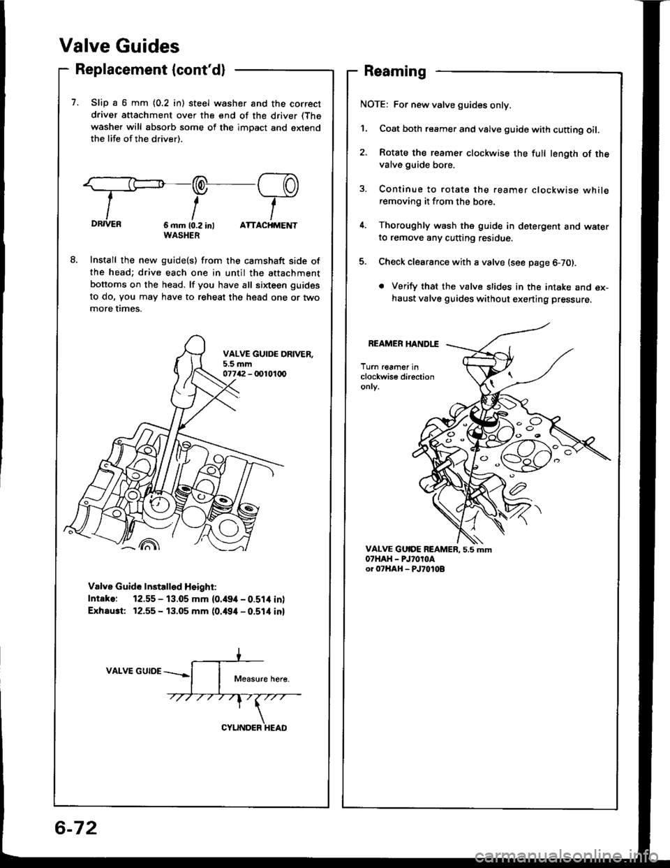
Valve Guides
Replacement (cont'dl
7. Slip a 6 mm {0.2 in) steel washer and the correct
driver attachment over the end of the driver (The
washer will absorb some of the imDact and extendthe life of the driver).
:=:-/--PDRIVER6 mm 10.2 int ATTACHMENTWASHER
Install the new guide(s) from the camshaft side ofthe head; drive each one in until the attachment
bottoms on the head. lf you have all sixteen guides
to do, Vou may have to reheat the head one or twomore times.
Valve Guide Installed Height:
Intake: 12.55 - 13.05 mm {0.49it - 0.51it inl
Exhaust 12.55 - 13.05 mm {0.494 - 0.514 inl
VALVE GUIDE
Reaming
NOTE: For new valve guides only.
1. Coat both reamer and valve guide with cutting oil.
2, Rotate the reamer clockwise the full length of thevalve guide bore.
3. Continue to rotate the reamer clockwise whileremoving it from the bore.
4. Thoroughly wash the guide in detergent and waterto remove any cutting residue.
5. Check clearance with a valve (see page 6-70).
. Verify that the valve slides in the intake and ex-haust valve guides without exerting pressure.
REAMER HANDLE
Turn reamer inclockwise directiononry.
C'
o
a
-'{)
6-72
Page 134 of 1413
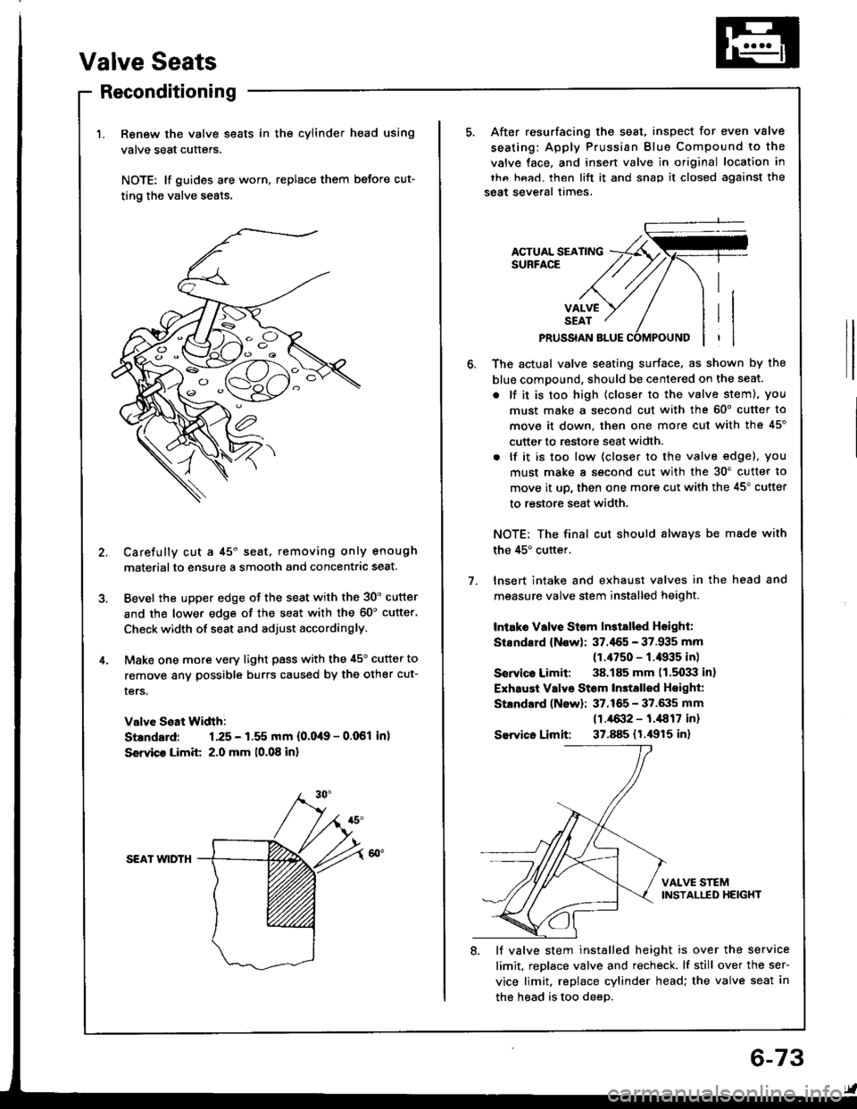
Valve Seats
Reconditioning
Renew the valve seats in the cylinder head using
valve seat cutters.
NOTE: lf guides are worn, replace them before cut-
ting the valve seats.
Carefully cut a 45o seat, removing only enough
materialto ensure a smooth and concentric seat.
Bevel the upper edge of the seat with the 30' cutter
and the lower edge of the seat with the 60'cutter'
Check width of seat and adjust accordingly.
Make one more very light pass with the 45o cutter to
remove anv possible burrs caused by the other cut-
ters.
Valve Seat Width:
Stlndard: 1.25 - 1.55 mm {0.0,19 - 0.061 in)
Ssrvico Limit 2.0 mm 10.08 in)
SEAI wlDTH
After resurfacing the seat, inspect for even valve
seating: Apply Prussian Blue Compound to the
valve face, and insen valve in original location in
thc hea.l. then lift it and snap it closed against the
seat several times.
ACTUAL SEATINGSURFACE
VALVESEAT
PRUSSIAN BLUE
1.
The actual valve seating surface, as shown by the
blue compound, should be centered on the seat.
. lf it is too high (closer to the valve steml, you
must make a second cut with the 60' cutter to
move it down, then one more cut with the 45'
cutter to restore seat width.
. lf it is too low (closer to the valve edge), you
must make a second cut with the 30'cutter to
move it up, then one more cut with the 45" cutter
to restore seat width.
NOTE; The final cut should alwavs be made with
the 45'cuttef.
lnsert intake and exhaust valves in the head and
measure valve stem installed height.
Intake Vllve St€m ln3tslled Hsighl:
Stsndard (Now): 37.'155 - 37.935 mm
(1.4750 - f .il935 in)
Sorvico Limit: 38.185 mm 11.5033 in)
Exhaust Valvo Stom In3talled Hoight:
Standard (Now): 37.165 - 37.6:15 mm
11.4{X}2 - 1.,1817 inr
Sewico Limit: 37.885 (1.i1915 in)
VALVE STEMINSTALLED HEIGHT
8. lJ valve stem installed height is over the service
limit, replace valve and recheck. lf still over the ser-
vice limit. replace cylinder head; the valve seat in
the head is too deeD.
6-73