check engine ACURA INTEGRA 1998 Service Owners Manual
[x] Cancel search | Manufacturer: ACURA, Model Year: 1998, Model line: INTEGRA, Model: ACURA INTEGRA 1998Pages: 1680, PDF Size: 53.14 MB
Page 360 of 1680
Clutch Pedal
Adjustment
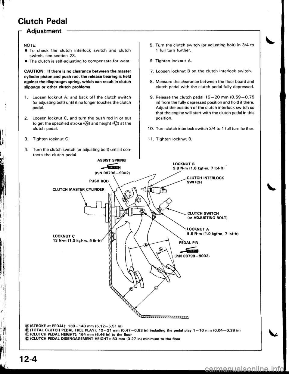
NOTE:
a To check the clutch interlock switch and clutch
switch, see section 23.
a The clutch is self-adjusting to compensate Ior wear.
CAUTION: ll there is no clealance between the master
cylinder piston and push rod, the release bearing is held
against the diaphragm spring, which can result in clutch
slippage or other clutch problems.
1. Loosen locknut A, and back off the clutch switch
(or adjusting bolt) until it no longer touches the clutch
peoal.
2. Loosen locknut C. and turn the push rod in or out
to get the specified stroke (@) and height {O) at the
clutch Dedal.
3. Tighten locknut C.
4. Turn the clutch switch (or adjusting bolt) until it con-
tacts the clutch pedal.
ASSIST SPRING
@{
{PiN 08798-9002t
(STROKE at PEDAL): 130-140 mm (5.12-5.51 in){TOTAL CLUTCH PEDAI- FREE PLAYI: 12-21 mm (0.47-0.83 inl including tho p6dal play{CLUTCH PEDAL HEIGHT): 164 mm 16.46 inl to the tloor(CLUTCH PEDAL DISENGAGEMENT HEIGHTI: 83 mm {3.27 inl minimum to the floo.
t?
5.Turn the clutch switch (or adjusring bolt) in 3/4 to
1 full turn further.
Tighten locknut A.
Loosen locknut B on the clutch interlock switch.
Measure the clearance between the floor board and
clutch pedal with the clutch pedal tully depressed.
Release the clutch pedal 15-20 mm (O.59-O.79
in) from the fully depressed position and hold it there.
Adjust the position of the clutch interlock switch so
that the engine will stan with the clutch pedal in this
position.
Turn clutch interlock switch 3/4 to 1 full turn further.
Tighten locknut B.
9.
6.
7.
8.
10.
11.
LOCKNUT B9.8 N.m 11.0 kgt.m, 7 lbl.ft)
CLUTCH INTERLOCKswrTcHPUSH ROD
CLUTCH MASTER CYLINDER
CLUTCH SWITCH(or AOJUSTING BOLT)
LOCKNUT A9.8 N.m (1.0 kgf.m, 7 lbt.frl
l
{P/N 0879a-9002)
12-4
1- 10 mm (0.O4-O.39 inl
Page 365 of 1680

Flywheel, Flywheel Bearing
Inspection
t
',4
i
Replacement
1. Install the special tool.
MOUNTING BOLTS
Remove the flywheel mounting bolts in a crisscrosspattern in several steps as shown, then.emove the
Jlvwheel.
Bemove the flywheel bearing from the flywheel.
(cont'd)
FLYWHEEL
I
1.Inspect the ring gear teeth tor wear and damage.
Inspect the clutch disc mating surtace on the
flywheel for wear, cracks, and burning.
l\,reasure the flywheel runout using a dial indicator
through at least two full turns. Push agsinst the
Jlywheel each time you turn it to take up the crank-
shatt thrust washer clearance.
NOTE: The runout can ba measured with engine in-
stalled.
SiEndrrd (Ncw): 0.05 mm (0.002 inl max.
SerYicc Llmh: 0.15 mm (0.006 inl
DIAL INOICATOR
lf the runout is more than the service limit, reolace
the flywheel.
Turn the inner race of the flywheel bearing with your
tinger. The bearing should turn smoothly and quiet-
ly. Check that the bearing outer race tits tightly in
the flvwheel.
FLYWHEELBEARING
lf the race does not turn smoothly, quietly, or tit
tight in the flywheel, replace the flywheel bearing.
4.
FLYWHEEL
12-9
Page 371 of 1680
aintenance
Transmission Oil
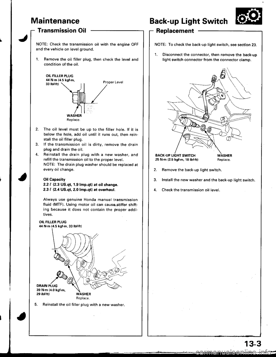
NOTE: Check the transmission oil with the engine OFF
and the vehicle on level ground.
1. Remove the oil filler plug, then check the level and
condition of the oil.
OIL FILLER PLUG44 N.m {4.5 kgf.m,Proper Level33 tbf.ftl
The oil level must be up to the filler hole. lf it is
below the hole, add oil until it runs out, then rein-
stall the oil filler plug.
lf the transmission oil is dirty, remove the drainplug and drain the oil.
Reinstall the drain plug with a new washer, and
refillthe transmission oilto the proper tevet.
NOTE: The drain plug washer should be replaced at
every oil change.
Oil Capacity
2.2 | i.2.3 US.qr,1.9 lmp.qtl at oil ch.nge.
2.3 t l2.1US.qt,2.O lmp.qtl at ovorhaul.
Always use genuine Honda manual transmission
fluid (MTF). Using motor oil can causa€tiffer shift-
ing because it does not contain the proper addi-
Back-up Light Switch
Replacement
NOTE: To check the back-up light switch. see section 23.
1. Disconnect the connector, then remove the back-up
light switch connector from the connector clamp.
l.m {2.5 kgf.m, 18lbf.ft) Replace.
Remove the back-up light switch.
Install the new washer and the back-up light switch.
Check the transmission oil level.
!ves.
OIL FILLER PLUG
DRAIN PLUG39 N.m {4.0 kg{.m,29 rbf.ftlReplace.
5. Reinstall the oil filler plug with a new washer,
Replace.
EACK.UP LIGHT SWITCH25 N.m {2.5 kgf.m, 18 lbf.ft)
13.3
Page 392 of 1680
Reassembly
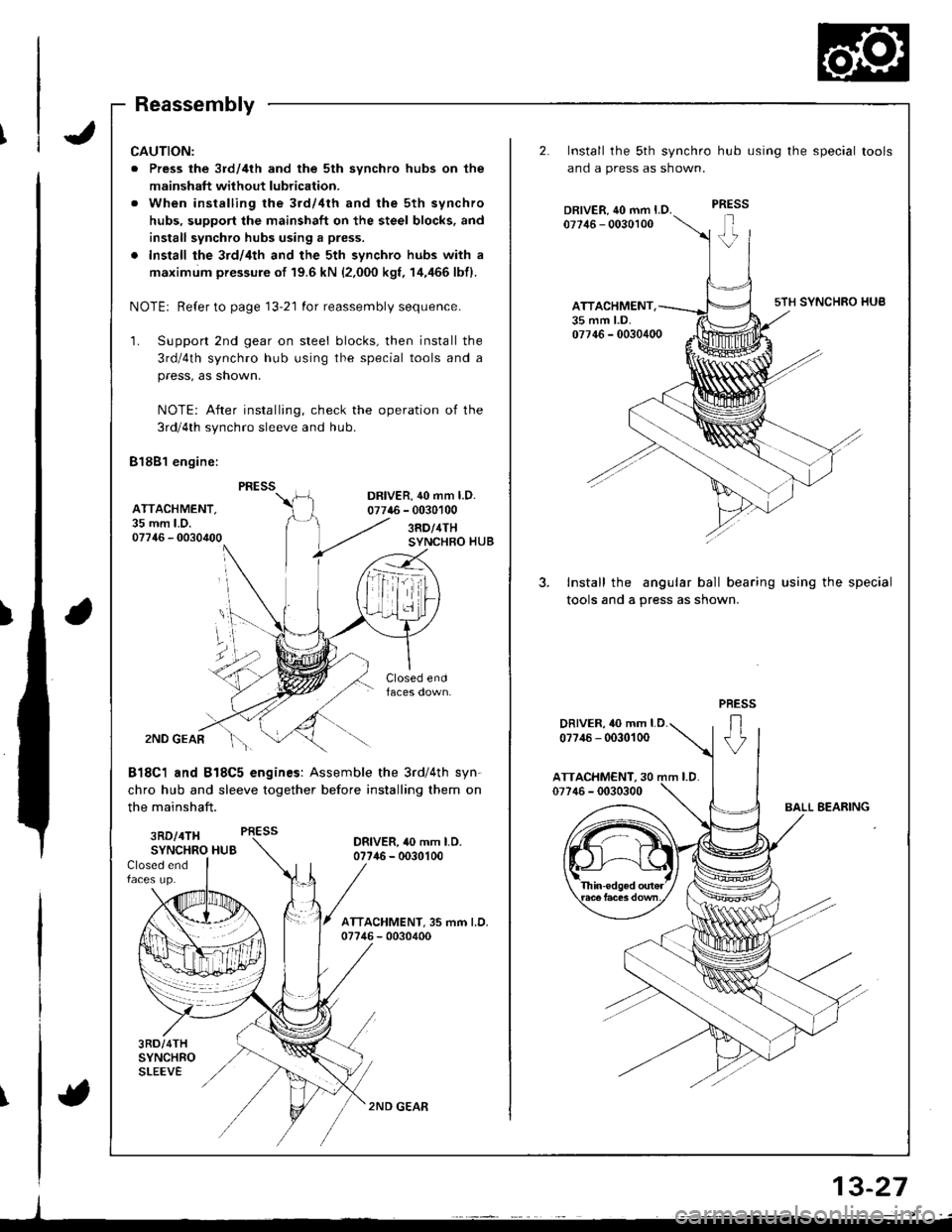
CAUTION:
. Press the 3rd/4th and the 5th synchro hubs on the
mainshaft without lubrication.
. When installing rhe 3rd/4th and the 5th synchro
hubs, support the mainshaft on the steel blocks. and
install synchro hubs using a press.
. Install the 3rd/4th and the 5th synchro hubs with a
maximum pressure of 19.6 kN {2,000 kgf, 14,/166 lbfl.
NOTE: Refer to page 13-21 for reassembly sequence.
'1. Support 2nd gear on steel blocks, then install the
3rd/4th synchro hub using the special tools and a
press, as shown.
NOTE: After installing, check the operation of the
3rd/4th synchro sleeve and hub
81881 engine:
DR|VER,40 mm l.D.07746 - 0030100AITACHMENT.35 mm LD.07746 - 00304003RD/4THSYNCHRO HUB
f
2ND GEAR
818C1 and B18C5 engines: Assemble the 3rd/4th syn-
chro hub and sleeve together before installing them on
the mainshaft.
3RD/4TH PRESS
SYNCHRO HUBORIVER, 40 mm LO.07746 - 0030100Closed endfaces up.
3RD/4THSYNCHROSLEEVE
2ND GEAR
2.
3.
Install the sth synchro hub using the special tools
ano a press as snown.
Install the angular ball bearing using the special
tools and a press as shown.
ATTACHMENT.35 mm LD.
DRIVER, 10 mm LD.
07?,16 - 0030100
J
a
\
13-27
{
Page 411 of 1680
I
Transmission Assembly
1.
2.
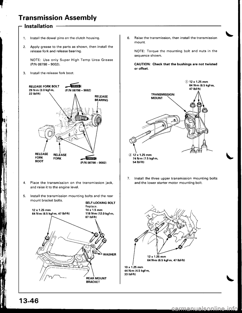
Install the dowel pins on the clutch housing.
Apply grease to the parts as shown, then install the
release fork and release bearing.
NOTE: Use only Super High Temp Urea Grease
(P/N 08798 - 9002).
3. Install the release fork boot.
lnstallation
22 tbl.lll
RELEASE FORK BOLT29 N.m {3.0 kgl.m,{P/N 08798 - 9002t
RELEASEBEAFING
RELEASEFORK
lPlN 08798 - 90021
Place the transmission on the transmission jack,
and raise it to the engine level.
Install the transmission mounting bolts and the rear
mount bracket bolts.SELF.LOCKING BOLT
12 x 1.25 mm64 N.m {6.5 kgf.m, {7 lbtftl
Replace.14 x 1.5 mm
RELEASEFORKBOOT
\i'l-r )i-
.+.i
13-46
6. Raise the transmission, then install the transmission
mounr,
NOTE: Torque the mounting bolt and nuts in the
sequence shown.
CAUTION: Check that the bushings are not twisted
or offset.
!) tz x t.zs mm64 N.m {6.5 kgt.m,47 tbl.ftl
7. Install the three upper transmission mounting
and the lower staner motor mountinq bolt.
bolts
10 x 1.25 mm44 N.m (4.5 kgt m.33 tblftl
(a 12 x 1.25 mm74 N.m {7.5 kgf m,54 tbf.ft)
'12x1.25m�n
64 N.m {6.5 kst.m,47 lbf,ft)
Page 419 of 1680
Description
\J
t{
{
14-3
The automatic transmission is a combination of a 3-element torque converter and triple-shalt electronically controlled
automatic transmission which provides 4 speeds forward and 1 speed reverse. The entire unit is positioned in line with
the engrne.
Torque Converter, Gears, and Clutches
The torque converter consists of a pump, turbine, and stator, assembled in sigle unit. The torque converter is connected to
the engine crankshaft so they turn torether as a unit as the engine turns. Around the outside of the torque convener is a
ring gear which meshes with the starter pinion when the engine is being started. The entire torque converter assembly
serves as a flywheel while transmitting power to the transmission mainshaft.
The transmission has three parallel shafts; the mainshaft. the countershaft, and the sub shaft. The mainshaft is in-line with
the engine crankshaft.
The mainshaft includes the 1st, and 2ndl4th clutches,and gear for 3rd, 2nd, 4th, reverse, and 1st. (3rd gear is integral with
the mainshaft, while reverse gear is integral with the 4th gear.)
The countershaft includes the 3rd clutch and gears for 3rd,2nd, 4th, reverse, 1st, and parking. Reverse and 4th gears can
be loched to the countershaft at its center,providing 4th gear or reverse, depending on which way the selector is moved.
The sub-shaft includes the 1st-hold clutch and gears fo 1st and 4th.
The gears on the mainshaft are in constant mesh with those on the countersahft and sub-shaft.When certain combinations
of gears in the transmission are engaged by clutches. power in transmitted from the mainshaft to the countershaft via the
sub-shaft to orovude oil, lo'1. E, E. and E.
Electronic Control
The electronic control svstem consists of the Transmission Control Module (TCM), sensors, and four solenoid valves.
Shilting and lock-up are electronically controlled for comfortable driving under all conditions.
The TCM is located below the dashboard, behind the lelt side kick panel on the driver's side.
Hydraulic Control
The valve bodies include the main valve body, the secondary valve body, the regulator valve body, the serbvo body, and
the lock-up valve body, through the respective separator plates, They are bolted to the torque converter housing,
The main valve body contains the manual valve, the 1-2 shift valve, the 2-3 shitt valve, the Clutch Pressure Control
lCPC) valve, the 4th exhaust valve, the reliel valve, and the ATF pump gears.
The secondary valve body contains the 4-3 kick-down valve, the 3-2 kick-down valve, the 2-3 orifice control valve, the
3-4 shift valve, the orilice control valve, the modulator valve, and the servo control valve.
The regulator valve body contains the pressure regulator valve, the lock-up control valve, the torque converter check
valve, and the cooler check valve.
The servo body contains the servo valve, which is integrated with shift fork shaft, the throttle valve B, and the accumula-
tors.
The lock-up valve body contains the lock-up shift valve and the lock-up timing B valve, and is bolted to the regulator valve
ooqy.
Fluid from the regulator passes through the manual valve to the various control valves.
Shift Control Mechanism
Input to the TCM from various sensors located throughout the car determines which shift control solenoid valve should
be activated. Activating a shitt control solenoid valve changes modulator pressure, causing a shift valve to move. This
pressurizes a line to one ol the clutches, engaging that clutch and its corresponding gear.
Lock-uD Mechanism
In @ position, in 2nd, 3rd and 4th, and @ position in 3rd, pressurized fluid can be drained lrom the back oI the tor-
que converter through a fluid passage, causing the lock-up piston to be held against the torque converter cover. As this
takes place, the mainshaft rotates at the same speed as the engine crankshaft. Together with hydraulic control, the TCM
optimizes the timing of the lock-up mechanism.
The lock-up valves controlthe range of lock-up according to lock-up control solenoid valves A and B, and throttle valve B.
When lock-up control solenoid valves A and B activate, modulator pressure changes. Lock-up control solenoid valves
A and B are mounted on the torque converter housing, and are controlled by the TCM.
(cont'd)
Page 445 of 1680
I
I
I
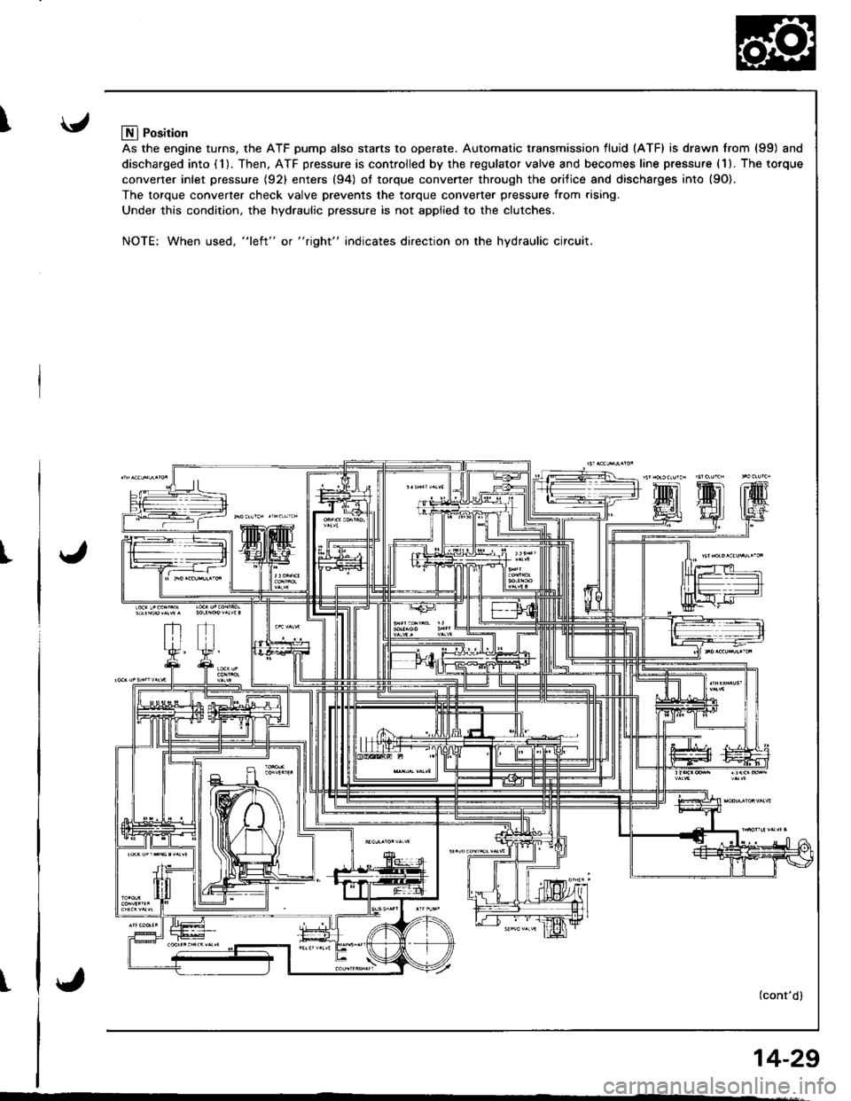
Llfl Position
As the engine turns, the ATF pump also starts to operate. Automatic transmission fluid (ATF) is drawn from (99) and
discharged into (1). Then, ATF pressure is controlled by the regulator valve and becomes line pressure (1). The torque
converter inlet pressure {92} enters (94) ol torque converter through the orilice and discharges into {9O).
The torque converter check valve prevents the torque converter pressure from rising.
Under this condition, the hydraulic pressure is not applied to the clutches.
NOTE: When used, "l€ft" or "right" indicates direction on the hydraulic circuit.
(cont'dl
14-29
Page 465 of 1680
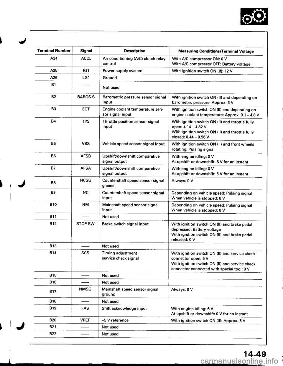
Terminal NumberSignalDescriptionMaasuring Conditlons/Tarminal Voliage
424ACCLAir conditioning (Ay'C) clutch relay
control
With A,/C comDressor ON: 0 V
With Ay'C compressor OFF: Battery voltage
A25tG1Power supply systemWith ignition switch ON (ll)r 12 V
426LG1Ground
B1Not used
82BAROS SBarometric pressure sensor signal
input
With ignition switch ON (ll) and depending on
barometric pressure: Approx. 3 V
B3ECTEngine coolant temperature sen-
sor signal input
With ignition switch ON (ll) and depending on
engine coolant tem perature: Approx. 0.1 - 4.8 V
B4TPSThrottle position sensor signal
input
With ignition switch ON (ll) 8nd throttle fully
open: 4.14 - 4.82 V
With ignition switch ON (ll) and throttle fully
closed: 0.44 - 0.56 V
B5VSSVehicle speed sensor signal inputWith ignition switch ON (ll) and front wheels
rotating; Pulsing signal
B6AFSBUpshifvdownshift comparative
signal output
With engine idling: 0 V
At uDshift or downshift: 5 V for an instant
B7AFSAUpshifvdownshift com parative
srgnal output
With engine idling: 0 V
At upshift or downshift: 5 V for an instant
B8NCSGCountershaft speed sensor signal
ground
Always: 0 V
B9NCCountershaft speed sensor signal
Input
Depending on vehicle speed: Pulsing signal
When vehicle is stopped:0 V
B10NMMainshaft speed sensor signal
input
Depending on vehicle speed: Pulsing signal
When vehicle is stoDoed: 0 V
811Not used
812STOP SWBrake switch signal inputWith ignition switch ON {ll) and b.ake pedal
depressed: Battery voltage
With ignition switch ON (lll and brake pedal
released:0 V
813Not used
814scsTiming adjustment
service check signal
With ignition switch ON (ll) and service check
connector oDen:5 V
With ignition switch ON (ll) and service check
connector connected with special tool: 0 V
815Not used
816Not used
817NMSGMainshaft speed sensor signalgroundAlways: 0 V
818Not used
819FASShift acknowledge inputWith engine idling: 5 V
At upshift or downshift: 0 V for an instant
820VBEF+5 V referenceWith ignition switch ON {lll: Approx. 5 V
82'lNot used
Not used
14-49
Page 470 of 1680

Diagnostic
Trouble Code(Drc)*
,94
lndicator
Light
SymptomPossible CauseRefer to
Page
P1153(1)Blin ks
Lock-up clutch does not engage,
Lock-up clutch does not disen-
gage.
Disconnected lock-up control solenoid
valve A connector
Short or open in lock-uP control
solenoid valve A wire
Faulty lock-up control solenoid valve A
14-56
P1758
t2lBlinks
. Lock-up clutch does not engage.Disconnected lock-up control solenoid
valve B connector
Short or open in lock-uP control
solenoid valve B wire
Faulty lock-up control solenoid valve B
14-58
P1790(3)Blinks
. Lock-up clutch does not engage.Disconnected throttle position (TP)
sensor connector
Short or open in TP seflsor wire
Faulty TP sensor
14-60
P1191(4)Blinks
. Lock-up clutch does not engage.Disconnected vehicle speed sensor
{VSS} connector
Shon or open in VSS wire
Faulty VSS
14-61
P1705
(5)Blinks
. Fails to shift other than 2nd - 4th
gears.
. Lock-up clutch does not engage.
. Shod in AvT gear position switch wire
. Faulty A,/T gear position switch14-62
P1706(6)OFF
' Fails to shift other than 2nd -
3rd - 4th gears.
. Lock-up clutch does not engage.
Disconnected A/T gear position switch
connector
Open in A/f gear position switch wire
Faulty A/f gear position switch
14-64
P0753
(71Blinks
. Fails to shift (between 1st - 4th
or 2nd - 3rd gear only).. Fails to shift (stuck in 4th gear).
Disconnected shift control solenoid
valve A connector
Short or open in shift control solenoid
valve A wire
Faulty shift control solenoid valve A
14-66
P0758(8)Blinks
. Fails to shift (stuck in 1st or 4th
gears).
Disconnected shift control solenoid
valve B connector
Short or open in shift control solenoid
valve B wire
Faulty shift control solenoid valve B
14-68
P0120(9)Blin ks
Lock-up clutch does not engage.Disconnected countershaft speed sen-
sor connector
Short or open in countershaft speed
sensor wrre
Faulty countershaft speed sensor
1+10
P1192
00)Blinks
. Lock-up clutch does not engage,Disconnected engine coolant tempera-
ture (ECT) sensor connector
Short or open in ECT sensor wire
Faulty ECT sensor
14-72
P0725
{1 1)OFF
Lock-up clutch does not engage.Disconnected ignition coil connector
Short or open in ignition coil wire
Faulty ignition coil
14-73
Symptom-to-ComPonent Chart
Electrical System
(DTC)*: The DTCS in the parentheses are the codes the E indicator light indicates {blinks) when the service check connec-
tor is connected to the special tool (SCS service connector)
4-54
Page 488 of 1680
Electrical Troubleshooting
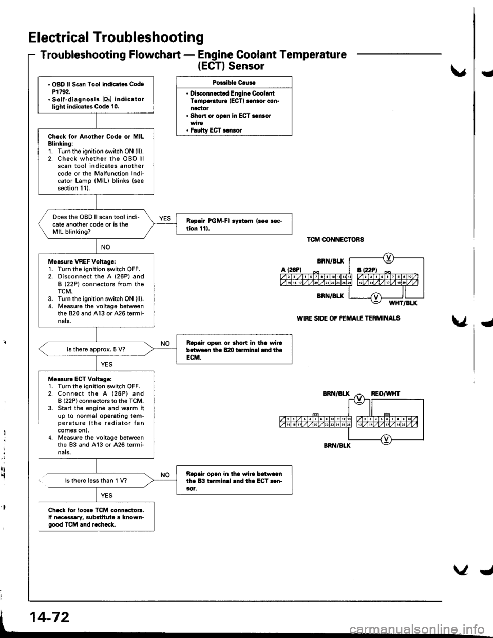
Troubleshooting Flowchart - Engine Coolant Temperature
(EGTISensor
Polribl. Cluta
. Dirconnoct.d Engin. CoollntTampaolur€ IECTI aanaor con.noctot. Short or opcn In ECT..n.or
. F.ulty ECT r.n.or
Tctrrt oot{NEcToRs
WIRE SIDE OF FEMAII TERi'IINAIS
U
{
M6esur. ECT Voh.ge:1. Turn the ignition switch OFF.2. Connect the A (26P) andB (22P) connectors to the TCM.3. Start the engine and w6rm ituP to normal operating tem-pe ratu re (the radiator fancomes on),4, Measure the voltage betweenthe 83 and A13 or A26 termi-nats.
Ii
:
rt.fls there less than 1 V?
Ch.cl fo. looso TCM connac{or3,t nacaasary, substituto a known"good TCM rnd r.chock.
' OBD ll Scsn Tool Indicat6 CodeP1792.. Sett'diagno3i3 E indicatollight indicates Code 10.
Chock tor Anothor Codo or MILBlinking:1. Turn the ignition switch ON (ll).
2. Check wh€ther rhe OBD llscan tool indicates anothercode or the Malfunction Indi-cator Lamp (MlL) blinks (see
section 11).
Does the OBD ll scan tool indi-cate another code or is theMIL blinking?
Moasure VREF Voh.go:1. Turn the ignition switch OFF.2. Disconnect the A {26P) andB (22P) conneotors from theTCM.3. Turn the ignition switch ON (ll).
4. Measu.e the voltage betweenthe 820 and A13 or A26 tormi-nals.
Bap|ir open or thort in tha wircb.two.r th. B:m t.rminll .nd thoECM.
ls there approx. 5 V?
napalr opln in iha wlra brtwaanthe lB t.rminrl lnd th. ECT r.n-ao1.