ACURA INTEGRA 1998 Service Repair Manual
Manufacturer: ACURA, Model Year: 1998, Model line: INTEGRA, Model: ACURA INTEGRA 1998Pages: 1680, PDF Size: 53.14 MB
Page 1011 of 1680
Heater Control Panel
Replacement
J
2.
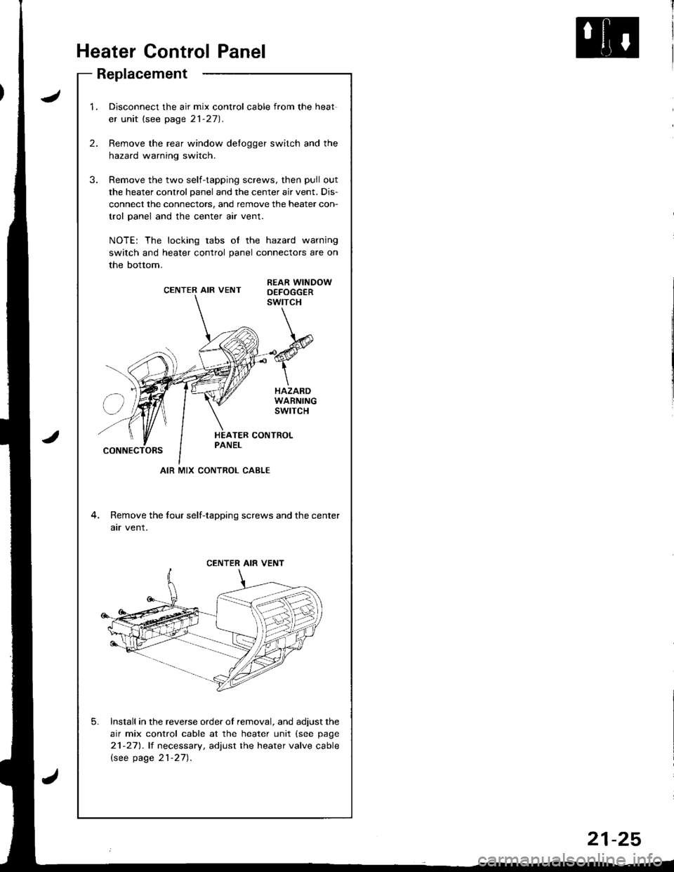
1.Disconnect the air mix control cable from the heat
er unit (see page 21-27).
Remove the rear window delogger switch and the
hazard warning switch.
Remove the two self-tapping screws, then pull out
the heater control panel and the center air vent. Dis-
connect the connectors, and remove the heater con-
trol panel and the center air vent.
NOTE: The locking tabs of the hazard warning
switch and heater control panel connectors are on
the bottom.
CENTER AIR VENTREAR WINDOWD€FOGGERswtrcH
HAZARDWARNINGswrTcH
CONNECTORS
4. Remove the four self-tapping screws and the center
atr vent.
Install in the reverse order of removal, and adjust the
air mix control cable at the heater unit (see page
21-271.lt necessary, adjust the heater valve cable
lsee page 21-27).
5.
AIR MIX CONTROL CABLE
CENTER AIR VENT
21-25
Page 1012 of 1680
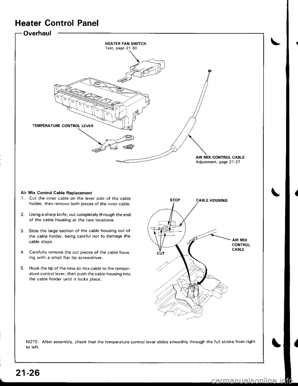
HEATER FAN SWITCHTest, page 21 30
AIR MIX CONTROL CABLEAdjustment, page 21-27
Air Mix Contlol Cable ReDlacement
1. Cut the inner cable on the lever side of the cable
holder, then remove both pieces of the inner cable.
2.Using a shafp knife, cut completely through the end
of the cable housing at the two locations.
Slide the large section of the cable housing out of
the cable holder, being careful not to damage the
cable stops.
Carefully remove the cut pieces of the cable hous
ing with a small tlat tip screwdriver.
Hook the tip of the new air mix cable to the temper-
ature control lever, then push the cable housing into
the cable holder until it locks place.
3.
AIR MIXCONTROLCABLE
5.
NOTEr Atter assembly, check that the temperature control lever slides smoothly through the full stroke from right
to left.
Heater Control Panel
Overhaul
t
21-26
Page 1013 of 1680
Heater Valve Cable
Adjustment
Air Mix Control Cable
Adjustment
lnri
I
I
I
I
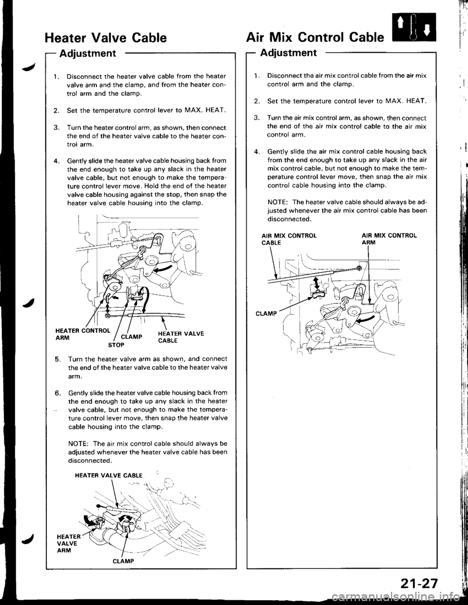
l.Disconnect the heater valve cable from the heater
valve arm and the clamp, and from the heater con-
trol arm and the clamp.
Set the temperature control lever to MAX. HEAT.
Turn the heater control arm, as shown, then connect
the end of the heater valve cable to the heater con-
trol arm.
Gently slide the heater valve cable housing back from
the end enough to take up any slack in the heater
valve cable, but not enough to make the tempera-
ture control lever move. Hold the end of the heater
valve cable housing against the stop, then snap the
heater valve cable housing into the clamp.
HEATER CONTROLARM
HEATERVALVEARM
HEATER VALVECABLECLAMP
5. Turn th€ heater valve arm as shown, and connect
the end of the heater valve cable to the heater valve
arm.
STOP
6. Gently slide the heater valve cable housing back from
the end enough to take up any slack in the heater
valve cable, but not enough to make the tempera-
ture control lever move. then snap the heater valve
cable housing into the clamp.
NOTE: The air mix control cable should alwavs be
adjusted whenever the heater valve cable has been
disconnected.
HEATER VALVE CABLE
,i$.
CLAMP
1.Disconnect the air mix control cable from the air mix
control arm and the clamp.
Set the temperature control lever to MAX. HEAT.
Turn the air mix controlarm, as shown, then connect
the end of the air mix control cable to the air mix
control arm.
Gently slide the air mix control cable housing back
from the end enough to take up any slack in the air
mix control cable, but not enough to make the tem-
perature control lever move, then snap the air mix
control cable housing into the clamp.
NOTE: The heater valve cable should always be ad-
justed whenever the air mix control cable has been
disconnected.
2.
3.
AIR MIX CONTROLCABLEAIR MIX CONTROLARM
21-27
Page 1014 of 1680
Mode Control Motor
Test
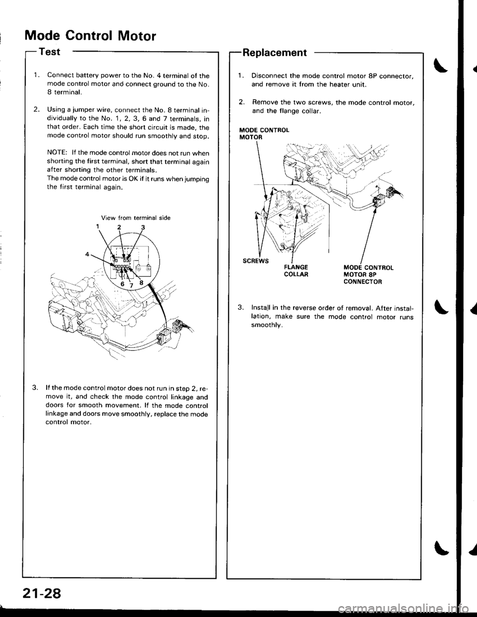
Connect battery power to the No. 4 terminal of themode control motor and connect ground to the No.
I terminal.
Using a jumper wire, connect the No. 8 termjnal in-dividually to the No. 1, 2, 3, 6 and 7 terminals, inthat order. Each time the short circuit is made. themode control motor should run smoothly and stop.
NOTE: lf the mode control motor does not run whenshorting the first terminal, short that te.minal againafter shorting the other terminals.
The mode control motor is OK if it runs when jumping
the tirst terminal again.
lf the mode control motor does nol run in steD 2, re-move it, and check the mode control linkage anddoors for smooth movement. lf the mode controllinkage and doors move smoothly, replace the mode
control motor.
Replacement
MODE CONTROLMOTOR
Disconnect the mode control motor 8P connector,
and remove it lrom the heater unit,
Remove the lwo sc.ews, the mode control motor,
and the flange collar.
MODE CONTROLMOTOR 8PCONNECTOR
Install in the reverse order of removal. After instal-lation, make sure the mode control motor runssmoothly.
21-28
Page 1015 of 1680
lli
''
ltRecirculation Control Motor
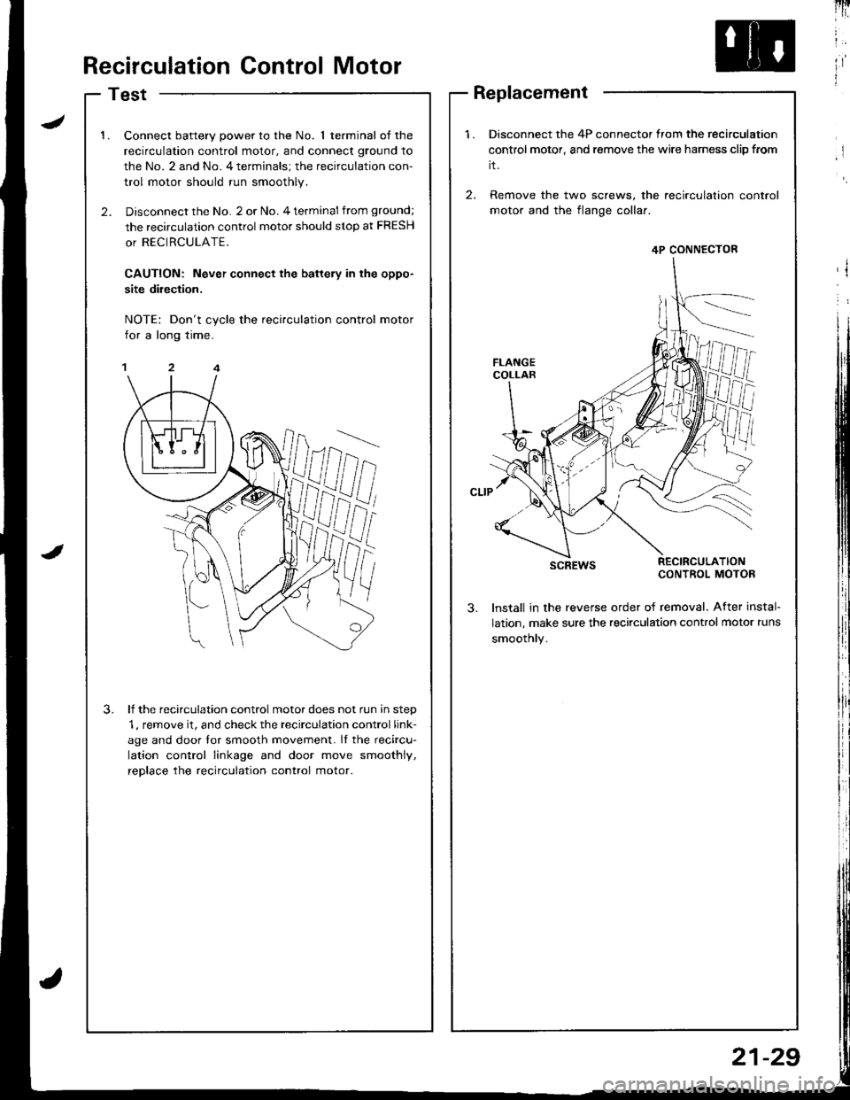
Test
1.Connect battery power to the No. 1 terminal of the
recirculation control motor, and connect ground to
the No. 2 and No. 4 terminals; the recirculation con-
trol motor should run smoothly.
Disconnect the No. 2 or No. 4 terminal from ground;
the recirculation control motor should stop at FRESH
or RECIRCULATE.
CAUTION: Never connect the battery in the oppo-
site dilection.
NOTE: Don't cycle the recirculation control motor
for a long time.
lf the recirculation control motor does not run in step
1, remove it, and check the recirculation control link-
age and door lor smooth movement. If the recircu-
lation control linkage and door move smoothly,
reDlace the recirculation control motor.
3.
1.Disconnect the 4P connector from the recirculation
control motor, and remove the wire harness clip from
it.
2. Remove the two screws, the recirculation
motor and the flange collaf.
scREwsRECIRCULATIONCONTROL MOTOB
lnstall in the revefse order of removal. After instal-
lation, make sure the recirculation control motor runs
smoothly.
4P CONNECTOR
Replacement
21-29
Page 1016 of 1680
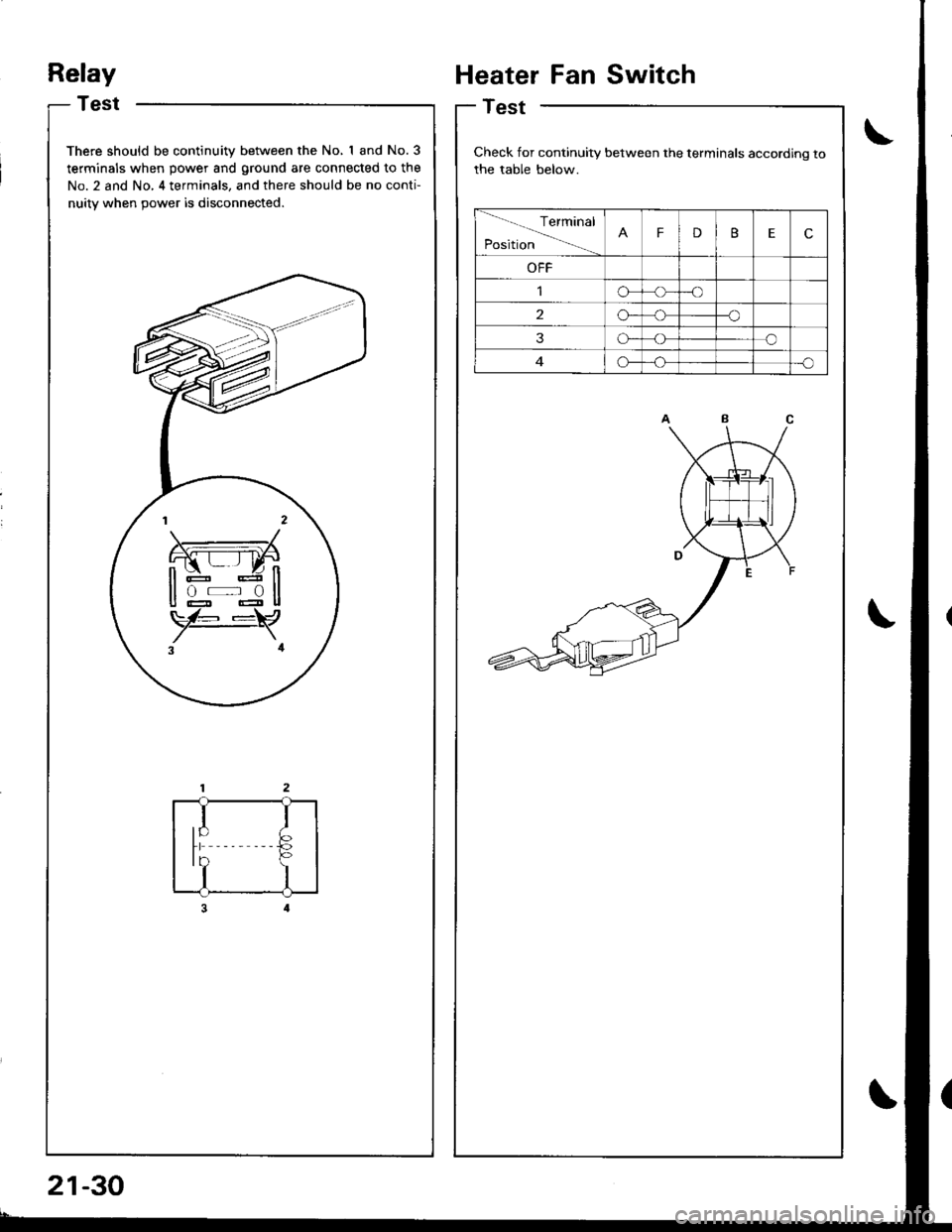
Relay
Test
There should be continuity between the No, I and No.3
terminals when power and ground are connected to the
No. 2 and No, 4 terminals, and there should be no conti-
nuitv when 9ower is disconnected.
rl
I
tb
I
Heater Fan Switch
Test
Check for continuity between the terminals according to
the table below.
Terminal
PositionFDBEc
OFF
o-o
2o--o
3o-o
G_o
21-30
Page 1017 of 1680
![ACURA INTEGRA 1998 Service Repair Manual
Mode Control Switch
Test
!;:l#,",ion
contro,
m
lTit
l,
t
,l
Switch
Test
Check for continuity between the terminals according to
the table below.
Terminal
Position56
Fresho1]
Recirculateo--o
Check ACURA INTEGRA 1998 Service Repair Manual
Mode Control Switch
Test
!;:l#,",ion
contro,
m
lTit
l,
t
,l
Switch
Test
Check for continuity between the terminals according to
the table below.
Terminal
Position56
Fresho1]
Recirculateo--o
Check](/img/32/56983/w960_56983-1016.png)
Mode Control Switch
Test
!;:l'#,",ion
contro,
m
lTit
l,
t'
,l
Switch
Test
Check for continuity between the terminals according to
the table below.
Terminal
Position56
Fresho1]
Recirculateo--o
Check for continuity between the termsssssafrinals according to
the table below.
Terminal
Position1237I
HeatG{
Heat/Defo-!
DefG-o
Go
Heat/Vent>'--o
Page 1018 of 1680
Air Gonditioning
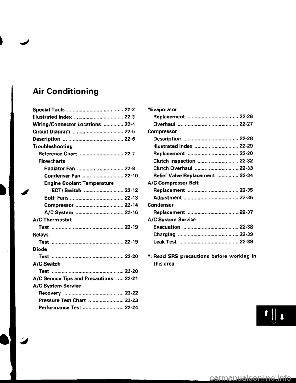
+Evaporator
Repf acement .........22-26
Overhauf ................22-27
Compressor
Description ............22-28
lf lustrated f ndex ............................... 22-29
Replacement .........22-30
Cf utch Inspection ....................... ...... 22-32
Cf utch Overhau1 ........................ ....... 22-33
Ref ief Vaf ve Replacement ............... 22-34
A/C Compressor Belt
Repf acement .........22-35
Adiustment ............22-36
Condenser
Repf acement .........22-37
A/C System Service
Evacuation .............22-38
Charging ................22-39
Leak Test ...............22-39
*: Read SRS precautions before working in
this area.
Page 1019 of 1680
Special Tools
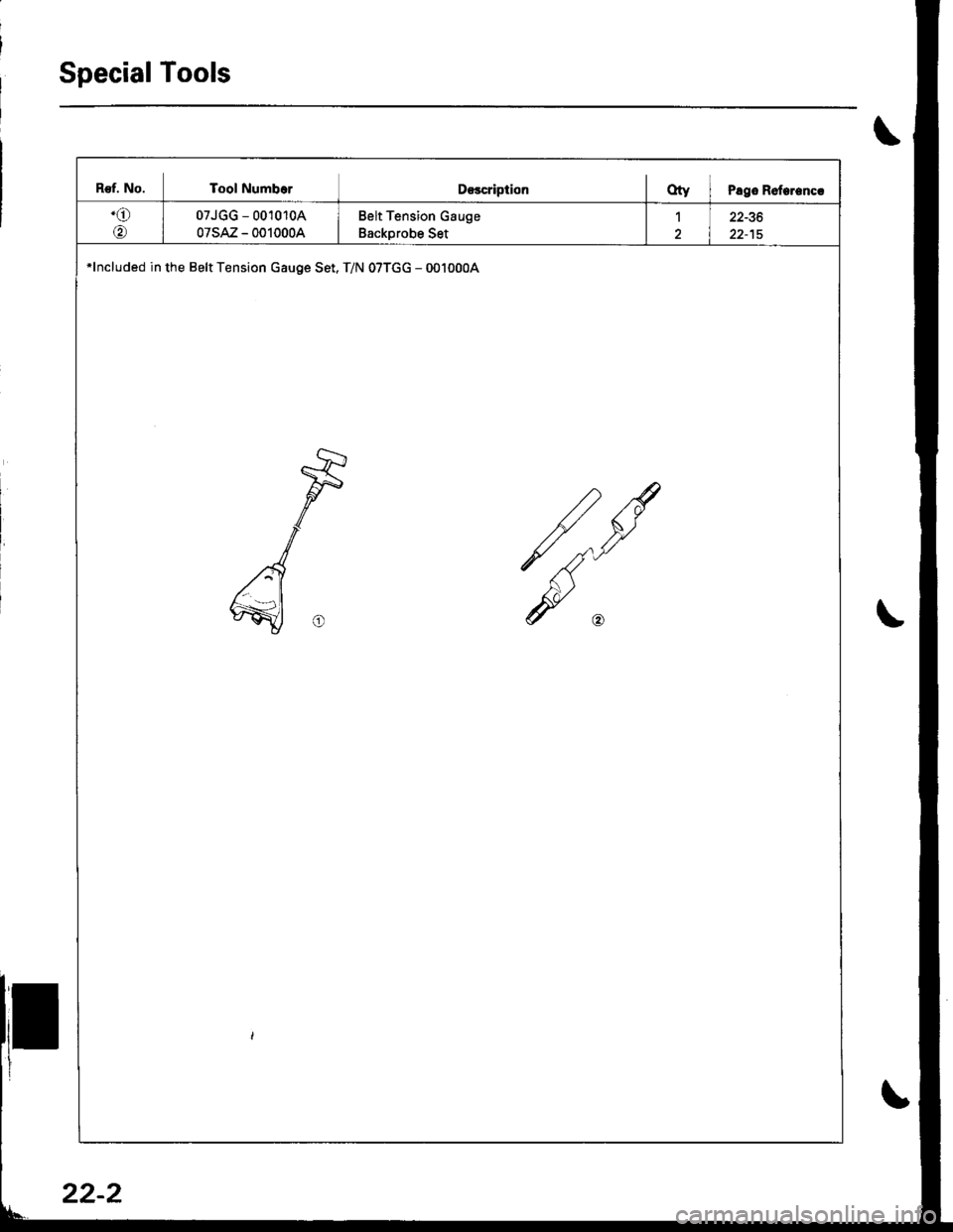
B€f. No. Tool NumborD€scriptionOty I Pago Roterencr
.o
@
07JGG - 001010A
07sAz - 0010004
Belt Tension Gauge
Backprobe Set
122-36
*lncluded in the Belt Tension Gauge Set. T/N 07TGG - 0010004
22-2
Page 1020 of 1680
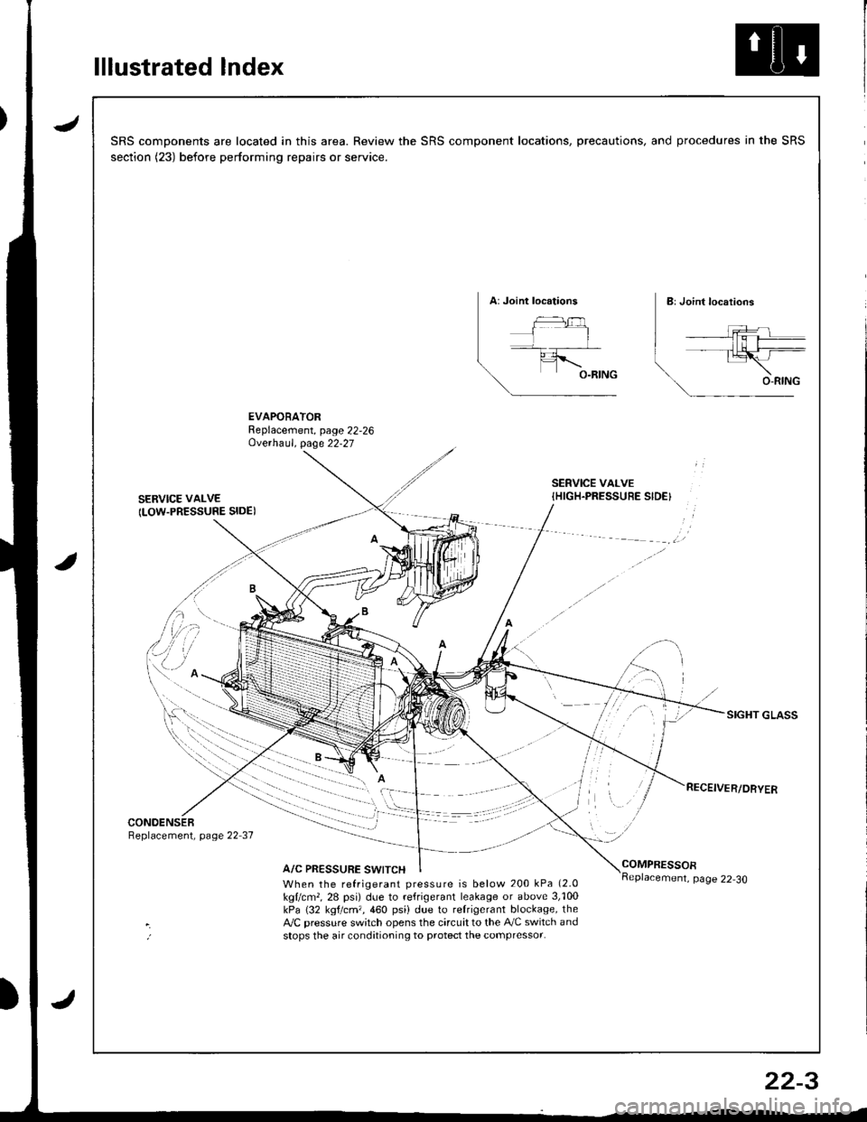
lllustrated Index
JSRS components are located in this area. Review the SRS component locations, precautions, and procedures in the SRS
section (23) before performing repairs or service.
EVAPORATORReplacement, page 22,26Ove.haul. page 22-27
SERVICE VAI-VE
ILOW.PRESSURE SIDE)
SERVICE VALVE{HIGH.PRESSUEE SIDE}
SIGHT GLASS
CONOENSERReplacement, page 22 37
A/C PRESSURE SWITCHCOMPRESSOR
When the refrigerant pressure is below 200 kPa (2.0
kgllcm,, 28 psi) due to refrigerant leakage or above 3,'100kPa (32 kgtcm,,460 psi) due to relrigerant blockage, theA,/C pressure sw;tch opens the circuit to the A,/C switch andstops the air conditioning to protect the compressor.
page 22-30
22-3