ACURA INTEGRA 1998 Service Repair Manual
INTEGRA 1998
ACURA
ACURA
https://www.carmanualsonline.info/img/32/56983/w960_56983-0.png
ACURA INTEGRA 1998 Service Repair Manual
Trending: fuse, oil temperature, CD player, remove seats, engine oil capacity, USB, coolant temperature
Page 1061 of 1680
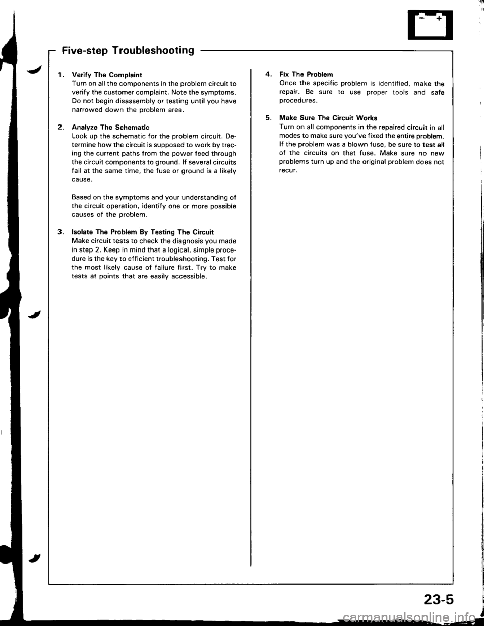
I . Verify The Complaint
Turn on allthe components in the problem circuit to
verify the customer complaint. Note the symptoms.
Do not begin disassembly or testing until you have
narrowed down the problem area.
2- Analyze The Schomatic
Look up the schematic for the problem circuit. De-
termine how the circuit is supposed to work by trac-
ing the current paths from the power feed through
the circuit components to ground. lf several circuits
fail at the same time, the fuse or ground is a likely
Based on the symptoms and your understanding ot
the circuit operation, identity one or more possible
causes of the problem.
3. lsolata The Problem By Testing The Circuit
Make circuit tests to check the diagnosis you made
in step 2. Keep in mind that a logical, simple proce-
dure is the key to efficient troubleshooting. Test for
the most likely cause of failure lirst. Try to make
tests at points that are easilV accessible.
4. Fix The Problem
Once the specific problem is identified, make therepair. Be sure to use proper tools and safep.ocedures.
5. Make Sure The Circuit Workg
Turn on all components in the repaired circuit in allmodes to make sure you've fixed the entire problem.
lf the problem was a blown fuse, be sure to test all
of the circuits on that fuse. Make sure no newproblems turn up and the original problem does not
recuf.
Page 1062 of 1680
Troubleshooting
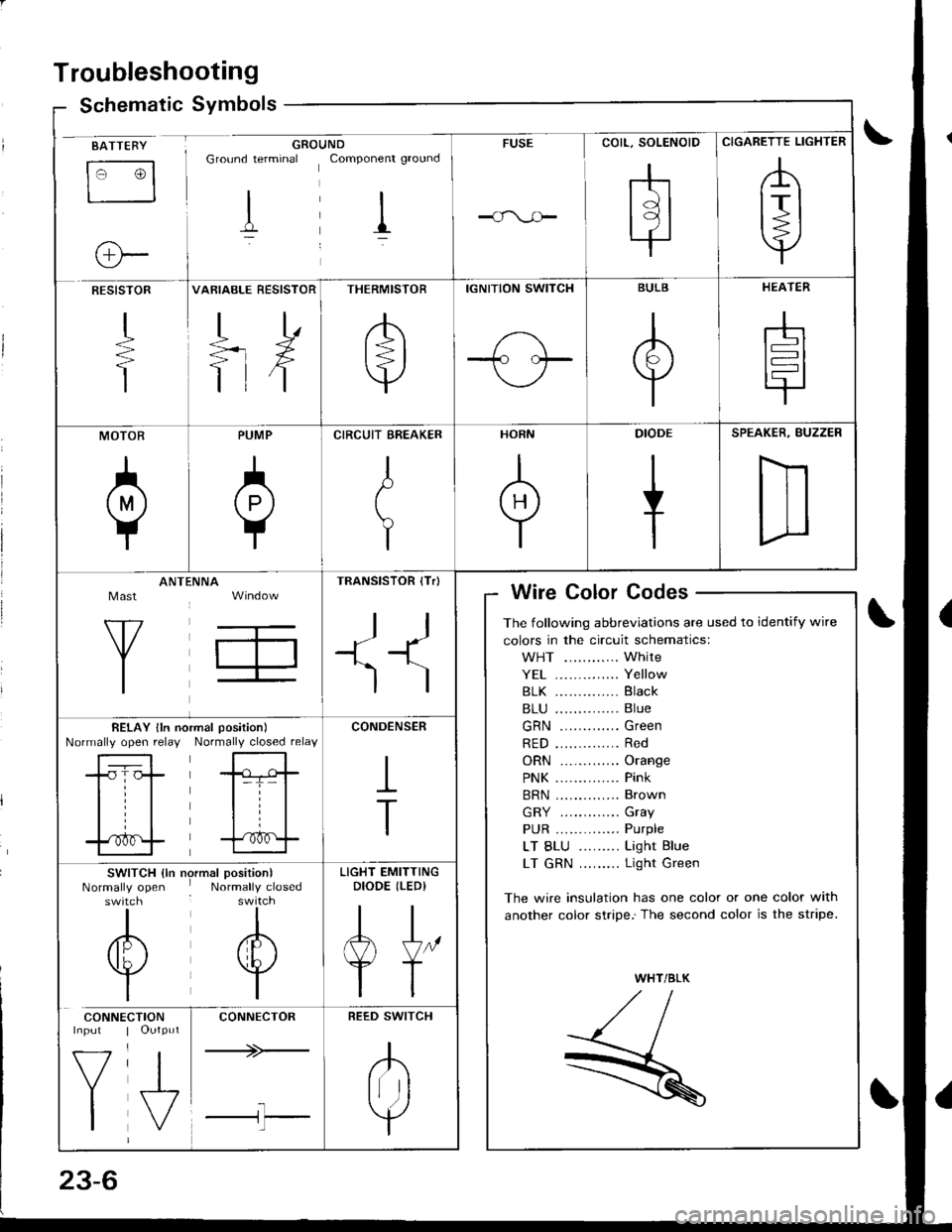
Schematic Symbolsym
BATTEBY
tr3
o-
GROUNDGround terminal Componenr ground
I il
FUSE
COIL, SOLENOID
rhtdl
l9l.|
CIGARETTE LIGHTER
,A
lrl
Y
RESISTOR
+
T
VARIABLE RESISTOR
TD
=rX
ttf
THERMISTOR
/b'
t=l
v
IGNITION SWITCH
1-\-T- l.--
BULB
A
Y
HEATER
-h
t=l
tr
MOTOR
0
PUMP
A
Y
CIRCUIT EREAKER
I
t
Y
HORN
+
DIODE
+
SPEAKER, BUZZER
D
Mast
Y
ANTtiNNA
T,
TRANSISTOR (Tr)
ll
+1^'l
)
Wire Color Codes
The following abbreviations are used to identify wire
colors in the circuit schematics:
WHT ............ White
YE1 .............. Yellow
81K .............. Black
B1U .............. Blue
GRN ............. Green
RED .............. Red
ORN ............. Orange
PNK .............. Pink
BRN .............. Brown
GRY ............. Gray
PUR .............. Purple
LT BLU ......... Light Blue
LT GRN ......... Light Green
The wire insulation has one color or one color with
another color stripe.'The second color is the stripe.
WHT/BLK
,//,aI,//t- /
R
BELAY lln noNormally open relayrmal position)
Normally closed relay
-tr-f,-
l=T= |
til
trf
CONDENSER
I
T
SWITCH {ln nrNormally openswitch
I
/6\
v
I
)rmal position)Normally closed
I
A
w
I
LIGHT EMITTINGDIODE (LEDI
AJ"
YT
CONNE
V
I
CTIONOutput
J,
CONNECTOR
+>-
l-l'l
REED SWITCH
.K
Irr ]
Y
Page 1063 of 1680
Relay and Control Unit Locations
Engine Compartment
ABS PUMP MOTORRELAY
FAN RELAY
UNDER.HOOD AB{iFUSE/RELAY BOXIKG mod.ll
A/C COMPRESSORCLUTCH RELAYRADIATORFAN BELAY
UNDER.H(X)DFUSE/RELAY BOX
A&S MODULAUNIT
UNDER.HOOD ABII FUSE,/RELAY BOX {KE modoll
----ar:l
--r: u
D
tr
L]
ABS PUMP MOTOR
23-7
Page 1064 of 1680
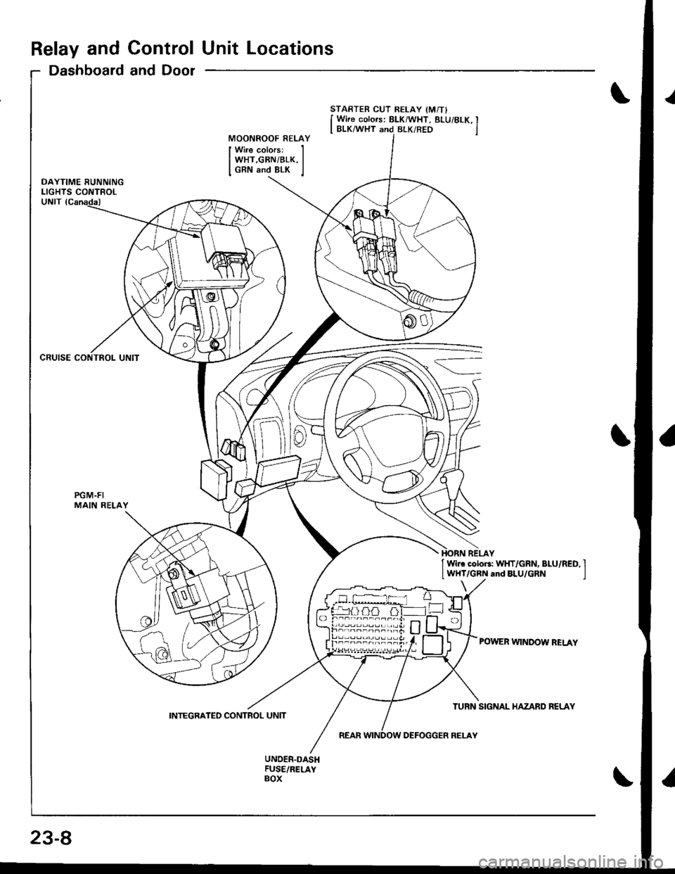
Relay and Control Unit Locations
Dashboard and Door
CRUISE CONTROL UNIT
PGM.FIMAIN RELAY
STARTER CUT RELAY IM/TI
I Wire colors: BLK/WHT, BLUi 8LK, II BLK/WHT and BLK/RED jMOONROOF RELAY
Wire colors:WHT,GBN/BLK,GRN and 8LK
I Wir. cotoF: WHT/GRN, BLU/RED, I
lWHT/GRN and BLU/GRN I
POWER WINDOW BELAY
23-8
INTEGRATED CONTROL UNIT
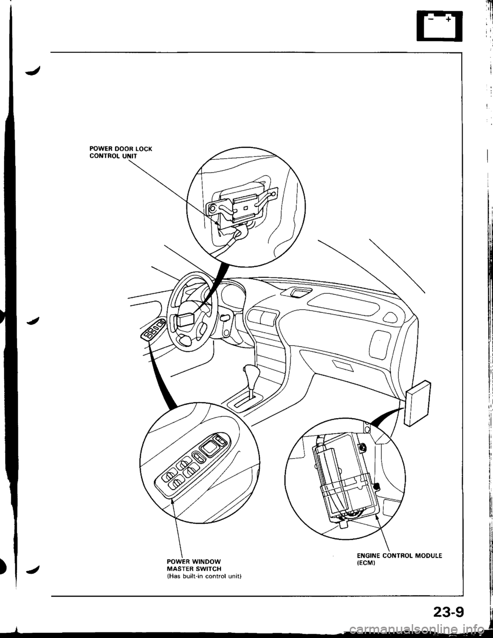
Page 1065 of 1680
POWER WINDOWMASTER SWITCHlHas built-in control unitl
Page 1066 of 1680
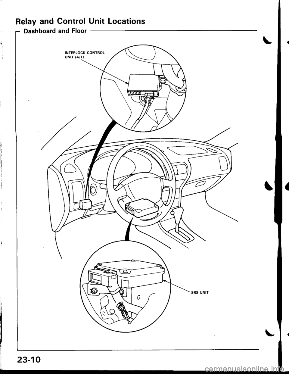
Relay and ControlUnit Locations
Dashboard and Floor
INTERLOCK CONTROLUNIT {A/T)
SS
23-10
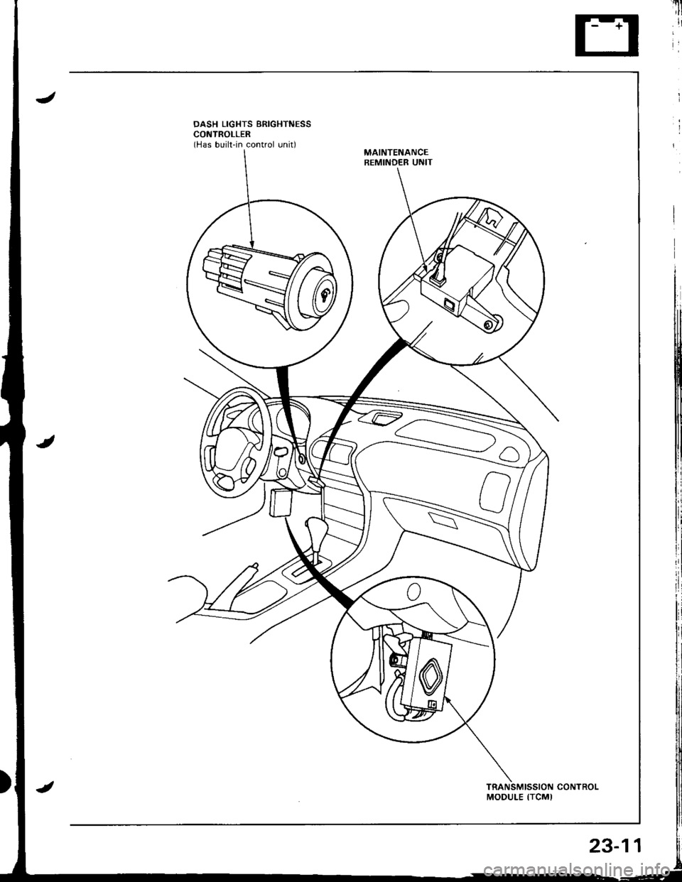
Page 1067 of 1680
'u
il'
DASH LIGHTS BRIGHTNESSCONTROLLER(Has built-in control unit)MAINTENANCEREMINDER UNIT
MODULE ITCMI
23-11
Page 1068 of 1680
Relay and Control Unit Locations
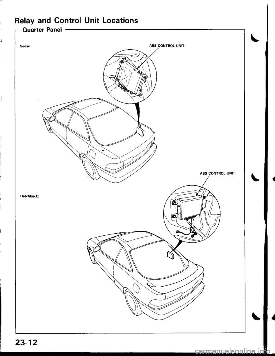
Ouarter Panel
ABS CONTROL UNIT
23-12
Page 1069 of 1680

Connector ldentification and Wire Harness Routing
JHow to ldenti{v Connectors:
ldentification numbers have been assigned to all connectors. The number is preceded by the letter "C" for connectors,"G" for single ground terminals ot "f" lor single non-ground terminals.
/
Location
HarnossEngine CompartmentDashboardOthers (Floor, Door,
Trunk. Rooll
Starter cablesT1, T2, and @
Battery ground cableG1 and O
Engine ground cable A
G2
Engine ground cable BT4
G3
Under-hood ABS fuse/relav box cableT5 and @
Engine wire harnessC101 through C134
T101 and T102
G101
A,/C wire harnessC151 through C156
G151
Engine compartment wire harnessC301 through C320
G301
Main wire harnessC201 through C223
G20'l and G202
C40l through C454
G401
Rear wire harnessC501 through C536
G501 (Sedan), G502
and G503
Dashboard wire harnessC551 through C569
G551
Driver's door wire harnessC601 through C612
Front passenger's door wire harnessC626 through C634
Left rear door wire harness (Sedan)C65l through C654
Right rear door wire harness (SedanlC656 throughc659
Roof wire harnessC661 through C667
Heater sub-harness AC671 through C677
Heater sub-harness BC68l through C684
ABS sub-harnessC701 through C706
G701 and G702
Hatch wire harness (Hatchback)C751 through C758
Spoiler sub-harness {Hatchback)C761 through C763
Rear window defogger ground wire
(Hatchback)
c11 l
G77'l
SRS main harnessC801 through C808
G801
23-13
Page 1070 of 1680

Connector ldentification and Wire Harness Routing
Starter Cables
Connectol ot
Terminal
Numbel of
CavitiesLocationConnects toNotes
Tl
r2
Right side of engine compartment
Right side oI engine compartment
Under-hood Iuse/relay box
Starter motor
oBatteryBattery positive terminal
Battely Ground Cable
Connector ol
Terminal
Numbel of
CavitiesLocationConnects toNotes
Right lront shock towerBody ground, via battery ground
caore
oBatteryBattery negative terminal
Engine Ground Cable A
Connector ol
Terminal
Number ol
CavitiesLocationConnects toNotes
T3Left side of engineValve cover
c2Left side oI engine compartmentBody ground. via engine ground
Engine Ground Cable B
Connector ol
Terminal
Numbel of
CavitiesLocationConnects toNot€s
r4Right side of engine compartmentTransmission housing
Right side of front frameBody ground, via engine ground
wire B
A/C Wire Harness
Connector or
Terminal
Number of
CavitiesLocationConnects toNotos
c 151
cl54
c156
8
2,l
Righr side of engine compartment
Left side of engine companment
Left side of engine compartment
Left side of engine compartment
Main wire harness (C207)
A,/C pressure switch
Condenser fan motor
ly'C compressor clutch
Right side of front frame
Under-hood ABS Fuse/Relav Box Cable
Connector or
Telminal
Number of
CavitiesLocationConnects toNotes
T5Right side o'f engine compartmentUnderhood ABS fuse/relay box
@Right side oI engine compaftmentBattery positive terminal
23-14
Trending: fuel type, radio, valve, 23-169, tires, charging, sub frame


