Engine ACURA INTEGRA 1998 Service Repair Manual
[x] Cancel search | Manufacturer: ACURA, Model Year: 1998, Model line: INTEGRA, Model: ACURA INTEGRA 1998Pages: 1680, PDF Size: 53.14 MB
Page 427 of 1680
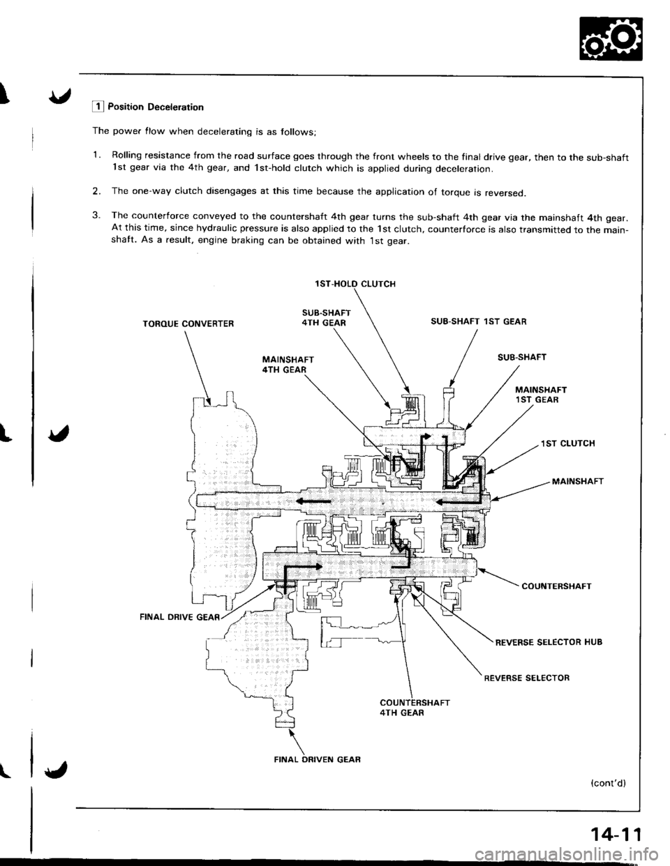
\E Position Deceleration
The power flow when decelerating is as follows;
1. Rolling resistance from the road surface goes through the front wheels to the final drive gear, then to the sub-shaft'lst gear via the 4th gear, and 1st-hold clutch which is applied during decelerarion.
2, The one-way clutch disengages at this time because the application of torque is reversed.
3. The counterforce conveyed to the countershaft 4th gear turns the sub-shaft 4th gear via the mainshaft 4th gear.At this time, since hydraulic pressure is also applied to the 1st clutch, counterforce is also transmitted to the main-shatt. As a.esult. engine braking can be obtained with 1st gear.
CLUTCH
SUB.SHAFT4TH GEARSUB-SHAFT 1ST GEAR
t
TOROUE CONVERTER
FINAL ORIVE
SUB.SHAFT
1ST CLUTCH
MAINSHAFT
COUNTERSHAFT
REVERSE SELECTOR HUB
REVERSE SELECTOR
4TH GEAR
(cont'dl
14-11
\
FINAL ORIVEN GEAR
Page 429 of 1680
I
t
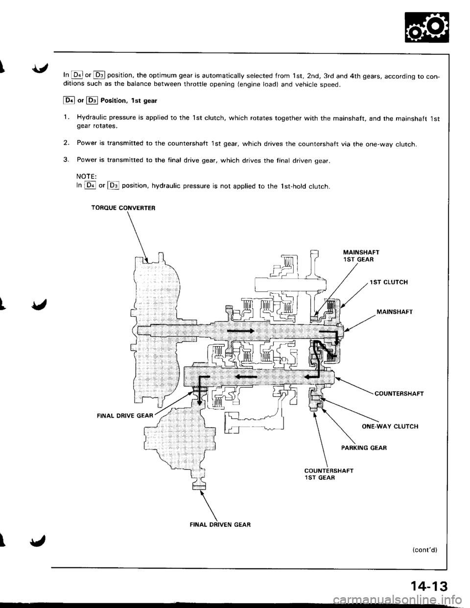
In @ or @ position, the optimum gear is automatically selected from 1st, 2nd, 3rd and 4th gears, accororng ro con-ditions such as the balance between throttle opening (engine load) and vehicle speed.
[Dn] or lDil Posirion, tsr geal
1. Hydraulic pressure is appiied to the 1st clutch, which rotates together with the mainshaft, and the mainshaft 1stgear rotates,
2. Power is transmitted to the countershaft 1st gear, which drives the countershaft via the one-way clutch.
3. Power is transmitted to the final drive gear, which drives the final driven gear.
NOTE:
In lDr'l or lDil position, hydraulic pressure is not applied to the 'tst-hold clutch.
TOROUE CONVERTER
1ST CLUTCH
MAINSHAFT
FINAL ORIVE GEAR
COUNTEBSHAFT
ONE-WAY CLUTCH
PARKING GEAR
\
14_13
,
FINAL DRIVEN GEAR
Page 436 of 1680
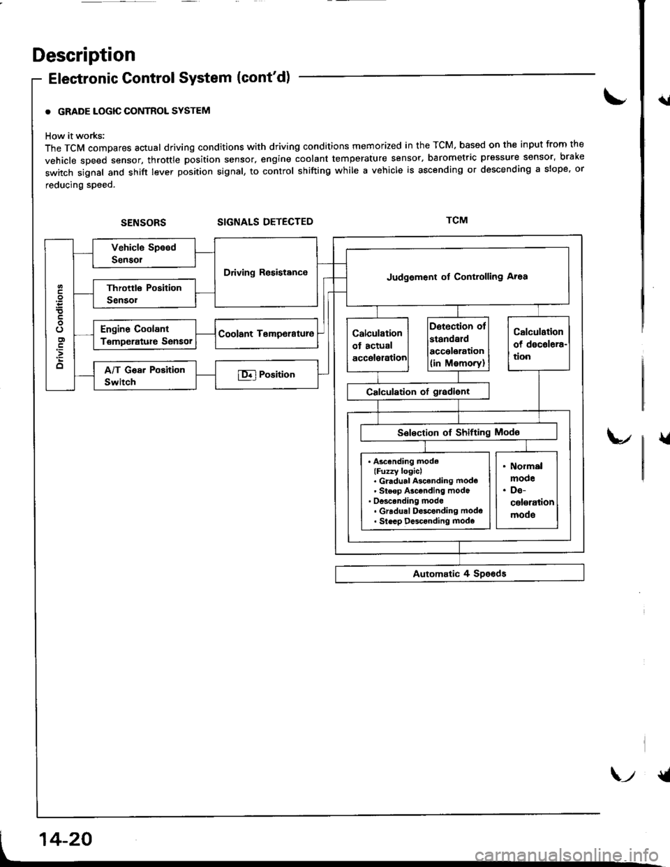
Description
Elestronic Control System (cont'd)
. GRADE LOGIC CONTROL SYSTEM
How it works:
The TCM compares actual driving conditions with driving conditions memorized in the TCM. based on th€ input from the
vehicle speed sensor, throttle position sensor, engine coolant temperature sensor, barometric pressure sensor, bral(e
switch signal and shift lever position signal, to control shifting while a vehicle is ascending or descending a slope, or
reducing speed.
SIGNALS DETECTED
{l
{
Driving ResistanceJudgement of Controlling Aroa
. Ascending mode(Fuzzy logicl. Gl.dual Ascending mode' Steop Asconding mode' oesconding mode. Gradu.l D$conding modo. Slecp D$conding modo
\-t {t
Page 437 of 1680
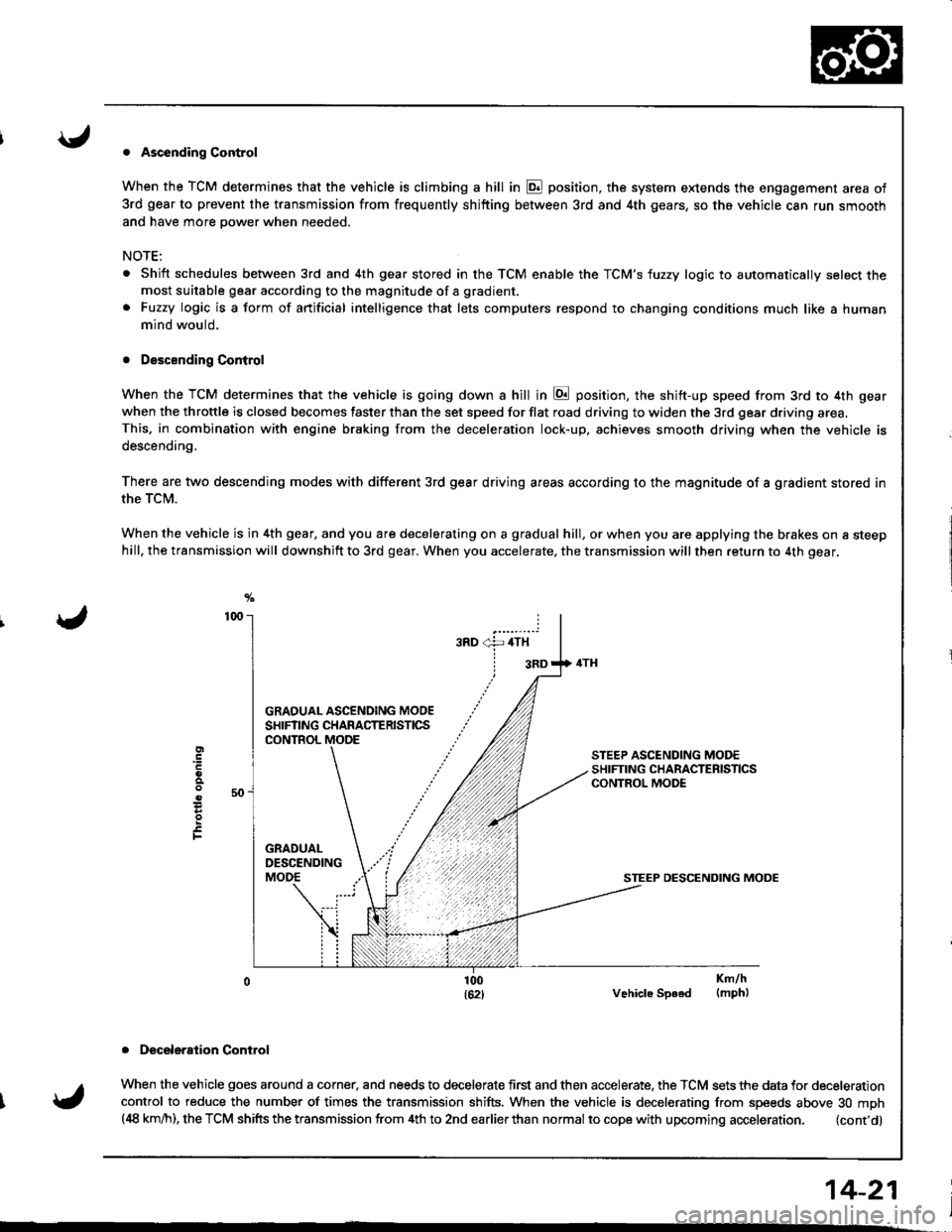
. Ascending Control
When the TCM determines that the vehicle is climbing a hill in E position, the system extends the engagement area of
3rd gear to prevent the transmission from frequently shifting between 3rd and 4th gears, so the vehicle can run smooth
and have more power when needed,
NOTE:
Shift schedules between 3rd and 4th gear stored in the TCM enable the TCM'S fuzzy logic to automatically select themost suitable gear according to the magnitude of a gradient.
Fuzzy logic is a form of artificial intelligence that lets computers respond to changing conditions much like a human
mind would,
. Descending Control
When the TCM determines that the vehicle is going down a hill in E position, the shift-up speed from 3rd to 4th gear
when the throttle is closed becomes faster than the set speed for flat road driving to widen the 3rd gear driving area.This. in combination with engine braking from the deceleration lock-up, achieves smooth driving when the vehicle is
descending,
There are two descending modes with different 3rd gear driving areas according to the magnitude of a gradient stored in
the TCM.
When the vehicle js in 4th gear, and you are decelerating on a gradual hill, or when you are applying the brakes on a steephill, the transmission will downshift to 3rd gear. When you accelerate, the transmission will then return to 4th gear,
GRAOUAL ASCENOING MOOESHIFTING CHARACTERISTICSCONTROL
STEEP DESCENDING MODE
Vehicle Speed
. Deceleraiion Control
When the vehicle goes around a corner, and needs to decelerate first and then accelerate. the TCM sets the data for deceleration
control to reduce the number of times the transmission shifts. When the vehicle is decelerating from speeds above 30 mph(,18 km/h), the TCM shifts the transmission from 4th to 2nd earlierthan normal to cope with upcoming acceleration. (cont'd)
E
F
Km/h(mph)
14-21
Page 439 of 1680
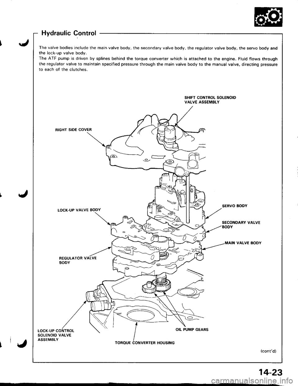
The valve bodies include the main valve body, the secondary valve body, the regulator valve body, the servo body andthe lock-up valve bodv.
The ATF pump is driven by splines behind the torque converter which is attached to the engine, Fluid {lows through
the regulator valve to maintain specified pressure through the main valve body to the manual valve, directing pressure
to each of the clutches.
SHIFT CONTROL SOLENOIDVALVE ASSEMBLY
RIGHT SIDE COVER
LOCK'UP VALVE BODYSERVO BODY
SECONDARY VALVEBODY
VALVE BODY
REGULATOR VBODY
LOCK-UPOIL PUMP GEARS
SOLENOID VALVEASSEMBLYTOROUEHOUSING
{cont'd)
%<->--::/ )C)
IrY,
14_23
'
Page 441 of 1680
I
I
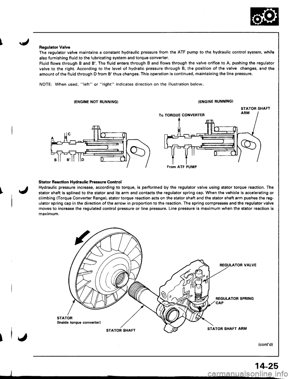
Rogulator Valve
The regulator valve maintains a constant hydraulic pressure from the ATF pump to the hydraulic control system. while
also furnishing fluid to the lubricating system and torque converter.
Fluid flows through B and B'. The fluid enters through B and flows through the valve orifice to A, pushing the regulator
valve to the right. According to the level of hydralic pressure through B. the position of the valv€ changes, and the
amount of the fluid through D from B' thus changes. This operation is continued, maintaining the line pressure.
NOTE: When used, "left" or "right" indicates direction on the illustration below.
{ENGINE NOT RUNNINGI{ENGINE RUNNINGI
STATOR SHAFT
Stator Reactior Hydrrulic Prcsrure Control
Hydraulic pressure incresse, according to torque, is performed by the regulator valve using stator torque reaction. The
stator shaft is splined to the stator and its arm end contacts the regulator spring cap. When the vehicle is accelerating or
climbing (Torque Converter Range), stator torque reaction acts on the stator shaft and the stator shaft arm pushes the reg-
ulator spring c8p in the direction of the srrow in proportion to the reaction. The spring compresses and the regulator valve
moves to incrsase the regulated conlrol pressure or line pressure. Line pressure is maximum when the stator reaction is
maximum.
TOR VALVE
{cont'dl
From ATF PUMP
I
STATOB SHAFTSTATOR SHAFT ARM
14-25
Page 445 of 1680
I
I
I
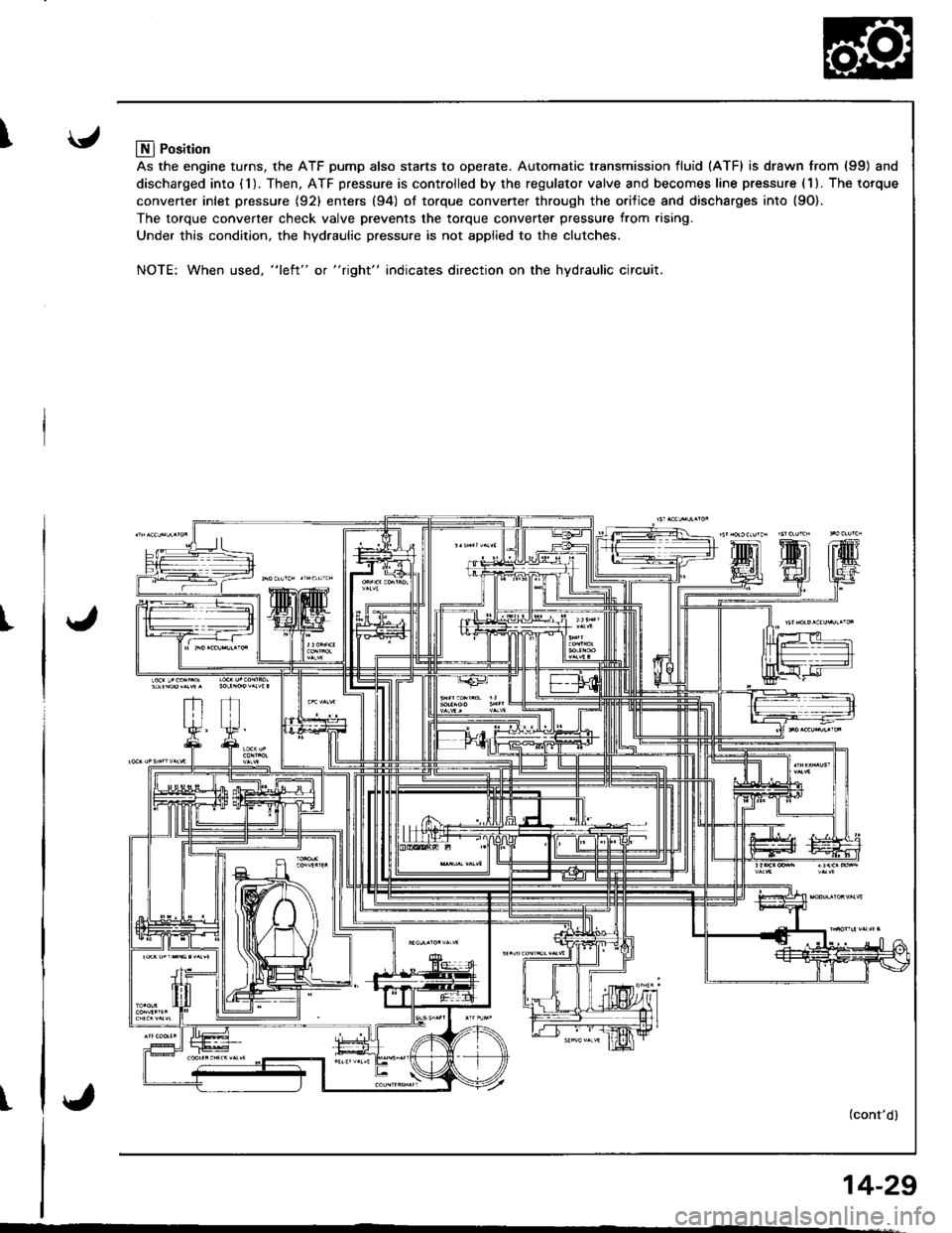
Llfl Position
As the engine turns, the ATF pump also starts to operate. Automatic transmission fluid (ATF) is drawn from (99) and
discharged into (1). Then, ATF pressure is controlled by the regulator valve and becomes line pressure (1). The torque
converter inlet pressure {92} enters (94) ol torque converter through the orilice and discharges into {9O).
The torque converter check valve prevents the torque converter pressure from rising.
Under this condition, the hydraulic pressure is not applied to the clutches.
NOTE: When used, "l€ft" or "right" indicates direction on the hydraulic circuit.
(cont'dl
14-29
Page 448 of 1680
Description
Hydraulic Flow {cont'dl
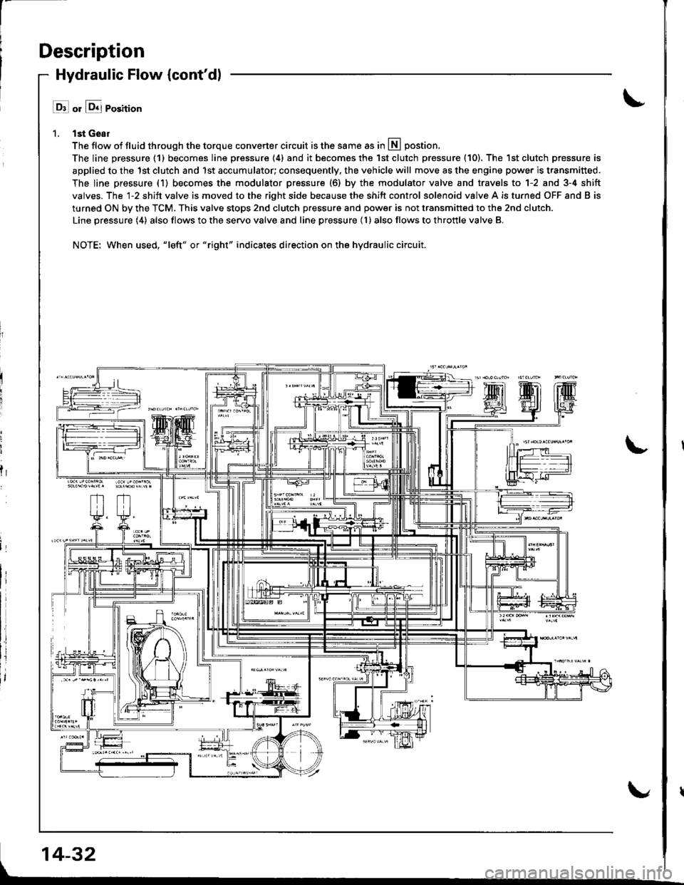
l ll or &j Position
1. lst Geal
The flow of fluid through the torque converter circuit is the same as in lll postion.
The line pressure (1) becomes line pressure (4) and it becomes the 1st clutch pressure (10). The 1st clutch pressure is
applied to the 1st clutch and 1st accumulator; consequently, the vehicle will move as the engine power is transmitted.
The line pressure (1) becomes the modulator pressure (6) by the modulator valve and travels to 1-2 and 3-4 shift
valves. The l-2 shift valve is moved to the right side because the shift control solenoid valve A is turned OFF and B is
turned ON by the TCM. This valve stops 2nd clutch pressure and power is not transmitted to the 2nd clutch.
Line pressure (4) also flows to the servo valve and line pressure (l ) also flows to throttle valve B.
NOTE: When used, "|eft" or "right" indicates direction on the hydraulic circuit.
fr
14-32
Page 454 of 1680
Description
Lock-up System
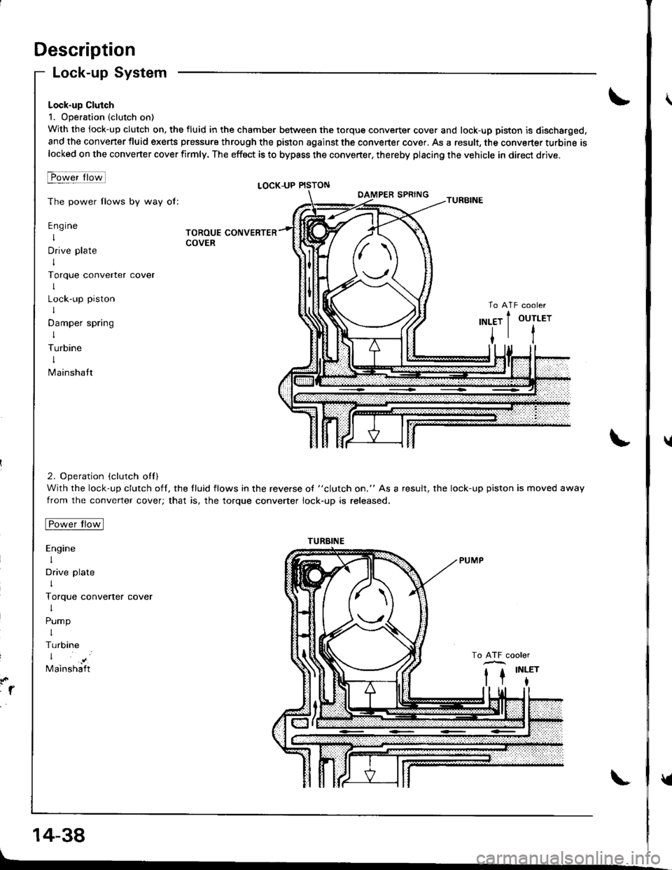
Lock-up Clutch
1. Operation (clutch on)
With the lock-up clutch on, the fluid in the chamber between the torque converter cover and lock-up piston is discharged,
and the converter fluid exerts pressure through the piston against the converter cover, As a result, the converter turbine islocked on the converter cover firmly. The effoct is to bypass the converter, thereby placing the vehicle in direct drive.
t-owerlrotl
The power flows by way of:
Engine
I
Drive plate
I
Torque converter
I
Lock-up piston
I
Damper spring
I
Turbine
I
Mainshatt
2. Operation (clutch otl)
With the lock-up clutch oft, the tluid flows in the reverse of "clutch on." As a result, the lock-up piston is moved away
from the converter cover; that is, the torque converter lock-up is released.
tro-wt rrotl
Engine
I
Drive plate
I
Torque converter cover
I
Pump
I
Turbine
Mainshaft
LOCK-UP PISTON
TOROUE CONVERTERCOVER
:1
14-38
TURBINE
tl
u
v
Page 455 of 1680
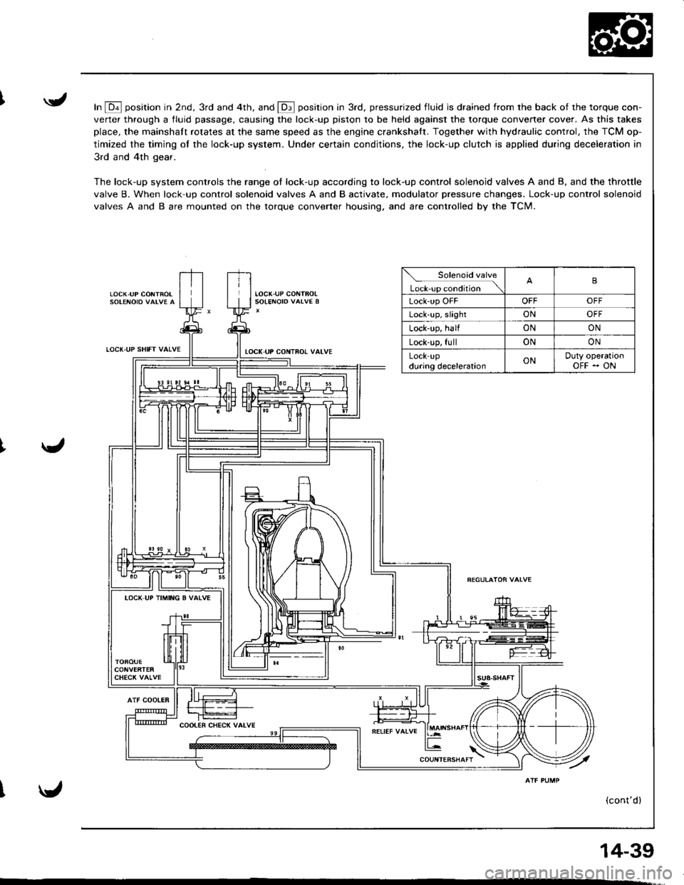
In E position in 2nd, 3rd and 4th, and E position in 3rd, pressurized fluid is drained from rhe back of the torque con-
verter through a fluid passage, causing the lock-up piston to be held against the torque converter cover. As this takes
place, the mainshaft rotates at the same speed as the engine crankshatt. Together with hydraulic control, the TCM op-
timized the timing of the lock-up system. Under certain conditions, the lock-up clutch is applied during deceleration in
3rd and 4th gear.
The lock-up system controls the range of lock-up according to lock-up control solenoid valves A and B, and the throttle
valve B. When lock-up control solenoid valves A and B activate, modulator pressure changes. Lock-up control solenoid
valves A and B are mounted on the torque converter housing. and are controlled by the TCM.
LOCK,UP CONTROL
LOCT.UP SHIfT VALVE
AlF COOIER
tocK uP coNTno! valvE
Solenoid valve
L*r""r "o.Jtio" \B
Lock'up OFFOFFOFF
Lock-up, slightONOFF
Lock-up, halfONON
Lock-up, fullONON
LOCK-Updu.ing decelerationONDuty operationOFF - ON
IOCK UP TIMING B VATVE
(cont'd)
14-39